How to Build a Mobile Grinding and Sanding Supply Cart (Fix)
I remember the first time I tried to build a mobile shop organizer. I spent three hours measuring and cutting square tubing, only to have the frame look like a trapezoid after I finished the final weld. It was a humbling moment for a guy who thought he knew how to run a bead. That project taught me that metal is a living thing; it moves, breathes, and fights you every time you pull the trigger on your welder. If you do not have a plan to manage that movement, your wheels will never sit flat on the concrete.
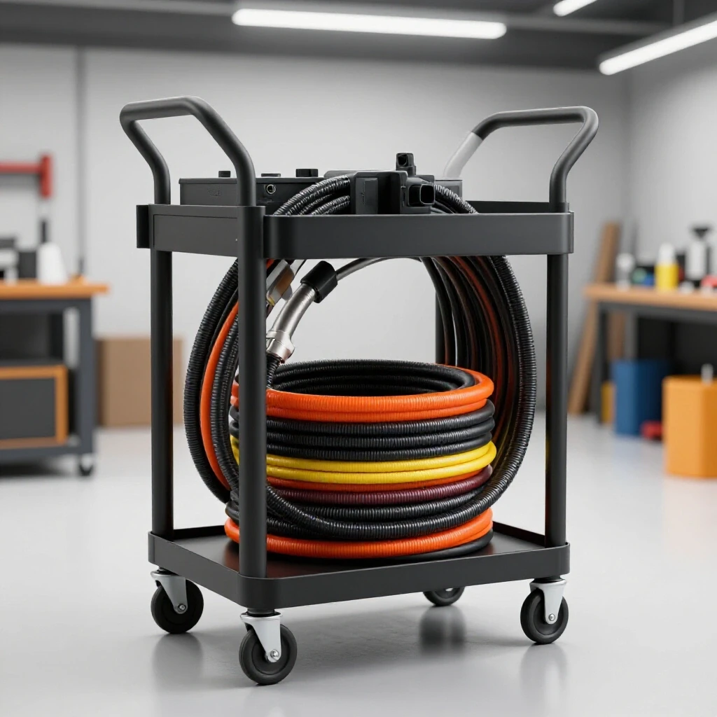
Over the last 13 years, I have built everything from utility trailers to custom chassis. The secret to a high-quality workshop organizer is not in the welding machine you use, but in the layout and the sequence of your work. We are going to walk through the process of building a heavy-duty, wheeled storage unit designed specifically to hold your grinders, sanding discs, and abrasive wheels. This build focuses on maintaining tight tolerances and controlling heat distortion so that your finished project is as straight as the day the steel left the mill.
Designing the Steel Skeleton and Calculating Kerf Allowances
Planning involves creating a cut list that accounts for the material lost during cutting (kerf) to ensure the final frame dimensions match the design specifications. Without these calculations, a frame intended to be 24 inches wide might end up 24 and 1/4 inches, throwing off your drawer fitment.
When I start a custom fabrication project, I begin with a detailed cut list. For a mobile abrasive station, I prefer using 1-inch or 1.5-inch square tubing with a 1/8-inch wall thickness. This provides enough mass to resist warping while keeping the cart light enough to roll easily. The most common mistake I see is ignoring the kerf. Kerf is the width of the material removed by the cutting blade. If you use an abrasive chop saw, you are losing about 1/8 of an inch with every cut. If you have ten cuts in a row, you could be off by over an inch by the end of the line.
To maintain a dimensional tolerance of +/- 1/16th inch, you must measure, mark, and cut on the correct side of your line. I always mark my steel with a silver streak pencil and put an “X” on the scrap side of the line. This ensures that the thickness of the blade does not eat into my finished piece.
Metal Kerf Allowances by Cutter Type
| Tool Type | Average Kerf Width | Accuracy Level |
|---|---|---|
| Abrasive Chop Saw | 0.100″ – 0.125″ | Low (High Heat) |
| Horizontal Bandsaw | 0.035″ – 0.045″ | High (Low Heat) |
| Cold Saw | 0.080″ – 0.100″ | Very High (No Heat) |
| Plasma Cutter (Manual) | 0.050″ – 0.070″ | Moderate (High Heat) |
| Angle Grinder (Thin Disc) | 0.040″ – 0.060″ | Variable |
Building on this, always verify your squareness by measuring diagonals. If the distance from the top-left corner to the bottom-right corner is exactly the same as the top-right to bottom-left, your frame is square. Even a 1/8-inch difference over a 30-inch span will cause your casters to track poorly.
Establishing a Square Foundation with Layout Fixtures
Layout fixtures are temporary or permanent structures used to hold metal components in precise alignment during the tacking process to prevent dimensional drift. These tools act as an extra set of hands that do not flinch when the heat starts to rise.
For a shop cart, you do not need a $5,000 professional welding table. You do, however, need a flat surface. If your garage floor is sloped for drainage, do not build your frame directly on the concrete. I often use a pair of heavy-duty sawhorses with two lengths of thick C-channel laid across them. I shim the C-channel until it is perfectly level in both directions. This becomes my “datum” or my reference plane.
Using workshop jigs and fixtures is about mechanical restraint. I use F-clamps and magnetic squares to lock my tubing into place before I even think about touching the welder. Interestingly, magnets can sometimes pull your arc, a phenomenon called “arc blow,” so I prefer using physical clamps whenever possible. If you are building a series of identical shelves for your sanding discs, create a simple jig by screwing scrap blocks of wood or metal to your work surface. This ensures every shelf is identical without re-measuring.
- Ensure all mill scale is ground off at the joint locations.
- Use a machinist’s square to check the verticality of upright posts.
- Space your clamps no more than 12 inches apart to prevent the tubing from bowing.
- Check your layout after every third clamp is tightened, as the pressure can sometimes shift the pieces.
Combating Metal Warping Through Strategic Tack Welding
Tack welding involves placing small, temporary welds at key points to hold a structure together before final welding, resisting the forces of thermal expansion. A tack weld should be strong enough to hold the weight but small enough to be broken or ground away if an error is discovered.
In my early days, I would tack one corner and then immediately lay a full bead. By the time I got to the third corner, the frame had pulled so far out of square that I had to cut it apart with a torch. Now, I use a “four-point tack” system. For square tubing, I place a small tack on all four sides of the joint. I keep my tacks roughly 1/4 inch in length.
The reason metal warps is due to the cooling cycle. When you weld, the steel expands. As it cools, it contracts and pulls with immense force. If you only tack one side, the cooling metal will act like a hinge, pulling the other end of the tube toward the weld. By placing tacks on opposite sides, you create a mechanical tug-of-war that keeps the part centered.
- Place the first tack on the inside of the corner.
- Check for square using a dedicated layout tool.
- Place the second tack on the outside corner to balance the pull.
- Verify the angle again; if it moved, a quick tap with a dead-blow hammer can usually reset it.
- Place the final two tacks on the remaining sides.
Mastering Weld Sequencing for Structural Integrity
Weld sequencing is the specific order in which joints are welded to balance heat input and counteract the pulling forces of cooling metal. This is the most critical stage for anyone doing custom fabrication projects who wants to avoid a twisted finished product.
I think of weld sequencing as a game of chess. You have to anticipate how the metal will react to the heat. If I weld the entire top of a cart frame in one go, the top will shrink, and the legs will splay outward like a newborn calf. To prevent this, I use a staggered sequence. I might weld the front-left corner, then move to the back-right corner. This allows the heat to dissipate and prevents any one area from becoming a “hot spot” that pulls the entire structure.
Weld Sequencing and Distortion Control Table
| Joint Type | Recommended Sequence | Distortion Risk |
|---|---|---|
| Corner Butt Joint | Weld inside, let cool, weld outside. | High (Angular pull) |
| T-Joint (Shelf Support) | Alternate sides in 1-inch increments. | Medium (Bowing) |
| Long Frame Rail | Back-step method (weld toward the start). | High (Longitudinal warp) |
| Caster Plate | Weld corners first, then centers. | Low (Plate buckling) |
The “back-step” method is a professional trick I use for long seams. Instead of welding from left to right in one long bead, I start two inches in from the right and weld back to the start. Then I move another two inches to the right and weld back to the end of the first bead. This breaks up the heat and significantly reduces the total longitudinal shrinkage.
Fabricating Custom Storage Bins and Drawer Slides
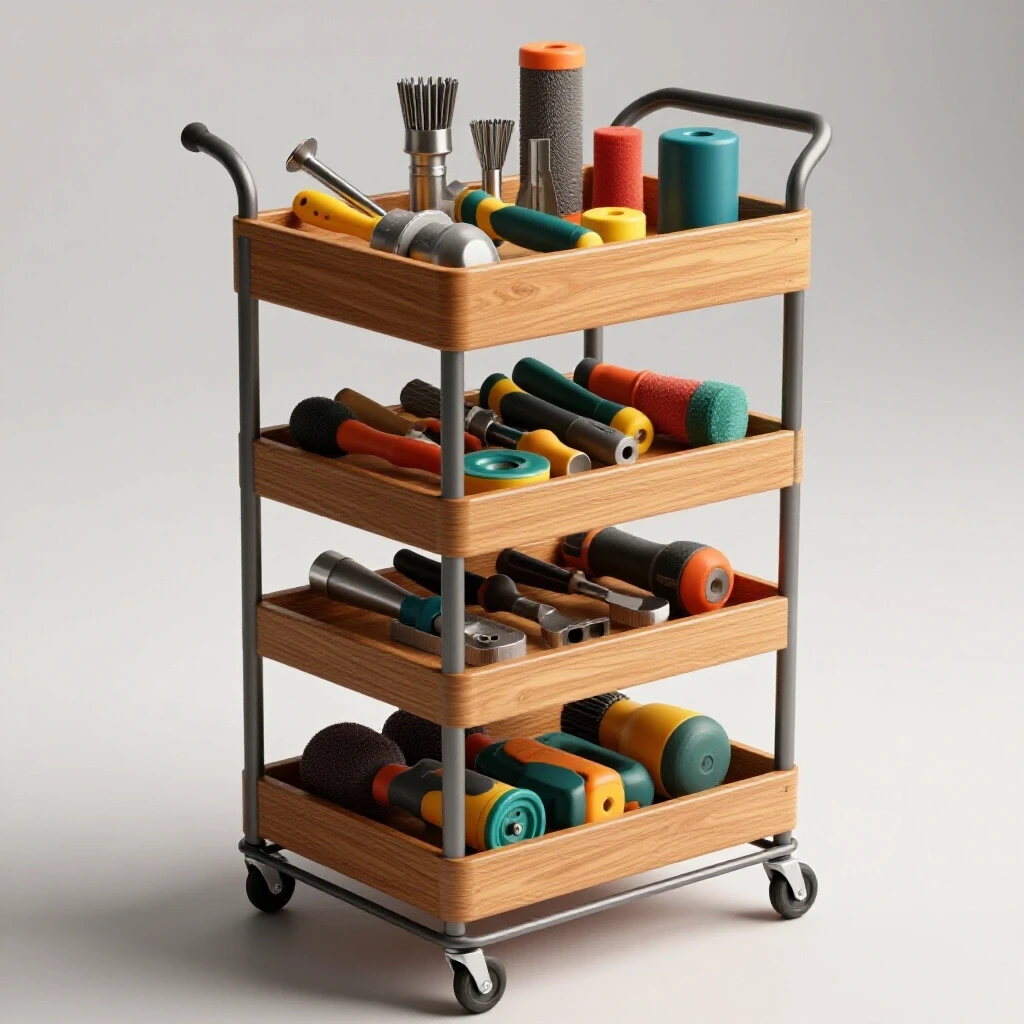
This phase involves creating internal compartments and mounting points for heavy abrasives, ensuring the center of gravity remains low for stability. A grinding supply cart needs to hold heavy items like 7-inch grinding wheels and boxes of flap discs, so the internal structure must be robust.
For the bins, I often use 16-gauge sheet metal. Cutting sheet metal accurately requires a steady hand and a good guide. I use a straight-edge clamped to the sheet and a thin 0.045-inch cutoff wheel on my grinder. When bending the lips for the bins, I use a simple “DIY brake” consisting of two pieces of heavy angle iron clamped to the edge of my workbench.
When mounting drawer slides or shelf supports, horizontal alignment is everything. I use a digital angle finder to ensure both sides are at the exact same height. If one side is even 1/16th of an inch lower, the drawer will bind or slide open on its own if the shop floor isn’t perfectly level. I prefer to weld small tabs of 1/8-inch flat bar to the frame, which then act as bolt-on points for the storage bins. This allows for future adjustments if my storage needs change.
- Keep heavy grinding wheels on the bottom shelf to lower the center of gravity.
- Use a 1/2-inch lip on all shelves to prevent items from vibrating off during transport.
- Incorporate a dedicated “holster” made from 2-inch PVC or steel pipe to hold your angle grinders by the handle.
- Ensure there is at least 2 inches of clearance between the drawers and the frame to account for weld beads.
Caster Integration and Load Distribution Principles
Mounting casters requires reinforcing the base frame to prevent the steel from buckling under the weight of tools and supplies during movement. A fully loaded cart can easily weigh 200 to 300 pounds, and all that weight rests on four small points.
I never weld casters directly to the thin-walled tubing of the frame. Instead, I weld 3/16-inch or 1/4-inch thick mounting plates to the corners of the base. These plates distribute the load over a larger surface area of the frame. When welding these plates, I use a “star pattern” similar to tightening lug nuts on a car. This prevents the plate from warping, which would make the caster sit at an angle and cause the cart to wobble.
For maximum mobility in a tight shop, I use four swivel casters. However, if you plan on pushing the cart long distances, two fixed and two swivel casters track better. I look for casters with polyurethane wheels; they are hard enough to roll over metal chips but soft enough to not crack on uneven concrete.
- Caster Plate Thickness: Minimum 3/16 inch for 1.5-inch tubing.
- Tack Count: 4 heavy tacks per plate before final welding.
- Weld Bead: 1-inch beads on each side of the plate, avoiding the very corners to prevent stress risers.
- Load Rating: Ensure each caster is rated for at least 50% of the total estimated cart weight for a safety buffer.
Correcting Heat Distortion and Final Straightening
Post-weld straightening uses mechanical force or localized heat to return a warped frame to its intended dimensions after the cooling process is complete. Even with the best sequencing, some movement is inevitable.
If I find that one corner of the cart is lifting off the floor (the “proverbial wobbly table”), I first check for a “high tack” or a bead that is protruding. If the frame itself is twisted, I use a technique called “flame straightening.” This involves heating a small spot on the side opposite the warp with an oxy-acetylene torch. As that spot cools, it shrinks and pulls the metal back into alignment. This requires a light touch; you only want the metal to reach a dull cherry red.
Another method is mechanical leverage. I have often clamped one end of a frame to my heavy welding table and used a long 2×4 or a floor jack to gently “tweak” the frame back into square. You are looking to move the metal just past its elastic limit so it takes a permanent set.
- Identify the direction of the warp using a long straight edge.
- Secure the “low” side of the frame to a fixed object.
- Apply pressure to the “high” side in small increments.
- Release and measure after every adjustment.
- Check the diagonals one last time to ensure the “fix” didn’t throw another dimension out of spec.
Lessons from the Shop Floor: A Build Log Reflection
Looking back at a recent build where I constructed a tiered organizer for my sanding belts and flap discs, I ran into a classic alignment issue. I had welded the vertical uprights but forgot to account for the angular weld shrinkage. As the welds on the inside of the joints cooled, the two uprights began to “lean” toward each other. By the time I tried to slide the top shelf in, it was 1/4 inch too wide for the opening.
I had to use a hydraulic spreader to push the uprights back out while I heated the base joints. It was a frustrating two-hour detour that could have been avoided if I had clamped a “spreader bar” (a piece of scrap cut to the exact width) between the uprights before welding. This is why I now emphasize using workshop jigs and fixtures for every step. The time it takes to build a jig is always less than the time it takes to fix a mistake.
For your project, keep a log. Note the amperage you used, the weld sequence that worked, and where the metal pulled. Over time, you develop an intuition for how a specific thickness of steel will react to your welding style. This data-driven approach is what separates a hobbyist from a fabricator.
Moving Forward with Your Fabrication Project
Building a mobile station for your abrasives is more than just a storage solution; it is a masterclass in metal control. By focusing on accurate square cuts, understanding kerf, and mastering the art of the weld sequence, you are building skills that apply to every future project, from workbenches to trailers.
The next time you stand at your saw, take the extra minute to account for the blade thickness. When you strike your arc, remember that the cooling metal is going to pull. If you anticipate that pull and counteract it with smart fixturing and sequencing, you will end up with a project that rolls smooth, sits flat, and lasts a lifetime.
- Start by sketching your frame and calculating your total linear footage of steel.
- Clean all your joint surfaces to bright metal to ensure deep penetration and clean tacks.
- Sequence your welds to move heat around the structure constantly.
- Don’t be afraid to use a hammer or a jack to make final adjustments; even the pros do it.
Frequently Asked Questions
Why does my frame always twist into a diamond shape even when I use magnets?
Magnets are great for holding pieces in place, but they do not provide enough mechanical force to resist the shrinkage of a cooling weld. As the weld pool solidifies, it pulls the metal with thousands of pounds of force. To prevent the “diamond” effect, you must use heavy-duty clamps and a four-point tacking sequence. Always measure your diagonals after tacking and again halfway through the welding process.
How much gap should I leave between pieces of tubing for a good weld?
For 1/8-inch wall tubing, a “tight fit” (zero gap) is usually best for DIY builders to maintain dimensional accuracy. However, a small 1/32-inch gap can help with full penetration if you are using a lower-powered welder. If you do leave a gap, you must be even more careful with your weld sequence, as the extra filler metal will cause more shrinkage and more warping.
What is the best way to cut square tubing so the ends are perfectly square?
A horizontal bandsaw is the most accurate tool for a home shop. If you are using an abrasive chop saw, the blade can “wander” or flex if you push too hard, resulting in an angled cut. To fix this, let the saw do the work with minimal downward pressure, and periodically check the blade-to-base angle with a machinist’s square.
My cart wobbles on three wheels. Can I fix this without cutting it apart?
Yes. First, ensure the floor is actually flat. If it is, identify the wheel that is “high.” You can often place a small shim (like a washer) between the caster and the mounting plate to level it out. If the twist is severe, you may need to use a floor jack to slightly bend the frame back into alignment, or use the flame straightening method described earlier.
Should I weld the entire outside of the frame first or the inside?
It is usually best to weld the “stiffest” part of the joint first. I prefer welding the inside corners first, as these are harder to pull. Once the insides are done and have cooled slightly, I weld the outsides. This helps balance the tension. If you weld all the outsides first, the frame will almost certainly “bow” inward.
What size tack weld is appropriate for 14-gauge or 1/8-inch tubing?
A tack should be about twice the thickness of the metal you are welding. For 1/8-inch (0.125″) tubing, a tack that is roughly 1/4 inch long is sufficient. It needs to be beefy enough to not “pop” when the metal starts to move, but small enough that you can easily grind it off if you find the part has shifted out of square.
How do I prevent the bottom shelf from warping when I weld it to the legs?
Instead of a continuous bead all the way around the shelf, use “stitch welding.” Weld 1 inch, skip 3 inches, and weld another 1 inch. This provides plenty of structural strength for a supply cart while drastically reducing the total heat input. This keeps the shelf flat and prevents the legs from pulling inward.
Why does the metal “pull” more when I use a MIG welder compared to a TIG welder?
MIG welding typically puts more heat into the surrounding metal because it is a faster process with a wider heat-affected zone (HAZ). TIG is more localized, but because it is slower, the total heat soak can sometimes be higher. In both cases, the “pull” is caused by the volume of molten metal shrinking. Using the smallest effective bead size will help minimize this.
Can I use 1-inch angle iron instead of square tubing?
You can, but angle iron is much less rigid than square tubing and is far more prone to twisting. If you use angle iron for the main frame, you will need to add more gussets and cross-braces to keep it square. For a mobile cart that carries heavy grinders, square or rectangular tubing is a much more stable choice.
How do I calculate the “true” length of a piece if I’m doing a 45-degree miter cut?
When doing miters, your “long point to long point” measurement should match the outside dimension of your frame. Remember that the kerf of the blade will take a small amount off that long point. I always cut my miters slightly “long” (by about 1/16th) and then use a disc sander to bring them to the final, exact dimension for a perfect fit.
(This article was written by one of our staff writers, Robert Kline. Visit our Meet the Team page to learn more about the author and their expertise.)