How to Design Welding Joints for Easy Torch Access (Guide)
I spent my first three years in a heavy equipment repair shop thinking that if I could see a joint, I could weld it. That assumption cost me a week of rework and nearly a thousand dollars in wasted structural steel when a loader bucket frame I’d fabricated failed during its first lift. The issue wasn’t my machine settings or the rod I chose; it was the fact that I had designed a corner where the torch nozzle physically couldn’t maintain the correct angle. I had created a “blind spot” in the metal, leading to a shallow weld that looked fine on the surface but lacked any real penetration at the root.
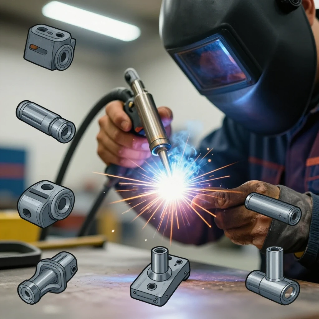
In my 14 years as a mechanical engineer and fabricator, I have learned that structural safety begins long before you strike an arc. It starts at the drawing board—or the workbench—when you decide how two pieces of metal will meet. If you cannot get your torch into the joint at a consistent 15 to 45-degree angle, you are essentially gambling with the structural integrity of your project. This guide focuses on the intersection of joint geometry and physical access to ensure your builds are safe, stable, and repeatable.
The Physics of Structural Integrity and Joint Accessibility
Structural integrity is the ability of a welded assembly to hold its rated weight without breaking or deforming. Joint accessibility is the physical room required for the welder to position the torch and filler metal correctly to achieve full fusion between the base metals.
When we talk about structural metal load capacity, we are looking at how force travels through a joint. If a weld is “cold” or shallow because the torch was held at an awkward, steep angle, the load path is interrupted. This creates a stress riser, a point where tension concentrates and eventually leads to a crack. In my experience, most garage fabrication safety issues stem from these internal defects that are hidden from the naked eye.
Understanding the Heat-Affected Zone (HAZ)
The Heat-Affected Zone, or HAZ, is the area of base metal that hasn’t melted but has had its microstructure changed by the intense heat of the welding process. This area is often the weakest point of a structural weld because the heat can make the metal more brittle.
If you design a joint with poor access, you often end up “dwelling” in one spot too long as you struggle to get the metal to flow into a tight corner. This excessive heat input expands the HAZ, significantly reducing the tensile strength of the surrounding steel. I always tell my students: a quick, clean pass in a well-designed joint is always stronger than a labored, over-heated weld in a cramped space.
Managing Shielding Gas Flow and Porosity
Welding gas flow rate is a critical metric for preventing porosity, which is the presence of tiny gas bubbles trapped inside the weld metal. For most manual MIG or TIG operations in a workshop, a flow rate of 15–20 CFH (cubic feet per hour) is standard.
However, if your joint design is too deep or narrow, the shielding gas can become turbulent or fail to reach the bottom of the joint. This lack of coverage allows oxygen and nitrogen from the air to contaminate the molten puddle. When I inspect failed frames, I often find “Swiss cheese” metal inside the joint—a direct result of designing a pocket where gas couldn’t settle properly.
Standard Joint Geometries and Path Clearance
Joint geometry refers to the specific shape and cross-section of the area where two metal parts are joined. Path clearance is the unobstructed volume of space surrounding that joint, allowing for the natural movement of the torch and the fabricator’s hand.
Designing for access means respecting the physical dimensions of your equipment. A standard MIG gun nozzle is roughly 1/2 to 5/8 of an inch in diameter. If you place two stiffeners only an inch apart, you leave no room for the 15-degree tilt needed for proper shielding and puddle control. I recommend maintaining a minimum clearance of 1.5 to 2 inches around any critical structural joint to allow for hand-eye coordination and torch maneuverability.
Tackling the Shadow Effect in T-Joints
The shadow effect occurs when a vertical component of a joint physically blocks the torch from reaching the root at the necessary angle. This is particularly common in T-joints where a gusset or brace is placed too close to a corner.
To avoid this, I use a simple rule of thumb: the height of the vertical member should not interfere with a 45-degree bisecting angle of the torch. If the torch hits the metal before the wire reaches the root, the joint must be redesigned. You might need to move the brace or use a different joint type, such as a lap joint, to open up the workspace.
Optimizing Butt Joints for Full Penetration
A butt joint consists of two pieces of metal laid end-to-end in the same plane. While they seem simple, they require a specific gap—often 1/16 to 1/8 of an inch for 1/4-inch plate—to allow the heat to reach the bottom.
Without this root gap, the torch merely melts the top surface, leaving the bottom of the plates unjoined. In structural applications, I always bevel the edges of plates thicker than 3/16 of an inch. A 60-degree included angle (30 degrees on each plate) creates a “V” that guides the torch and ensures the weld bead is as thick as the parent metal itself.
| Joint Type | Recommended Torch Angle | Minimum Clearance | Common Failure Point |
|---|---|---|---|
| Butt Joint | 90° (Vertical) to 15° (Travel) | 1″ above plate | Lack of root penetration |
| T-Joint (Fillet) | 45° (Work) to 15° (Travel) | 2″ side-to-side | “Shadowing” the root |
| Lap Joint | 30° to 60° (Work) | 1.5″ side-to-side | Undercutting the top edge |
| Corner Joint | 45° (Work) | 2″ exterior | Burn-through on thin edges |
Workshop Safety and PPE Integration in Design
Workshop safety protocols involve the use of personal protective equipment (PPE) and environmental controls to prevent injury. Design for access must account for the fact that a welder is wearing a bulky helmet and thick gloves, which further limits the space available.
When I plan a project, I don’t just look at the metal; I look at where my head will be. If a joint is tucked inside a narrow box, my welding helmet might hit the workpiece, forcing me to look at the arc from a distorted angle. This leads to poor weld placement and potential safety close-calls, like bumping into hot metal or losing balance.
Selecting the Right PPE Shade
For most workshop fabrication involving 1/8-inch to 1/2-inch steel, a Shade 10-13 filter is necessary to protect your eyes from flash burn. Modern auto-darkening helmets are fantastic, but they require a clear line of sight to the arc to trigger the sensors.
If your joint design is so cramped that the helmet’s sensors are “shaded” by the workpiece, the lens might flicker or fail to darken. This is a major safety hazard. Designing open joints ensures that your helmet sensors can see the arc, keeping your vision protected throughout the duration of the weld.
Ventilation and Gas Management
Garage fabrication safety relies heavily on proper airflow. When welding in tight, enclosed corners, welding fumes can accumulate quickly, displacing breathable air. I always use a workshop safety checklist that includes a dedicated fume extractor or a high-volume fan positioned to pull smoke away from my face.
If a joint is designed as a deep “pocket,” it can trap shielding gas, which is often heavier than air (like Argon). In a small shop, this can lead to localized oxygen depletion. By keeping joints open and accessible, you allow for better natural ventilation and easier access for fume extraction nozzles.
Structural Load-Testing and Diagnostic Inspection
Structural load-testing is the process of applying force to a completed weldment to verify it can handle its intended stress. Diagnostic inspection involves using visual or physical tools to find internal weld defects before the project is put into service.
I’ve found that the joints that are the hardest to reach are also the hardest to inspect. If I can’t get a flashlight and a magnifying glass into a corner to check for cracks or undercut, I don’t trust the weld. For risk-averse fabricators, the ability to inspect the work is just as important as the ability to perform it.
Identifying Internal Weld Defects
A welding defect troubleshooting routine should always include a search for “undercut” and “overlap.” Undercut is a groove melted into the base metal next to the weld toe that isn’t filled by the weld metal. Overlap is when the weld metal rolls over the surface of the base metal without fusing.
Both of these issues are common when torch access is restricted. When you’re fighting for space, you tend to move the torch inconsistently. I use a “weld gauge” to measure the leg length and throat thickness of my fillet welds. If the design doesn’t allow room for the gauge to fit, the design is flawed and needs adjustment for better verification.
Calculating Structural Safety Margins
In professional engineering, we use safety factors to account for uncertainty. For a non-critical shop table, a 2:1 safety factor might be enough (the table is twice as strong as it needs to be). For something structural like a car rotisserie or an overhead hoist, I aim for a 4:1 or even 5:1 margin.
These margins are quickly eaten up by poor joint design. A weld with only 50% penetration—caused by poor torch access—effectively cuts your safety factor in half. I always assume my manual welds will have some minor imperfections, so I design my joints to be easily accessible to maximize the odds of getting a “perfect” 100% penetration weld.
Step-by-Step Joint Verification Checklist
Before you cut any metal, run your design through this verification process. I use this five-point audit for every structural project I undertake in my shop.
- Torch Mock-up: Take your (unplugged) welding gun or torch and physically place it in the joint. Can you maintain a 15-45 degree angle throughout the entire length of the weld?
- Visual Path: Put on your welding helmet. Can you see the “root” of the joint clearly from a comfortable sitting or standing position?
- Glove Clearance: Ensure there is at least 1 inch of space between your gloved hand and any adjacent metal surfaces to prevent burns and allow for smooth movement.
- Gas Pocket Check: Identify if the joint creates a “cup” shape that might trap gas or cause turbulence. If so, can you tilt the workpiece to allow gas to flow out?
- Inspection Access: Is there enough room to fit a wire brush and a flashlight into the area after welding to clean and inspect the bead?
Real-World Case Study: The Suspension Link Failure
A few years ago, I consulted on a project where a hobbyist was building a custom off-road suspension. He had designed a “double-shear” bracket that was incredibly strong on paper. However, the two plates of the bracket were spaced so closely together that he couldn’t get his MIG nozzle between them to weld the inner seams.
He decided to only weld the outside of the plates, thinking the thickness of the metal would compensate. During a low-speed test, the bracket “unzipped.” The lack of internal fusion meant the entire load was placed on the outer skin of the weld, which exceeded the metal’s shear stress threshold. We redesigned the bracket to be a two-piece assembly that allowed full access to all four sides of the mounting plates. The second version has survived three years of heavy use without a single crack.
Advanced Tools for Structural Verification
While old-school experience is vital, modern technology offers great support for the risk-averse builder. I’ve started using a few digital and chemical tools that make a huge difference in my shop.
- Electronic Gas Flow Regulators: These provide a much more accurate reading than traditional “floating ball” flowmeters, ensuring my 17 CFH is actually 17 CFH.
- Dye Penetrant Inspection Kits: This is a three-part chemical spray (cleaner, penetrant, developer) that pulls bright red dye into even the smallest surface cracks. It’s an affordable way to perform NDT (non-destructive testing) in a home garage.
- Digital Angle Finders: I use these to ensure my bevels are exactly 30 degrees, which guarantees that my torch has the “opening” it needs to reach the root.
- Borescope Cameras: For joints inside tubing or tight enclosures, a cheap USB borescope allows me to see the back-side of a weld to verify penetration.
Conclusion: Designing for Success
Building structural metal projects is a rewarding challenge, but it demands a respect for the physical limits of both the material and the tools. By prioritizing torch access during the design phase, you eliminate the root cause of many common fabrication failures. You ensure that your shielding gas protects the puddle, your heat stays within the intended zone, and your welds achieve the full penetration required for safety.
Remember that a complex design is not necessarily a better design. Often, the most robust structures are those with simple, open joints that allow the fabricator to do their best work. My next step for you is to take a hard look at your current project. Pick the most difficult joint and perform the “Torch Mock-up” I described earlier. If it feels tight or awkward, don’t try to “power through” it. Stop, redesign, and give yourself the room to build something that will last a lifetime.
Frequently Asked Questions
Why is torch angle so important for structural strength?
The torch angle determines how deeply the heat penetrates the metal and how the shielding gas covers the molten pool. If the angle is too steep (too close to the metal), you risk pushing the gas away and creating a shallow, weak weld. If it’s too flat, the wire might skip over the root, leading to a lack of fusion.
What is the minimum gap I should leave for a structural butt weld?
For 1/4-inch thick steel, a gap of 3/32 to 1/8 of an inch is standard. This allows the arc to reach the bottom edges of the plates. For thinner materials like 1/8-inch, a 1/16-inch gap or a slight bevel is usually sufficient.
How does poor access lead to “undercut” in a weld?
When you can’t reach a joint easily, you often have to use a longer “stick-out” (the distance between the nozzle and the metal). This makes the arc less stable. To compensate, builders often slow down, which puts too much heat on the top edge of the joint, melting it away without adding enough filler metal to replace it.
Can I use a smaller nozzle to get into tight spaces?
Yes, you can use “tapered” or “bottleneck” nozzles for MIG welding, or a “stubby” gas lens for TIG. However, these smaller nozzles provide less gas coverage. If you use them, you must be extremely careful with your gas flow rates and travel speed to avoid porosity.
What is the “root” of a weld, and why does it matter?
The root is the point where the two pieces of base metal are closest together at the bottom of the joint. In a structural weld, the root must be completely melted and fused. If the root remains cold, it acts like a pre-existing crack that will eventually grow under stress.
How do I know if my joint design is “shadowing” my weld?
If you place your torch in the joint and any part of the nozzle or your hand hits the surrounding metal before you can point the wire directly at the corner, you are shadowing the root. You should be able to “see” the very bottom of the V or corner clearly through your helmet.
What are the signs of poor gas coverage in a deep joint?
The most obvious sign is “porosity,” which looks like tiny holes or bubbles on the surface of the weld. You might also see a heavy brown or grey soot around the weld, or the arc might make a “popping” or “hissing” sound instead of a steady hum.
Is it better to “push” or “pull” the torch in tight corners?
In MIG welding, “pushing” (pointing the torch in the direction of travel) generally provides better visibility and gas coverage in tight spots. “Pulling” (dragging the torch) provides deeper penetration but makes it harder to see where you are going in a cramped joint. For most structural shop work, a slight push angle is preferred for better puddle control.
(This article was written by one of our staff writers, James Harlan. Visit our Meet the Team page to learn more about the author and their expertise.)