How to Drill Consistent Repeat Hole Patterns in Steel (Tips)
I have spent 14 years navigating the realities of the shop floor, often moving between the precision of mechanical engineering and the grit of heavy metal fabrication. My career has been defined by a deep respect for the physical forces that govern steel. Early in my journey, I watched a structural frame fail during a load test because a series of holes were just three-sixteenths of an inch out of alignment. That error did not just waste material; it created a stress riser that led to a catastrophic crack in the heat-affected zone of a nearby joint.
In my experience, the most dangerous moments in a workshop do not always involve sparks or heavy machinery. They often occur during the quiet phase of layout and preparation. When you are working on a project in your garage, the stakes are high. A misaligned bolt hole might seem like a minor annoyance, but in a load-bearing structure, it represents a failure of the load path. I write this guide to help you bridge the gap between “close enough” and the structural verification required for safe, repeatable results.
The Physics of Material Stress and Hole Placement
Structural integrity relies on how force moves through a piece of metal, a concept known as the load path. When we remove material by drilling, we create a disruption in the internal grain of the steel, which can lead to stress concentrations if the holes are not placed with precision.
Tensile strength is the maximum amount of pulling stress a material can withstand before failing. In a workshop setting, we often work with A36 mild steel, which has a yield strength of about 36,000 PSI. When you drill a series of apertures, you are effectively reducing the cross-sectional area of the steel. If your spacing is inconsistent, one section of the metal may be forced to carry more weight than another, leading to a brittle fracture or structural deformation.
Understanding Shear Stress and Yield Points
Shear stress occurs when forces act parallel to a cross-section of the material, such as a bolt trying to “slice” through a hole. If your holes are not perfectly aligned across two mating surfaces, the bolt will not sit flush. This creates a point-load rather than a distributed load.
- Yield Strength: The point where metal deforms permanently (36,000 PSI for A36).
- Ultimate Tensile Strength: The point where the metal actually breaks (58,000 to 80,000 PSI).
- Safety Factor: I always recommend a 4:1 safety factor for overhead or structural builds, meaning the design should handle four times the expected load.
How Hole Arrays Affect Structural Load Paths
When you create a pattern of holes, you must consider the “net section” of the steel. This is the remaining material after the holes are removed. If holes are too close together, the steel between them can “zip” open under tension. Industry standards usually suggest a minimum distance of three times the bolt diameter between hole centers to maintain the structural metal load capacity.
Essential Layout Tools for Positional Accuracy
Achieving identical spacing across multiple workpieces starts with a disciplined layout process rather than relying on the drill bit to find its way. I have seen many fabricators lose hours of work because they used a dull pencil or a thick marker for their initial marks.
A transfer punch is a hardened steel tool used to “transfer” the exact center of an existing hole onto a new piece of metal. This is the gold standard for ensuring two plates will bolt together. By using a punch that matches the diameter of the existing hole, you eliminate the parallax error that comes from trying to eyeball the center.
Scribing and Center Punching Techniques
Using a carbide-tipped scribe is far more accurate than using a pen. A scribe creates a physical groove in the surface of the steel that your center punch can “lock” into. I always use a two-step punching process: a light tap with a prick punch for location, followed by a heavy strike with a center punch to create a pilot seat for the drill bit.
- Scribe: Used for fine, hair-width lines that do not rub off.
- Prick Punch: A 30-degree point tool for high-accuracy marking.
- Center Punch: A 60-degree or 90-degree point tool that creates a large enough divot to prevent drill bit “walk.”
Utilizing Edge Guides and Precision Squares
To keep your holes in a straight line relative to the edge of the steel, an edge guide or a combination square is vital. I prefer using a heavy-duty machinist’s square to ensure my vertical layout lines are perfectly perpendicular to the base. If your layout is off by even one degree, a three-foot-long piece of steel will show a significant deviation at the far end.
Creating Shop-Made Jigs for Identical Spacing
When you need to replicate the same pattern across five, ten, or twenty pieces of steel, manual layout becomes a liability. Human error increases with fatigue. This is where a simple, low-tech jig becomes the most valuable tool in your workshop.
A jig is a custom-made guide that holds the workpiece in a fixed position and directs the tool. For drilling, a “drill bush” or a hardened steel template is the best way to ensure every piece is a carbon copy of the first. I often make my templates out of a scrap piece of the same material I am drilling to ensure the thickness and behavior are consistent.
Building a Hardened Steel Template
I recommend creating a “master” piece first. Take your time to measure, scribe, and drill this master piece with extreme care. Once verified, you can clamp this master directly onto your subsequent workpieces. To prevent the drill bit from enlarging the holes in your master template over time, you can press-fit hardened steel bushings into the guide holes.
- Select a piece of flat bar as your master template.
- Layout the hole pattern using a height gauge or precision calipers.
- Drill the holes on a drill press to ensure they are perfectly vertical.
- Deburr the holes to ensure the template sits flush against the next workpiece.
Implementing Stop Blocks and Edge Fences
If you are using a drill press, you can achieve repeatability without a full template by using stop blocks. A stop block is simply a piece of wood or steel clamped to the drill press table that limits how far the workpiece can slide. By setting a fence (a long straight edge) and a stop block, you create a physical “pocket” that positions the steel in the exact same spot every time.
| Layout Method | Accuracy Level | Speed for 10+ Pieces | Risk of Error |
|---|---|---|---|
| Manual Tape Measure | Low (+/- 1/16″) | Very Slow | High |
| Scribe & Calipers | Medium (+/- 0.010″) | Slow | Moderate |
| Master Template | High (+/- 0.005″) | Fast | Low |
| Stop Blocks on Press | High (+/- 0.005″) | Very Fast | Very Low |
Drill Press Operations and Safety Protocols
The drill press is a powerful tool, but it is also one of the most common sources of workshop injuries. I have seen workpieces “helicopter” when a drill bit catches, leading to broken fingers and deep lacerations. Workshop safety is not just about wearing the right gear; it is about the physics of how you secure your work.
Always clamp your work. Never rely on your hand strength to hold a piece of steel while drilling, especially as the bit exits the bottom of the hole. This is the moment when the torque is highest and the bit is most likely to grab the metal and spin it.
Managing Heat and Friction in Steel
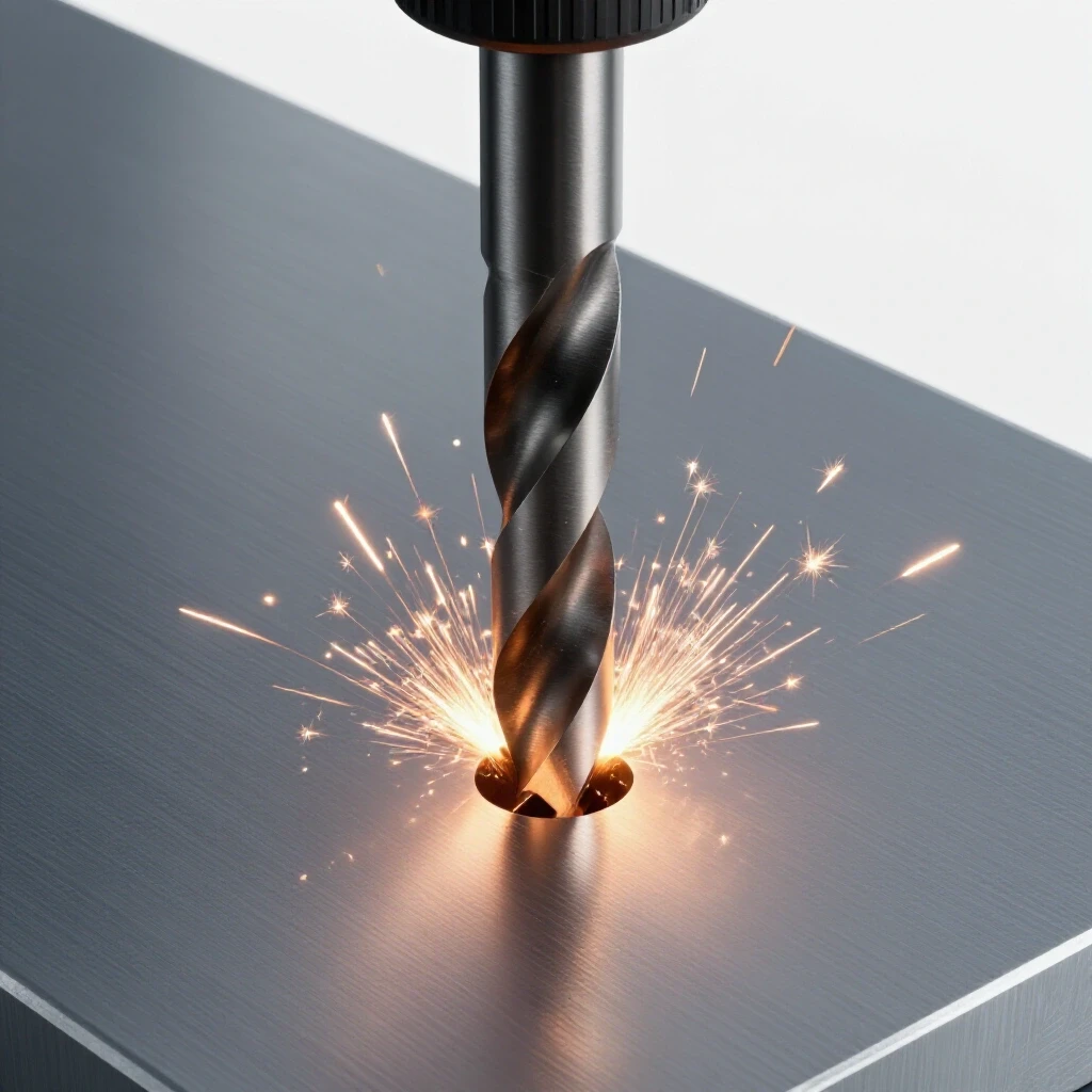
Drilling steel generates immense heat. This heat can lead to a phenomenon called work-hardening, where the steel becomes harder than the drill bit itself. Once a hole work-hardens, you will likely ruin your bit trying to finish it. To prevent this, you must use cutting fluid and maintain the correct “feed and speed.”
- RPM (Revolutions Per Minute): Larger bits need to spin slower.
- Feed Pressure: You need enough pressure to keep the bit “biting” and creating a continuous chip.
- Coolant: Use a dedicated cutting oil to carry heat away from the cutting edge.
PPE and Workshop Safety Checklist
Before you pull the lever on the drill press, you should go through a mental safety audit. I have seen near-misses where loose clothing or long hair was nearly caught in the spindle.
- Eye Protection: Wear Z87+ rated safety glasses. A face shield is recommended for heavy drilling where large hot chips are ejected.
- No Gloves: This is counterintuitive to some, but never wear gloves while operating a drill press. A glove can get caught in the rotating bit and pull your hand into the machine.
- Secure the Table: Ensure the drill press table is locked tight and will not pivot under the pressure of the drill.
- Clear the Swarf: Use a brush, never your hands, to remove the metal curls (swarf) from the work area.
Analyzing Structural Failures from Drilling Errors
In my years of industrial inspection, I have analyzed numerous joint failures that started with a poorly drilled hole. One specific case involved a heavy equipment trailer. The fabricator had “forced” a bolt through two misaligned holes by using a hammer. This created a pre-existing stress in the bolt and the surrounding plate.
When the trailer hit a bump, the dynamic load exceeded the remaining capacity of the stressed bolt. The bolt sheared, and the sudden transfer of energy caused a brittle fracture in the steel plate. This could have been avoided if the holes had been drilled using a proper transfer punch or a jig to ensure a “slip-fit” alignment.
Identifying Brittle Fracture and Fatigue Points
A brittle fracture is a sudden break that occurs without much prior deformation. It often starts at a sharp corner or a nick in a hole. If your drill bit is dull, it can create a “torn” surface inside the hole rather than a smooth one. These tiny tears act as “stress risers” where cracks can begin to grow over time due to vibration or repeated loading.
- Symptom: Fine cracks radiating from the edge of a bolt hole.
- Cause: Poorly finished holes or excessive vibration.
- Prevention: Always deburr the edges of your holes with a countersink bit or a file to remove sharp edges.
Material Performance and Yield Strength Data
When selecting your steel, keep in mind that the thickness of the material changes how it reacts to being drilled. Thinner sheets (under 1/8 inch) are prone to “triangular” holes if not backed by a piece of wood or scrap steel. Thicker plates (over 1/2 inch) require pilot holes to reduce the force needed on the final drill size.
| Steel Thickness | Pilot Hole Required? | Recommended RPM (1/2″ Bit) | Cooling Method |
|---|---|---|---|
| 1/8″ (11 Gauge) | No | 600 – 800 | Light Oil Mist |
| 1/4″ | Optional | 400 – 600 | Constant Oil Drip |
| 1/2″ | Yes (1/8″ Pilot) | 250 – 350 | Heavy Cutting Fluid |
| 1″ | Yes (1/4″ Pilot) | 150 – 200 | Flood Coolant / Deep Lube |
Advanced Techniques for Positional Repeatability
If you are working on a project that requires extreme precision, such as a custom engine mount or a precision tool stand, you might need to move beyond basic stop blocks. One technique I use is “stack drilling.”
Stack drilling involves clamping multiple pieces of steel together and drilling through all of them at once. This ensures that the hole pattern is identical across every piece in the stack. However, this requires a very sturdy drill press and long, high-quality drill bits. You must ensure the stack is perfectly square to the spindle, or the holes will “drift” as they go deeper.
Using Step Bits for Thin Gauge Steel
For sheet metal and thin-walled tubing, a standard twist drill often grabs and tears the metal. I prefer using a step bit (often called a Unibit). The stepped design allows the bit to shave the metal away gradually, which prevents the “grabbing” effect and results in a much rounder, cleaner hole.
The Importance of Deburring for Flush Fitment
A hole is not finished until it is deburred. When a drill bit exits the steel, it leaves a “burr”—a sharp ridge of displaced metal. If you do not remove this burr, your mating parts will not sit flush against each other. This creates a gap that can allow the joint to flex, leading to bolt fatigue and eventual failure. Use a large drill bit or a dedicated 90-degree countersink tool to lightly chamfer the edge of every hole.
Final Inspection and Verification Framework
Before you move to the assembly phase, you must verify your work. I follow a simple structural verification checklist for every project I build. This ensures that I haven’t missed a subtle error that could compromise the build.
- Visual Alignment Check: Lay your mating parts on top of each other. Can you see daylight clearly through every hole in the pattern?
- Bolting Test: Can you thread the bolts through by hand? If you need a hammer, your holes are misaligned.
- Measurement Audit: Use a set of calipers to check the distance from the edge of the metal to the center of the first and last holes.
- Surface Flatness: Ensure that the drilling process hasn’t warped the plate (common in thin materials).
By treating every hole as a critical structural element, you elevate your work from hobbyist-level to industrial-grade. The frustration of a wasted afternoon and ruined steel is a high price to pay for rushing the layout phase. Take the time to build a jig, sharpen your bits, and respect the physics of the material.
Frequently Asked Questions
Why does my drill bit keep “walking” away from my mark? Drill bits “walk” because they are designed to cut, not to find a center. If the tip of the bit doesn’t have a deep enough physical divot to sit in, it will follow the path of least resistance across the surface of the steel. Always use a center punch to create a substantial starting point. For larger holes, start with a small pilot bit (about 1/8 inch) before moving to your final size.
How can I ensure holes stay aligned when drilling through thick square tubing? Drilling through both sides of a tube in one pass often leads to misalignment because the bit can flex or “wander” inside the hollow space. I recommend drilling the first side, then flipping the tube and using a square or a transfer punch to mark the second side. Alternatively, use a drill press with a perfectly squared table and a short, rigid bit to minimize deflection.
What is the best way to drill a long row of holes at 2-inch intervals? The best way is to use a “pinning jig.” Drill your first hole, then move the piece 2 inches and drop a pin (or a bolt) through your first hole into a corresponding hole in your jig or drill press fence. This “locks” the spacing for the next hole. This method prevents “incremental error,” where being off by 1/32 of an inch on each hole adds up to a massive error by the end of the row.
Is it safe to use a handheld drill for repeat patterns in 1/4-inch steel? While possible, it is difficult to maintain the vertical alignment (perpendicularity) required for structural joints. If you must use a handheld drill, use a “drill guide” attachment or a small block of wood with a pre-drilled vertical hole to act as a guide. Always wear eye protection and be prepared for the drill to kick back if the bit catches.
What should I do if I misdrill a hole by a small amount? Do not “wallow out” the hole with the side of the drill bit. This creates an oval shape that weakens the structural joint and prevents the bolt from seating properly. If the error is small, you may be able to use a reamer to slightly enlarge the hole properly. If the error is large, it is often safer to scrap the piece or weld the hole shut and redrill, though welding changes the material properties and should be done with caution.
How do I know what speed to set my drill press to? The general rule is: the harder the material and the larger the bit, the slower the speed. For a 1/2-inch bit in mild steel, 300-400 RPM is a good starting point. If you see blue chips, you are generating too much heat and need to slow down or use more lubricant. If the bit is “chattering” or vibrating loudly, you may need to increase the pressure or decrease the speed.
Can I use a standard wood drill bit for steel? No. Wood bits (like spade bits or brad-point bits) are made of different steel and have a geometry that will immediately dull or shatter when hitting metal. Only use High-Speed Steel (HSS), Cobalt, or Carbide-tipped bits designed specifically for metalworking. Cobalt bits are particularly good for stainless steel or harder alloys.
How do I prevent the “burr” on the back side of the hole? A burr is inevitable, but you can minimize it by slowing down your feed pressure just as the bit starts to break through the bottom. Placing a “sacrificial” piece of scrap steel tightly underneath your workpiece (backing) will also support the metal and significantly reduce the size of the exit burr.
(This article was written by one of our staff writers, James Harlan. Visit our Meet the Team page to learn more about the author and their expertise.)