How to Secure Workpieces Safely on a Drill Press (Guide)
I have spent the last 14 years in metal fabrication shops, transitioning from a floor hand to a mechanical engineer and structural inspector. During that time, I have seen exactly what happens when a rotating cutting tool meets a piece of metal that is not properly restrained. It is rarely a quiet event. Usually, it involves a loud bang, a shattered bit, and a workpiece transformed into a dangerous, spinning propeller. My goal is to share the hard-won lessons from those near-misses and structural failures so you can approach your workshop projects with a data-driven mindset and a healthy respect for physical forces.
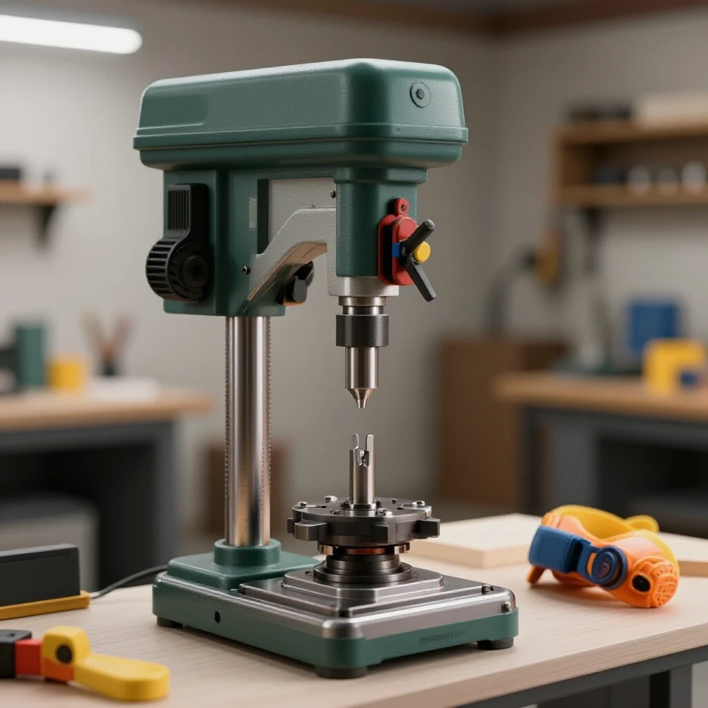
Understanding Rotational Torque and Axial Lift Forces
Mechanical forces in a workshop are often invisible until they exceed the holding capacity of your setup. In a drilling operation, the motor generates rotational torque to turn the bit, while the feed handle applies axial force to push it through the material. If the friction between the bit and the metal becomes greater than the friction holding your workpiece in place, the part will rotate at the same speed as the spindle.
Rotational torque is the twisting force produced by the machine’s motor, measured in foot-pounds or Newton-meters. Axial lift occurs most frequently as the drill bit exits the bottom of a hole, where the “web” of the bit catches the remaining thin flake of metal and attempts to pull the entire workpiece up the flutes. Understanding these two vectors of force is the foundation of structural metal load capacity and overall shop safety.
The Physics of the “Propeller Effect”
The propeller effect occurs when a workpiece breaks free from its restraints and spins rapidly with the drill spindle. This usually happens because the operator relied on hand strength rather than mechanical fixturing, or because the clamping force was insufficient to overcome the torque of a large-diameter bit.
In my early years, I watched a colleague try to hold a small 1/4-inch steel plate by hand while drilling a 1/2-inch hole. As the bit broke through the back, it grabbed the material. The plate spun, slicing through his leather glove and deep into his palm. This was a classic failure to respect torque. When a bit catches, the motor’s energy is transferred instantly into the workpiece. If you are not using a workshop safety checklist that mandates mechanical clamping, you are essentially gambling with your physical safety.
Essential Mechanical Fixturing for Workpiece Stability
Properly restraining a part requires mechanical advantages that exceed the maximum torque the machine can produce. This is achieved through various tools like vises, strap clamps, and T-slot bolts that anchor the material directly to the machine table. A secure setup ensures that the hole is placed accurately and that the material does not deform under pressure.
Securing a part is not just about preventing it from spinning; it is about creating a rigid bridge between the tool and the machine. This rigidity prevents vibration, which is a leading cause of premature tool wear and poor surface finish. By using industry-standard fixturing, you ensure that the forces are directed into the heavy cast-iron table of the machine rather than into your joints or the air.
Utilizing the Machine Vise as a Primary Restraint
A machine vise is a precision-machined tool designed to grip workpieces between two flat, parallel jaws. It is the most common method for securing parts because it provides high clamping pressure and a stable base. However, a vise is only effective if it is bolted to the table using T-bolts and nuts.
I have inspected many failed structural joints where the root cause was an unbolted vise. When the vise is not secured to the table, it can still spin if the bit catches. I recommend using a safety factor of at least 2:1 when considering clamping force. For structural steel like A36, which has a yield strength of approximately 36,000 PSI, the vise must hold the part firmly enough that it cannot shift, but not so tightly that it causes permanent deformation or “crushing” of the material.
Implementing Strap Clamps and Step Blocks
Strap clamps are adjustable metal bars used in conjunction with step blocks to pin a workpiece directly to the machine table. This method is ideal for large or irregularly shaped parts that cannot fit inside a standard vise. The step blocks act as a fulcrum, allowing the clamp to apply downward pressure.
When using strap clamps, the bolt should be positioned closer to the workpiece than to the step block. This creates a mechanical advantage that maximizes the downward force on the part. If the bolt is too far away, the clamp may flex, leading to a loss of stability. In structural fabrication, ensuring that your part is level and flat against the table is critical for maintaining the intended load path of the final assembly.
| Fixturing Method | Primary Force Resisted | Best Use Case | Risk Level if Misused |
|---|---|---|---|
| Bolted Machine Vise | Rotational & Lateral | Small to medium blocks | Moderate |
| Strap Clamps & Step Blocks | Axial Lift & Rotational | Large plates or odd shapes | Low |
| V-Blocks | Lateral (Rolling) | Cylindrical or round stock | High |
| T-Slot Stop Blocks | Rotational | Preventing “spin” on long parts | Moderate |
Managing Material Stress and Structural Integrity
Every time you drill into a piece of metal, you are altering its structural properties. The heat generated by the friction of the bit can create a small heat affected zone (HAZ) around the hole. While this is less dramatic than the HAZ found in welding, it can still lead to localized hardening or brittleness in high-carbon steels.
Understanding the structural metal load capacity of your material is essential. If you are drilling holes for a load-bearing frame, the placement and quality of those holes determine the overall strength of the structure. A hole that is “walked” or ovalized due to poor clamping creates a stress riser. This is a point where tension concentrates, potentially leading to structural cracking or brittle fracture under load.
Preventing Heat-Related Material Weakness
Excessive heat during drilling can degrade the mechanical properties of certain alloys. While we aren’t dealing with the 15-20 CFH gas flow rates used in MIG welding, the thermal energy is still significant. If a workpiece is not secured tightly, it may vibrate, increasing friction and heat.
In my experience inspecting heavy equipment frames, I’ve seen cases where “chatter” during the drilling process caused micro-fractures in the material. These fractures are similar to welding defect troubleshooting issues like cold-lapping. To prevent this, ensure your setup is rigid. A rigid setup allows the bit to cut cleanly, carrying the heat away in the chips rather than soaking it into the workpiece.
Calculating Safety Margins for Structural Builds
When designing a project that will hold weight—like a shop gantry or a vehicle bracket—you must account for safety margins. A safety factor of 4:1 is common in critical structural applications. This means the joint is designed to hold four times the expected maximum load.
Securing your workpiece correctly ensures the hole is perfectly perpendicular. If a hole is drilled at an angle because the part shifted, the bolt passing through it will be subjected to shear stress rather than simple tension. This reduces the effective strength of the fastener and the joint. Always verify your setup with a square and a dial indicator if precision is paramount to the structural integrity of the build.
Workshop Safety Protocols and Environmental Control
A safe workshop is a controlled environment where risks are identified and mitigated before a machine is ever turned on. This involves everything from your personal protective equipment (PPE) to the layout of your floor space. Garage fabrication safety starts with a clean, organized area where you aren’t tripping over cords while handling heavy metal.
Safety is not just about the moment of operation; it is about the preparation. This includes checking that your lighting is adequate to see your layout marks and ensuring that your PPE is rated for the task at hand. While you don’t need a Shade 10-13 filter for drilling as you would for arc welding, high-impact eye protection is mandatory to guard against high-velocity metal chips.
PPE Integration and Eye Protection
Eye injuries are the most common accidents in metalworking shops. When drilling, the bit produces “swarf”—long, sharp curls of metal—and smaller chips that can fly several feet. Standard prescription glasses are not enough; you need Z87+ rated safety glasses that provide side protection.
In addition to eye protection, consider the risks of gloves. While I mentioned a colleague whose hand was saved from a deeper cut by a glove, gloves are actually a major hazard around rotating machinery. If a glove finger catches on a rotating bit, it can pull your entire hand into the machine before you can react. My rule in the shop is: no gloves, no loose clothing, and no jewelry when operating the drill press.
Creating a Secure Shop Layout
Your workshop safety checklist should include an audit of your machine’s physical location. The drill press should be bolted to the floor or a heavy workbench to prevent it from tipping. There should be enough clearance around the machine so that long pieces of material do not strike other tools or people if they happen to rotate.
- Clearance Zone: Maintain at least 3 feet of clear space around the spindle.
- Lighting: Use a dedicated task light to eliminate shadows on the workpiece.
- Floor Condition: Ensure the floor is free of oil and metal chips to prevent slips.
- Emergency Stop: Verify the “off” switch is easily accessible and not blocked by the vise or clamping setup.
Diagnostic Inspection and Quality Control
Once a hole is drilled, the job isn’t finished. You must inspect the work to ensure it meets the structural requirements of your project. This involves checking for burrs, measuring the hole diameter, and verifying the location against your blueprints.
In industrial settings, we use non-destructive testing (NDT) to find hidden flaws. While you may not need an ultrasonic tester in a home shop, a simple visual inspection with a magnifying glass can reveal a lot. Look for “tearing” inside the hole or discoloration that indicates excessive heat. These are signs that your clamping was insufficient or your feed rate was incorrect.
Identifying Internal Defects and Surface Marring
If a workpiece moves during the operation, it often leaves “witness marks”—scratches or gouges where the clamps or vise jaws slipped. In structural metalwork, these marks are more than just cosmetic issues. They can act as starting points for fatigue cracks, especially in parts subjected to vibration.
If you find that your part moved, you must evaluate whether the piece is still structurally sound. If the hole is oversized or out of alignment, the load path will be compromised. In my 14 years of fabrication, I have scrapped many parts because a 1/16-inch shift in the drill press led to a failure in the final assembly. It is always cheaper to restart with a new piece of steel than to risk a structural failure later.
A Practical Workshop Safety Checklist for Securing Parts
Before you pull the lever on the drill press, go through this mental or physical checklist to ensure your setup is safe and structurally sound.
- Is the vise or fixture bolted to the table? Never rely on the weight of the vise alone.
- Is the workpiece supported underneath? Use parallels or a sacrificial “spoiler board” to prevent the metal from bending under axial pressure.
- Is there a “stop” to prevent rotation? If possible, position the workpiece or the vise so it rests against the left side of the machine column.
- Are all loose items removed? Clear away wrenches, chuck keys, and debris.
- Is the material thickness appropriate for the bit size? Ensure the clamping pressure won’t collapse thin-walled tubing.
Case Study: The Failure of an Unsecured Support Bracket
I once investigated a failure involving a custom-made support bracket for a hydraulic press. The fabricator had drilled a series of 1-inch holes in 1/2-inch plate steel. Because the plate was heavy, he assumed it wouldn’t move and only used a single C-clamp to hold it to the table.
During the drilling of the third hole, the bit caught as it exited the material. The torque was so great that it snapped the C-clamp. The plate spun, striking the drill press column and bending the spindle. More importantly, the hole was elongated and the surrounding metal was stressed. When the bracket was later put into service, it failed at that specific hole under a load of only 5,000 PSI—well below its calculated limit. The movement during drilling had created a microscopic fracture that grew into a full-scale structural failure.
Conclusion and Next Steps
Securing your work is the difference between a successful fabrication and a dangerous workshop accident. By applying the principles of mechanical fixturing and respecting the physics of torque and axial lift, you can produce parts that are both accurate and structurally sound. Remember that every hole you drill is a functional part of a larger system; treat it with the same precision you would a critical weld.
Your next step is to audit your current clamping tools. If you don’t have a set of T-bolts and a dedicated machine vise, make those your next priority. Start practicing with scrap material, testing how much force it takes to move a part under different clamping configurations. This hands-on experience, combined with a rigorous safety mindset, will turn you into a more confident and capable fabricator.
Frequently Asked Questions
Why shouldn’t I hold a workpiece by hand if I’m using a small drill bit?
Even small bits can generate significant torque if they bind in the material. A 1/8-inch bit can easily spin a small piece of sheet metal, which acts like a razor blade. Furthermore, hand-holding lacks the rigidity needed for an accurate hole, often leading to bit breakage and flying debris.
What is the purpose of using parallels inside a vise?
Parallels are precision-ground metal bars used to raise the workpiece above the bottom of the vise while keeping it perfectly level. This allows you to drill through the material without damaging the vise itself. They ensure that the axial force of the drill is distributed evenly across a flat surface.
How do I prevent thin sheet metal from “grabbing” and lifting up the bit?
Thin material is highly prone to axial lift. To secure it safely, sandwich the sheet metal between two pieces of sacrificial plywood or thicker scrap metal. Clamp this “sandwich” tightly to the table. This supports the metal at the exit point, preventing the bit from catching the edges.
Can I use a C-clamp to secure a vise to the drill press table?
While a C-clamp is better than nothing, it is not a recommended industrial practice. C-clamps can vibrate loose or slip off the rounded edges of a cast-iron table. Dedicated T-bolts that fit into the table’s slots provide a much more secure and positive mechanical connection.
What should I do if the workpiece starts to spin?
If a part breaks free and starts spinning, do not attempt to grab it or stop it. Step back immediately and hit the emergency stop button or pull the power plug if it is safe to reach. Wait for the spindle to come to a complete stop before assessing the damage.
How does clamping affect the heat affected zone (HAZ)?
While clamping doesn’t change the temperature of the bit, a secure, rigid setup prevents vibration. Vibration creates extra friction, which generates more heat. By keeping the part perfectly still, you allow the drill’s flutes to eject chips efficiently, which is the primary way heat is removed from the hole.
Is there a specific safety factor I should use for my clamps?
In general shop work, a 2:1 safety factor for clamping force is standard. This means your clamps should exert twice the downward force that the drill bit exerts in upward axial lift. For critical structural components, increasing this to 4:1 ensures that no shifting occurs, preserving the material’s integrity.
Why is the “breakthrough” point of drilling the most dangerous?
As the bit reaches the bottom of the material, the thickness of the metal decreases until it can no longer resist the downward force. At this moment, the bit often stops cutting and starts “grabbing” the remaining thin web of metal. This sudden increase in torque is when most workpieces break free.
What are “witness marks” and why do they matter?
Witness marks are indentations or scratches left on the metal by clamping tools. While often ignored in hobby work, in professional fabrication they indicate that the material shifted or that the clamping pressure was high enough to deform the surface. These marks can become stress concentrators that lead to future structural failure.
Do I need to worry about welding gas flow rates when drilling?
No, welding gas flow (measured in CFH) is specific to shielding the weld pool from oxygen. However, the mindset of environmental control is the same. Just as you monitor gas flow for a clean weld, you must monitor your clamping setup for a clean, safe, and structurally sound hole.
(This article was written by one of our staff writers, James Harlan. Visit our Meet the Team page to learn more about the author and their expertise.)