How to Mark Steel Accurately with Carbide Scribes (Guide)
I have spent the last 14 years in the trenches of mechanical engineering and shop floor fabrication, often acting as the final line of defense against structural failure. In my career, I have seen massive industrial frames buckle and precision-machined components discarded as scrap, all because of a single misplaced line during the initial layout phase. For many intermediate fabricators, the transition from hobbyist projects to structurally sound builds is fraught with anxiety over material distortion and joint failure. This fear is healthy; it respects the physical forces of gravity and tension that don’t care about our good intentions.
When I first started inspecting industrial steel components, I noticed a recurring theme: errors in the final assembly almost always traced back to the first five minutes of the project. If your initial markers are off by even a fraction of a millimeter, that error compounds as you cut, grind, and weld. By the time you reach the final assembly, a 1-millimeter error at the base can translate into a 10-millimeter gap at the top of a structural column. Achieving precision layout on steel is not just about aesthetics; it is a fundamental safety protocol that ensures load paths are correctly aligned and weld joints are properly fitted.
Understanding Steel Surface Integrity and Layout Precision
Precision layout on steel involves using hardened tools to create fine, permanent reference points on a workpiece. This process allows a fabricator to translate complex engineering drawings into physical reality with high dimensional accuracy. By creating a physical indentation in the metal, you ensure that your reference marks will not smudge or burn away during the high-heat phases of fabrication.
In the world of structural verification, we talk a lot about “fit-up.” According to the American Welding Society (AWS) D1.1, the gap between two joining members significantly impacts the strength of the finished weld. If your layout is inaccurate, your fit-up will be poor, forcing you to “bridge” gaps with excess weld metal. This often leads to internal defects like lack of fusion or excessive porosity, which can cause a joint to fail under load.
When I prepare a piece of A36 mild steel for a critical frame, I treat the surface preparation as a prerequisite for safety. A clean surface allows the carbide tip to bite into the metal rather than skating over mill scale or oils. Mill scale is a flaky, oxidized layer that forms during the hot-rolling process of steel production. If you scribe directly onto mill scale, your line might literally flake off halfway through the project, leaving you guessing where your cut line was.
Comparison: Scribe Performance on Different Steel Grades
| Steel Grade | Hardness (Brinell) | Scribe Interaction | Risk Factor |
|---|---|---|---|
| A36 Mild Steel | 120-160 | Excellent “bite”; clear lines | Low; easy to control |
| 4140 Chromoly | 197-240 | Requires more pressure | Moderate; tip wear increases |
| AR400 (Wear Plate) | 360-440 | Surface is very resistant | High; scribe may skate |
| Stainless 304 | 123-201 | Work hardens quickly | Low; prone to scratching |
The Mechanics of Carbide Tip Geometry and Material Hardness
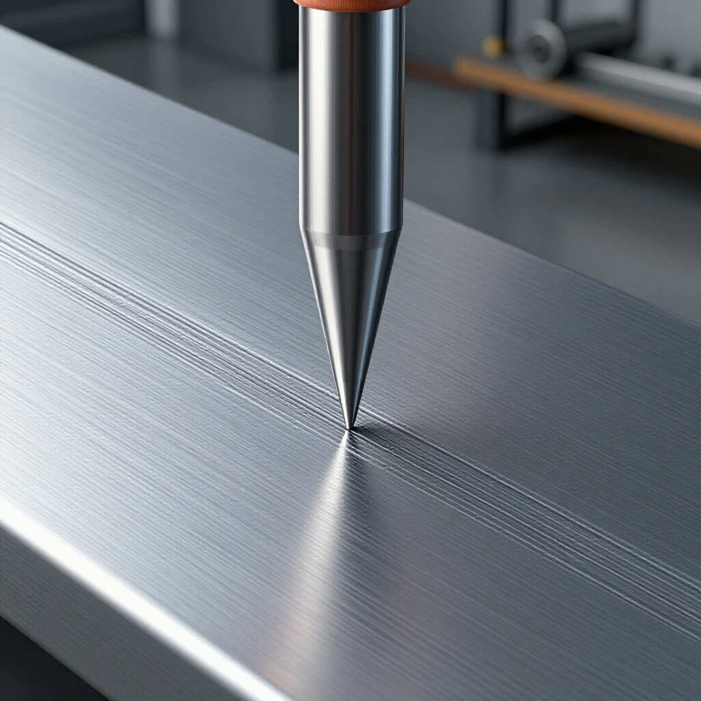
The effectiveness of a layout tool depends on the relationship between the hardness of the marking tip and the hardness of the steel being marked. Carbide-tipped tools utilize tungsten carbide, a compound that is significantly harder than standard carbon steel. This hardness allows the tool to displace metal and create a permanent groove without the tip dulling rapidly.
Tungsten carbide sits at approximately 9 on the Mohs scale, while mild steel sits between 5 and 6. This disparity is why a carbide tip can “plow” through the surface of the steel. However, the geometry of that tip—usually ground to a 60-degree or 90-degree included angle—is what determines the precision of your line. A sharp, narrow angle allows the scribe to sit closer to your straightedge, reducing the “offset” error that occurs when the line is drawn slightly away from the intended measurement.
I recall a project involving a heavy-duty engine hoist where the fabricator used a dull, rounded marking tool. Because the tool couldn’t create a crisp line, the holes for the main pivot pin were misaligned by nearly 3 millimeters. When the hoist was loaded to its 2-ton capacity, the pin experienced uneven shear stress because it wasn’t sitting square in the holes. The resulting “clipping” of the pin could have led to a catastrophic drop. Using a sharp carbide tip ensures that your center-punch marks for drilling are exactly where they need to be, maintaining the structural load path.
Key Metrics for Layout Precision
- Tip Angle: 60 degrees for general layout; 90 degrees for heavy etching.
- Offset Distance: Typically 0.1mm to 0.3mm depending on tool thickness.
- Line Width: Aim for a consistent 0.15mm width for high-accuracy work.
- Hardness Ratio: Tool should be at least 2x harder than the workpiece.
Managing Stress Risers and Structural Fatigue in Etched Steel
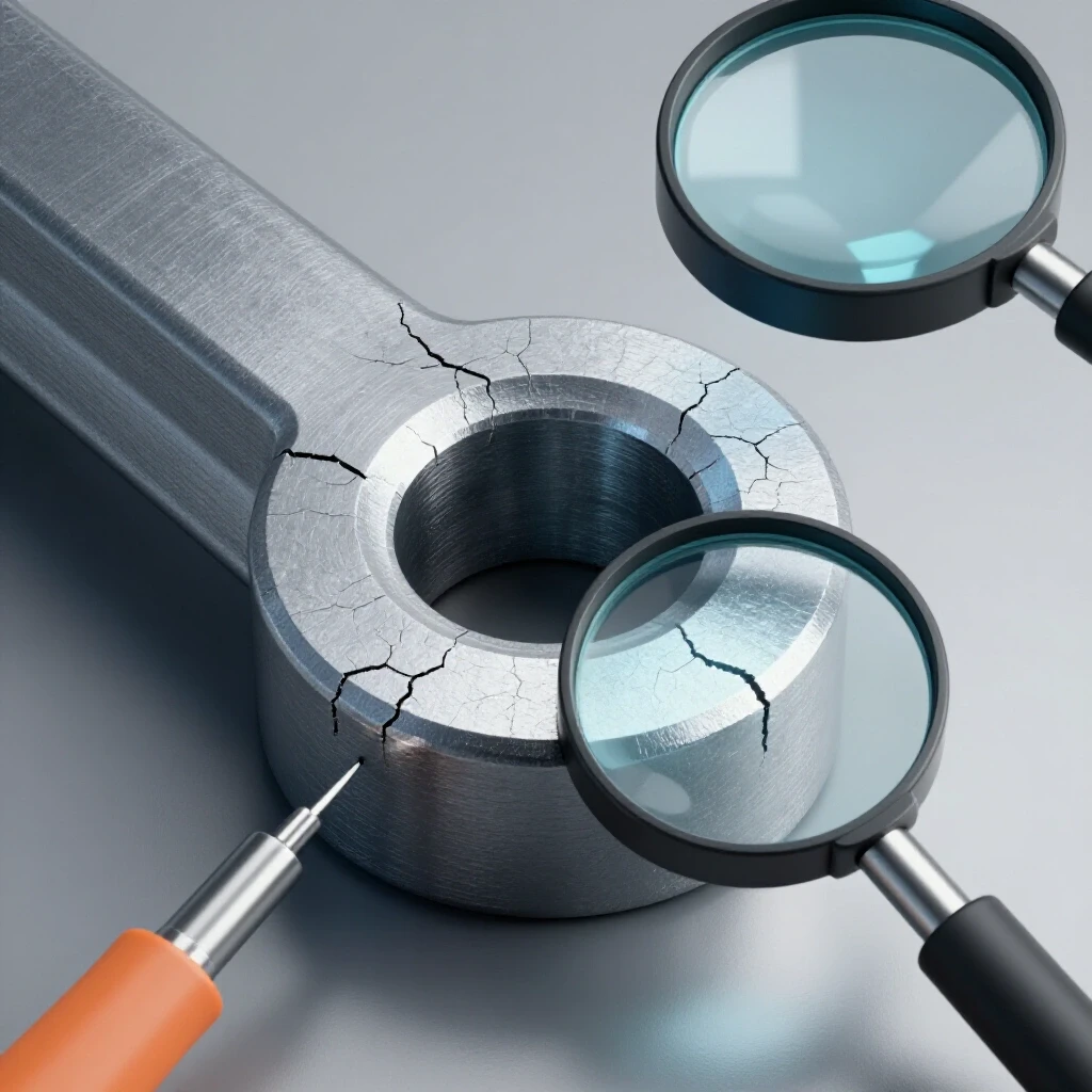
A scribe line is essentially a controlled scratch, and in the world of material science, a scratch can act as a stress riser. A stress riser is a location in a structure where the internal stress is significantly higher than the surrounding area. If a deep scribe line is placed in a high-tension zone of a structural member, it can become the starting point for a fatigue crack.
When I analyze failures in the field, I look for “crack initiation sites.” In a project involving a pressurized vessel or a vibrating frame, a deep etch mark can be dangerous. This is why risk-averse fabricators must balance the need for a visible line with the need to maintain the material’s structural integrity. The Heat Affected Zone (HAZ) of a nearby weld can also interact with these marks. If a scribe line runs perpendicular to a weld bead, the stress concentration at that point increases significantly.
To mitigate this, I recommend using light pressure. You only need to displace enough material to see the reflection of the light in the groove. If you are working on thin-walled tubing (less than 1/8 inch), be especially careful. A deep scratch can reduce the effective wall thickness, creating a “perforation” effect that weakens the tube under bending loads.
Structural Joint Failure Analysis: Layout Errors
| Layout Error | Structural Consequence | Mitigation Strategy |
|---|---|---|
| Over-etching (Deep lines) | Fatigue crack initiation | Use light pressure; sand off marks after layout |
| Mismatched hole centers | Uneven shear stress on bolts | Use a transfer punch after initial scribing |
| Off-square cut lines | Poor fit-up; weld shrinkage | Double-check with a machinist square |
| Scribing in HAZ | Brittle fracture risk | Keep layout marks 1/2″ away from weld toes |
Executing High-Accuracy Layouts: Pressure and Path Control
The physical act of marking steel requires a steady hand and a specific sequence of movements to ensure the line remains true to the measurement. Accuracy is achieved by minimizing the number of variables, such as tool flex, straightedge movement, and parallax error. Parallax error occurs when you view the marking tool from an angle, causing you to perceive its position incorrectly relative to the scale.
I always teach new fabricators to “pull” the scribe rather than “push” it. Pushing a carbide tip can cause it to dig too deep or “chatter,” creating a jagged line that is difficult to follow with a saw or torch. By pulling the tool toward you at a consistent 15-degree angle relative to the surface, you maintain better control over the pressure. I also use a “dead-blow” technique for marking intersections: a single, firm tap on the scribe at the crosshair ensures your drill bit won’t wander later.
One of the biggest mistakes I see in garage fabrication is failing to secure the workpiece. If the steel moves even a fraction of an inch while you are drawing a long line, the entire layout is compromised. Use C-clamps or F-clamps to fix your straightedge to the steel. This allows you to focus entirely on the pressure and path of the carbide tip without worrying about the ruler sliding.
- Step 1: Surface Preparation. Remove all oil, grease, and loose mill scale using a wire brush or a degreaser.
- Step 2: Measurement. Use a certified steel rule. Place the rule on its edge so the graduations are touching the steel to eliminate parallax.
- Step 3: Anchoring. Clamp your straightedge or square firmly to the workpiece.
- Step 4: The First Pass. Draw the scribe toward you with light pressure to “track” the line.
- Step 5: Verification. Check the line against your drawing before making a second, deeper pass if necessary.
Integrating Layout Accuracy into Workshop Safety Protocols
Workshop safety is often discussed in terms of PPE, but it also includes the safety of the final product. A project that is built “out of square” is inherently less stable. When I design shop safety layouts, I ensure that my layout table is at a comfortable height to prevent back strain, which can lead to shaky hands and inaccurate marking.
Handling carbide scribes also requires specific safety awareness. These tools are incredibly sharp and brittle. If you drop a carbide-tipped scribe on a concrete floor, the tip can shatter, sending small, needle-sharp fragments flying. Always wear safety glasses (ANSI Z87.1 rated) even during the layout phase. I have seen more than one “close call” where a fabricator leaned in too close to see a fine line and nearly caught a sharp tool in the eye.
Furthermore, consider the “gas flow” of your workshop. If you are using a scribe to mark lines for a plasma cutter or a welder later, ensure your layout area is separate from your cutting area. Dust and sparks from grinding can settle into your fine scribe lines, making them invisible or causing you to misinterpret a “spark line” for a layout line.
Workshop Safety Checklist for Layout
- Eye Protection: Wear Z87+ clear lenses to see fine lines safely.
- Tool Storage: Keep scribes in a protective sheath when not in use.
- Lighting: Use high-CRI (Color Rendering Index) LED lighting to reduce shadows on the work surface.
- Clamping: Never hold a straightedge by hand if the scribe requires heavy pressure.
- Tip Integrity: Inspect the carbide tip for chips before starting a critical measurement.
Verifying Structural Alignment Before the First Arc
Before you strike an arc and commit to a weld, you must verify that your layout lines have resulted in a square and aligned structure. This is the “measure twice, cut once” philosophy taken to a professional engineering level. I use a technique called “triangulation” or the “3-4-5 rule” to verify that my layout lines have created a perfect 90-degree corner.
In my years of inspecting heavy frames, I’ve found that thermal expansion is the enemy of layout. If you mark your steel while it is sitting in the hot sun and then move it to a cold shop floor, the dimensions can change. For a 10-foot section of steel, a 40-degree Fahrenheit temperature change can result in nearly 1/32 of an inch of movement. While that sounds small, it is enough to make a precision-machined bolt hole bind. Always perform your layout and your fit-up at a consistent temperature.
Once the layout is etched and the parts are cut, I perform a “dry fit.” I align the scribe lines on both mating pieces. If the lines don’t meet perfectly, I don’t “force” the fit with clamps. Forcing a fit introduces “residual stress” into the structure. This is internal tension that stays in the metal even when no load is applied. When you eventually add a real load, the combined stress can exceed the yield strength of the steel, leading to a sudden, brittle fracture.
Structural Load and Stress Tolerances (A36 Steel)
- Yield Strength: 36,000 PSI (The point where steel permanently deforms).
- Tensile Strength: 58,000–80,000 PSI (The point where steel breaks).
- Safety Factor (General): 3:1 (Design for 12,000 PSI).
- Safety Factor (Lifting): 5:1 (Design for 7,200 PSI).
- Layout Tolerance: +/- 0.5mm for structural, +/- 0.1mm for mechanical.
Mastering the use of carbide-tipped tools for steel layout is a journey of discipline. It requires you to slow down and respect the material. By understanding the physics of the scribe, the risks of stress risers, and the importance of thermal stability, you move from being someone who “makes things” to someone who “engineers solutions.” Your projects will not only look better, but they will be fundamentally safer for you and anyone else who relies on them.
The next step in your fabrication journey is to audit your current layout tools. Check your squares for accuracy against a known standard and ensure your carbide tips are sharp enough to catch a fingernail. These small technical details are what separate a failed project from a legacy of solid, reliable craftsmanship.
FAQ: Precision Layout and Material Integrity
Why is a carbide scribe better than a standard steel awl for layout? A carbide scribe is significantly harder than a steel awl, meaning it can displace material on hardened or high-carbon steels where an awl would simply dull. Carbide maintains its sharp point much longer, ensuring your lines remain thin and accurate throughout the entire project.
Can scribe lines cause a structural beam to fail? Yes, if the lines are excessively deep and located in a high-tension zone or a “fatigue-prone” area. These marks act as stress risers where cracks can initiate. Always use the minimum pressure necessary to see the line and avoid scribing in areas that will undergo heavy cyclic loading.
How do I prevent the scribe from “skating” on mill scale? The best way is to remove the mill scale using a flap disc or a wire wheel before layout. If you must mark through scale, use a heavy-duty carbide scribe and apply firm, steady pressure, ensuring your straightedge is clamped securely to prevent any lateral movement.
What is parallax error, and how do I avoid it during layout? Parallax error occurs when your eye is not directly over the measurement mark, causing the line to be drawn slightly to one side. To avoid this, use a thin steel rule and place it on its edge so the markings are flush against the metal surface, and look straight down at the tip of the scribe.
How often should I sharpen or replace my carbide tip? You should inspect the tip under magnification (or a simple jeweler’s loupe) every few projects. If the tip looks rounded or has visible chips, it will produce a wider, less accurate line. Most carbide scribes have replaceable tips, which is more cost-effective than trying to regrind the carbide yourself.
Is it safe to scribe on stainless steel? Yes, but be aware that stainless steel work-hardens. If you make multiple passes with a scribe, the metal in the groove becomes harder and more brittle. This can make the line more prone to cracking if the part is later bent or formed along that layout line.
What PPE is required for layout work? Safety glasses are mandatory. While layout doesn’t produce sparks like grinding, carbide tips are brittle and can shatter if dropped or stressed. Additionally, steel edges can be sharp, so thin, cut-resistant gloves are recommended when handling large sheets or beams.
Does temperature affect layout accuracy? Absolutely. Steel expands and contracts with temperature. If you are working to tolerances of 0.5mm or tighter, ensure your material, your measuring tools, and your shop environment are at a consistent temperature to avoid dimensional drift.
How do I mark a line on a curved steel surface accurately? For curved surfaces, use a flexible steel rule or a custom-made template. Ensure the template is held tight against the contour. A carbide scribe is ideal here because it can follow the curve without the “bleeding” or widening that occurs with other marking methods.
What should I do if I make a mistake and scribe a line in the wrong place? Do not try to “erase” it by scribing over it. Mark the incorrect line with a “X” using a paint marker so you don’t accidentally cut it. If the part is structurally critical, you may need to lightly sand out the incorrect mark to remove the stress riser, provided it doesn’t thin the material too much.
(This article was written by one of our staff writers, James Harlan. Visit our Meet the Team page to learn more about the author and their expertise.)