Manual Bandsaw vs CNC Plasma Cutting for Shops (Comparison)
Scaling a fabrication business from a hobby-level garage into a professional micro-manufacturing facility is a transition filled with technical hurdles. I have spent over 20 years navigating these shifts, moving from basic manual tools to high-output automated systems. The most critical decision often involves choosing between traditional mechanical cutting and automated thermal profiling. This choice dictates your shop layout, electrical needs, and how you move material from the rack to the shipping crate.
When I first integrated a CNC system into my workflow, I underestimated how much it would change my floor plan. My old shop was built around long, linear paths for a saw. When the gantry system arrived, those paths were blocked, and my efficiency actually dropped for three months. I learned the hard way that scaling isn’t just about buying a faster tool; it is about redesigning the entire environment to support that tool.
Analyzing Shop Floor Dynamics for Different Cutting Methods
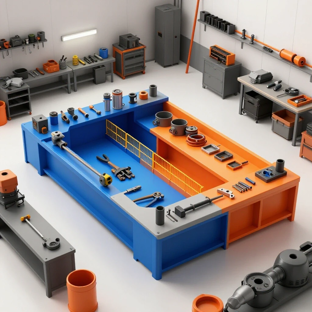
This stage involves evaluating how your choice of equipment dictates the physical movement of raw stock and finished parts within a limited workspace. Your layout must account for the specific footprint and clearance requirements of each machine to prevent production bottlenecks.
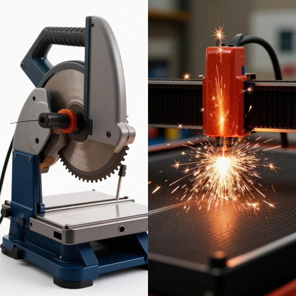
In a traditional setup, a manual tool using a continuous blade loop requires a long, narrow “runway.” You need space for a 20-foot stick of steel to enter the machine and space for it to exit. This creates a linear workflow that usually hugs a wall. If you are cutting long structural members like tubing or channel, this footprint is unavoidable. I often recommend a 3-foot minimum access zone around the operator station to ensure safety and room for blade changes.
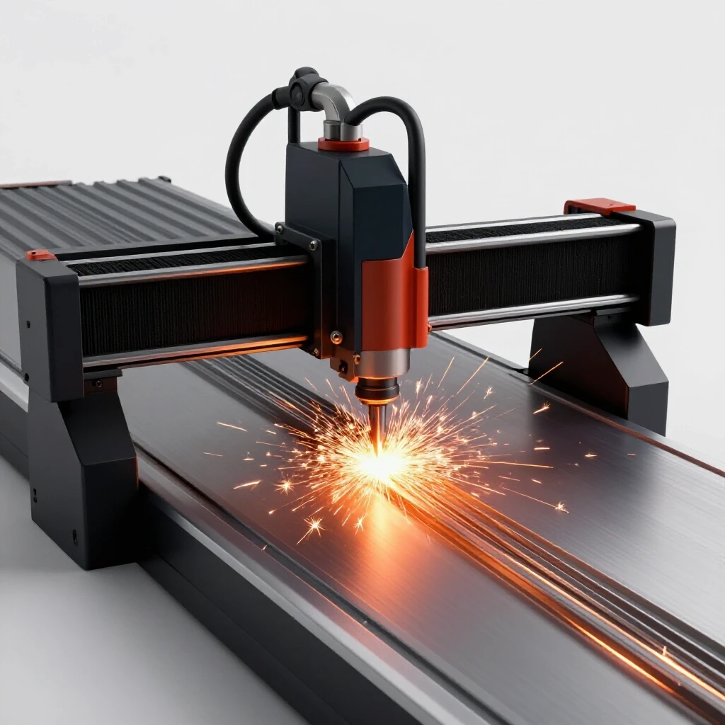
Conversely, an automated system using ionized gas for profiling has a much wider, rectangular footprint. Instead of a linear path, you need a “perimeter” workflow. You must be able to load large 4×4 or 4×8 sheets of plate from at least two sides. In my current shop, I found that placing the table in a central “island” configuration allowed for much faster loading with a jib crane, though it consumed more central floor space.
Workshop Layout Flow Comparison
| Feature | Linear Mechanical Cutting | Automated Thermal Profiling |
|---|---|---|
| Primary Footprint | Narrow and long (e.g., 4′ x 8′) | Wide and square (e.g., 6′ x 10′) |
| Material Entry | End-loading (Long stock) | Side or Top-loading (Sheet/Plate) |
| Clearance Needs | High at ends for long bars | High on sides for sheet handling |
| Operator Zone | Fixed at the machine head | Mobile around the gantry/controller |
| Work Surface | Small vise or table area | Large slat-bed or water table |
Integrating Advanced Motion Systems into Existing Workflows
Transitioning from manual, operator-led cutting to programmed motion control requires a shift in how projects are staged and executed. This involves moving from a “cut-as-you-go” mindset to a “batch-processing” strategy.
When you use a manual saw, the operator is tethered to the machine. The throughput is limited by human presence. In my experience, this creates a “one-at-a-time” bottleneck. You spend 10 minutes measuring, 5 minutes cutting, and 2 minutes deburring. It is a slow, rhythmic process that is easy to manage but hard to scale.
Moving to an automated gantry system changes the labor burden. The work shifts to the front end. You spend time nesting parts and preparing the file, but once the “start” button is pressed, the machine works independently. This allows you to perform other tasks, such as welding or assembly, while the machine profiles the next set of parts. However, the learning curve for motion control—understanding stepper vs. servo motors—can be steep. Stepper motors use discrete steps to move and are cost-effective, while servo motors use closed-loop feedback encoders to ensure the machine knows exactly where it is at all times. For high-output shops, servos are often worth the extra investment because they prevent “lost steps” during a heavy cut.
Powering High-Output Equipment in Small-Scale Facilities
Managing the electrical demands of heavy machinery often requires converting standard residential power into industrial-grade 3-phase supply. This is a common hurdle for home-based fabricators who find that their 200-amp service is insufficient for modern equipment.
Most professional-grade thermal cutting systems and large industrial saws run more efficiently on 3-phase power. If your shop only has single-phase power, you have two main options: a Rotary Phase Converter (RPC) or a Digital Phase Converter (DPC). An RPC uses a physical idler motor to generate the third leg of power. It is robust but can be noisy and less efficient at low loads. A DPC uses solid-state electronics to create perfect 3-phase power, which is better for sensitive CNC electronics but comes with a higher price tag.
In my shop, I balanced my 3-phase loads by grouping machines. I used a 20HP rotary converter to power my larger mechanical tools, while keeping my CNC controller on a dedicated, filtered single-phase circuit to avoid electrical noise. Electrical noise can cause “ghost” triggers in your limit switches, which I found out during a 4:00 AM production run that ended in a gantry crash.
3-Phase Converter Options for Small Shops
| Converter Type | Best Use Case | Efficiency | Noise Level |
|---|---|---|---|
| Rotary (RPC) | Heavy mechanical loads, saws | 85-90% | High (Motor hum) |
| Digital (DPC) | Sensitive CNC electronics | 95-98% | Low (Silent) |
| Static | Light-duty, single-tool use | 60-70% | Low |
| VFD | Single motor speed control | 95% | Low |
Note: Always consult the National Electrical Code (NEC) for local grounding requirements.
Managing Air Quality and Fume Extraction in Confined Spaces
High-heat cutting processes generate particulates and gases that require specific CFM-rated filtration systems to maintain a safe working environment. Unlike the heavy chips produced by a saw, thermal cutting produces fine dust that stays airborne for hours.
A manual saw produces physical chips that fall to the floor. A simple shop vacuum or a chip tray usually suffices. However, when you introduce a process that melts metal, you are dealing with sub-micron particulates. According to OSHA guidelines, maintaining breathable air in a fabrication shop requires high-volume air turnover. For a standard CNC table, you need an extraction system capable of 1,000 to 2,000 Cubic Feet per Minute (CFM).
I recommend two primary methods for fume management: a water table or a downdraft system. A water table traps dust in the water directly under the cut. It is simple and effective but makes the parts messy. A downdraft system uses a powerful fan to pull air through the table and into a multi-stage cyclone dust collector. This keeps the parts dry but requires complex ducting. When designing your ductwork, remember that every 90-degree bend causes “static pressure loss,” which reduces the actual CFM at the table. Use long-sweep elbows and smooth-walled pipes to keep the air moving.
Comparing Structural Rigidity and Material Handling Requirements
The physical weight of the machine and the stock it handles dictates floor load ratings and the need for specialized lifting equipment. A heavy machine is a stable machine, but it also places a permanent burden on your shop floor.
A high-quality manual saw can weigh anywhere from 500 to 2,000 pounds. This weight is concentrated in a small area. Most standard 4-inch concrete shop floors can handle this, but you should check for cracks or settling. Automated tables, especially those with water beds, can weigh significantly more. A 4×8 water table filled with water and a full sheet of 1-inch steel plate can exceed 4,000 pounds.
When I upgraded my layout, I had to reinforce a section of the slab to prevent the gantry from going out of level over time. If your gantry is not perfectly level, your torch height control (THC) will struggle to maintain the correct gap, leading to poor cut quality. I use a precision machinist level (0.0005″ per foot) to check my table every six months.
Air Filtration CFM Requirements by Tool
- Manual Bandsaw: 200–400 CFM (Primarily for fine dust/coolant mist)
- Small CNC Table (2×2): 500–800 CFM
- Standard CNC Table (4×8): 1,200–2,000 CFM
- Heavy Production Table: 2,500+ CFM
Strategic Workflow Optimization Tips for Scaling
To move from a hobby setup to a professional operation, you must treat your shop like a manufacturing cell. This means every movement must be intentional.
- Map your material path: Draw a line on your shop floor showing where a sheet of steel travels from the delivery truck to the cutting table, then to the welding bench. If that line crosses itself or doubles back, your layout is inefficient.
- Standardize your tooling: In my shop, I keep a log of “cut recipes.” This includes the exact speed, height, and power settings for every material thickness. This reduces setup time from 15 minutes to 2 minutes.
- Implement a “Clean Zone”: Keep your CNC electronics and computers in a pressurized cabinet or a separate room. Metallic dust from saws and grinders is conductive and will eventually short out your control boards.
- Optimize 3-Phase Delivery: Use a distribution block after your phase converter. This allows you to run multiple machines off one converter without having to rewire the whole shop every time you add a tool.
Key Takeaways for Shop Evolution
Transitioning your shop is a marathon, not a sprint. The jump from manual mechanical cutting to automated thermal profiling is the single biggest leap you can make in throughput. However, that leap requires a foundation of solid electrical planning and environmental control.
I have found that the most successful shops are those that don’t just add machines, but add systems. If you focus on the flow of material and the quality of your power and air, the machines will perform at their peak. Start by measuring your available amperage and mapping your floor space. Once you understand your constraints, you can make an informed decision on which technology will actually help you scale.
Frequently Asked Questions
How does the “kerf” or cut width differ between these two methods? Mechanical cutting with a blade typically has a kerf of 0.035 to 0.045 inches, which is very predictable. Thermal profiling using ionized gas has a wider kerf, often between 0.060 and 0.080 inches depending on the amperage. This means you must account for more material waste and adjust your part offsets in your design software to maintain dimensional accuracy.
Can I run a CNC plasma table on a standard 50-amp welder circuit? While a 50-amp circuit may power the plasma power supply itself, it often isn’t enough for the entire system. You must also account for the CNC controller, the laptop, the air compressor (which is usually a high-draw item), and the fume extraction fan. Most advanced shops require at least a dedicated 100-amp sub-panel for an automated cutting cell.
Which method provides a better edge finish for immediate welding? A manual saw generally produces a cleaner, square edge that is ready for welding with minimal prep. Thermal profiling leaves a layer of “dross” or slag on the bottom of the cut and a thin layer of nitrides on the edge. While modern high-definition systems have improved this, you will likely spend more time cleaning edges if you switch to thermal cutting.
What is the “duty cycle” and why does it matter for shop scaling? Duty cycle is the amount of time a machine can run in a 10-minute period without overheating. A manual saw often has a 100% duty cycle. Many entry-level thermal power supplies have a 40% to 60% duty cycle. If you are moving to high-volume production, you need a power supply rated for a 100% duty cycle at your desired thickness to avoid mid-cut shutdowns.
How much air pressure do I actually need for automated cutting? It is not just about pressure (PSI); it is about volume (CFM) and air quality. Most systems need 90–120 PSI, but they require a high volume of dry, oil-free air. If your air has moisture, your consumables will wear out in minutes rather than hours. I recommend a refrigerated air dryer for any shop integrating automation.
Does a water table affect the accuracy of the motion system? The water itself doesn’t affect the motion, but the weight of the water requires a much sturdier frame. Additionally, the “splash factor” can lead to corrosion on your linear rails and bearings. You must use a water treatment additive to prevent rust and bacterial growth, and you must keep your rails lubricated daily.
Is it better to buy a turnkey CNC system or build one from a kit? For a professional shop, I almost always recommend a turnkey system. While kits are cheaper, the time you spend troubleshooting and “fiddling” with the machine is time you aren’t producing parts. A turnkey system comes with a warranty and a known set of performance metrics, which is essential for calculating your return on investment.
How do I calculate the “static pressure loss” in my fume extraction? Static pressure is the resistance the fan must overcome to move air through the ducts. You calculate it by adding the “equivalent length” of all your pipes, elbows, and transitions. For example, a 90-degree elbow might add the same resistance as 10 feet of straight pipe. If your static pressure is too high, your 1,500 CFM fan might only move 800 CFM at the table.
(This article was written by one of our staff writers, Edward Sinclair. Visit our Meet the Team page to learn more about the author and their expertise.)