How to Wire a Custom Workshop Emergency Stop Switch (Guide)
I remember standing over a custom-built CNC plasma table three years ago, watching a 1/4-inch steel plate vibrate with a resonance that sounded like a dying cello. The torch was diving into the material, and the motor controller was ignoring my software commands. In that moment, the difference between a minor adjustment and a destroyed gantry was a single physical button. I didn’t have one yet. I had to scramble for the power strip, nearly tripping over a ground lead. That experience taught me that the most important tool in any fabrication shop isn’t the welder or the mill; it’s the ability to kill the power to a failing process instantly.
When we talk about troubleshooting in a professional shop, we often focus on the “how” of making things work. We obsess over 0.002-inch tolerances or the perfect shielding gas flow. But after 15 years in the field, I’ve realized that true diagnostic mastery includes knowing how to safely interrupt a system when it goes sideways. Whether you are dealing with tool chatter that threatens to shatter a carbide insert or a weld pool that is bubbling with porosity, having a dedicated manual override for your low-voltage control circuits is a foundational safety step.
In this guide, we are going to break down the systematic process of integrating a manual safety cutoff into your 12–24V DC equipment. We will look at why these systems fail, how to diagnose electrical gremlins in your control loops, and how to wire a reliable interruption point that works every time.
Establishing a Systematic Diagnostic Framework
A diagnostic framework is a structured way of looking at a problem to find the root cause. Instead of guessing why a motor is stalling or a weld is cracking, you use a process of elimination. This involves observing the failure, isolating the affected system, and testing variables one at a time to see what changes.
Before you ever pick up a wire stripper or a soldering iron, you have to understand the logic of the machine you are modifying. Most shop equipment operates on two levels: the high-power side that does the work and the low-voltage side that does the thinking. When we install a manual kill function, we are almost always working on the “thinking” side. This is the 12V or 24V DC circuit that tells a relay or a motor driver to engage.
Building a diagnostic path starts with a simple question: “What is the smallest part of this system that could be causing the fault?” If a lathe spindle won’t stop, is it the software, the physical switch, or a short in the wiring? By mapping these paths, you avoid the frustration of replacing expensive parts that weren’t broken in the first place.
The Rule of Variable Isolation
Variable isolation is the practice of changing only one thing at a time during a test. If you change the wire gauge and the switch type at the same time, you won’t know which one fixed your voltage drop issue. This method ensures that your repairs are based on data rather than luck.
In my experience, most shop errors come from a combination of mechanical wear and electrical noise. When I’m troubleshooting a motor controller that won’t respond to a stop command, I isolate the control wire from the power leads. If the problem goes away, I know I have electromagnetic interference (EMI). If I had just replaced the switch, I would have wasted two hours and fifty dollars.
Diagnosing Mechanical Baselines and Structural Faults
Mechanical baselines are the “known good” measurements of a machine in its ideal state. This includes things like spindle runout, table flatness, and axis backlash. Knowing these numbers allows you to identify when a machine is vibrating out of spec or when a structural alignment fault is causing tool chatter.
Before you wire in a safety interrupt, you need to ensure the machine itself is mechanically sound. A manual kill switch is a band-aid if your real problem is a loose gib or a worn-out bearing. I once spent a whole day trying to fix a “shudder” in a mill by adjusting the motor drivers, only to find out the mounting bolts for the motor had vibrated loose by 1/16th of an inch.
Identifying and Fixing Tool Chatter Harmonics
Tool chatter is a resonant vibration that happens when the cutting force fluctuates rapidly. It leaves a wavy finish on the metal and can destroy your tooling. Chatter is often a sign that the machine’s rigidity has been compromised or that the speed and feed rates are hitting a natural frequency of the setup.
To solve chatter, you have to change the frequency. This can be done by increasing the rigidity of the workholding or by adjusting the spindle RPM. If you can’t stop the chatter through adjustment, you need that manual kill switch to stop the cut before the tool snaps.
- Check for Backlash: Use a dial indicator to check for movement in the lead screws. Anything over 0.005 inches in a standard manual mill is cause for concern.
- Inspect Spindle Play: Place the indicator on the spindle nose and apply pressure. Movement should be near zero (less than 0.001 inches).
- Calculate Feed-Per-Tooth: Ensure you aren’t “rubbing” the material. For steel, a feed of 0.002 to 0.005 inches per tooth (IPT) is a common baseline to avoid harmonic resonance.
| Factor | Symptom | Diagnostic Fix |
|---|---|---|
| Spindle Speed | High-pitched squeal | Reduce RPM by 10-15% |
| Tool Overhang | Deep, low-frequency rumbling | Shorten the tool stick-out |
| Workpiece Rigidity | Visible vibration in the part | Add more clamps or a bridge |
| Feed Rate | Rubbing or smoking | Increase feed to engage the tooth |
Integrating a Manual Kill Function in Low-Voltage DC Circuits
Integrating a manual kill function involves placing a physical switch into a control circuit to break the flow of electricity. In 12V or 24V DC systems, this usually means interrupting the “Enable” signal on a motor driver or the coil power on a power relay. This ensures that when the button is pushed, the machine loses its “permission” to run.
When you wire these switches, you have two main choices: Normally Open (NO) or Normally Closed (NC). For a safety-critical application, you should almost always use Normally Closed logic. In an NC setup, the electricity flows through the switch to keep the machine running. If a wire breaks or a terminal comes loose, the circuit opens, and the machine stops. This is called “fail-safe” design.
Selecting the Right Switch Behavior
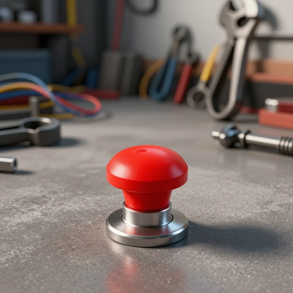
There are two primary behaviors for these switches: momentary and latching. A momentary switch only breaks the circuit while your finger is on the button. A latching switch stays “off” once you press it and requires a physical twist or pull to reset. For a workshop environment, a latching “mushroom head” switch is the standard because it ensures the machine cannot restart unexpectedly.
- Latching Switches: Best for emergency stops. They stay depressed until manually reset.
- Momentary Switches: Better for “jog” functions or temporary pauses.
- Contact Blocks: These are the replaceable parts on the back of the switch. Look for “NC” blocks for your stop circuit.
Step-by-Step Wiring for a 24V DC Control Loop
- Identify the Signal Wire: Locate the 24V DC wire that powers the “Enable” pin on your motor driver or the “V+” on your relay coil.
- Cut and Strip: Cut this wire at a convenient point. Strip 1/4 inch of insulation from both ends.
- Terminal Connection: Connect one end to terminal 1 of your NC contact block and the other end to terminal 2.
- Verify Resistance: Use a multimeter set to Ohms. With the button out, you should see near 0.0 Ohms. When pressed, it should show “OL” (Open Loop).
- Secure the Housing: Mount the switch in a high-visibility, easy-to-reach location, typically at waist height or on the front of the machine stand.
Troubleshooting Weld Porosity and Defect Root Causes
Weld porosity is the presence of tiny holes or “pits” in a weld bead, usually caused by trapped gas. It is one of the most common fabrication errors and can lead to structural failure. When porosity appears, the first reaction is often to turn up the heat, but the solution is usually found in the gas delivery or material cleanliness.
If you are mid-weld and see the puddle start to “boil” or “pepper,” you need to stop immediately. Porosity is often a sign of a failing solenoid or a leak in the gas line. By using a systematic approach, you can isolate whether the issue is atmospheric (a draft in the shop), mechanical (a leaky hose), or metallurgical (dirty base metal).
The Porosity Diagnostic Checklist
When I encounter porosity, I go through a mental “Fault Tree.” I start with the easiest things to check and move toward the more complex. Most of the time, the issue is a simple mechanical failure in the gas delivery system.
- Gas Flow Rate: Check the flowmeter. For MIG/TIG on steel, you want 20 to 30 Cubic Feet per Hour (CFH). Too low and you get no coverage; too high and you create turbulence that pulls in air.
- Nozzle Obstruction: Look for “spatter” inside the shroud. If the gas can’t flow smoothly, it won’t protect the puddle.
- Leaky Fittings: Use soapy water on all connections. Even a tiny leak on the “suction” side of the gas line can pull oxygen into the stream.
- Material Prep: Ensure the steel is ground to bright metal. Mill scale, oil, and moisture are the primary enemies of a clean weld.
| Observation | Potential Root Cause | Fix |
|---|---|---|
| Random “Swiss Cheese” holes | Wind or drafts blowing gas away | Set up a welding screen |
| Holes at the start of the weld | Gas pre-flow is too short | Adjust pre-flow to 0.5 – 1.0 seconds |
| Black soot with holes | Wrong gas (e.g., 100% CO2 on TIG) | Switch to Pure Argon or 75/25 mix |
| Uniform internal porosity | Moisture in the flux or gas | Replace wire spool or check for line condensation |
Advanced Electrical Testing for Workshop Machines
Electrical troubleshooting often feels like chasing “ghosts” because you can’t see the electricity. However, by using a multimeter and following the flow of current, you can pinpoint exactly where a circuit is failing. In 12-24V systems, the most common issues are voltage drops and high resistance caused by poor terminations.
Voltage drop happens when the wire is too thin for the length of the run or when a connection is loose. This can cause motor controllers to “brown out” and behave erratically. If your manual stop switch is located far from the machine, you must ensure the wire gauge is sufficient to carry the signal without losing voltage.
Measuring Resistance and Voltage Drop
To test the integrity of your new stop circuit, you need to measure the voltage at the end of the line while the machine is under load. If you start with 24.0V at the power supply but only see 21.5V at the driver, you have a 2.5V drop. This is a 10.4% loss, which is generally too high for sensitive electronics. Aim for a drop of less than 3%.
- Check Continuity: With the power off, check the resistance from the switch to the driver. It should be less than 0.5 Ohms.
- Test Under Load: Measure voltage at the driver while the motor is running. If it dips significantly, your wire gauge is too small.
- Inspect Grounding: Ensure your DC ground is “clean” and not shared with high-noise components like plasma cutters or old brushed motors.
Real-World Case Study: Resolving Intermittent Spindle Stalls
I once worked on a custom-built CNC mill that would randomly stall during heavy cuts. The owner thought the motor was underpowered. We started by checking the mechanicals. The spindle backlash was a healthy 0.002 inches, and the gibs were tight. Next, we looked at the electronics.
When we looked at the 24V control loop, we found that the stop button was wired with very thin, unshielded wire that ran right next to the 220V AC spindle motor cables. Every time the motor worked hard, it created an electromagnetic field that “tricked” the control loop into thinking the stop button had been pressed for a millisecond.
The fix wasn’t a bigger motor. We replaced the control wire with a shielded 18-gauge twisted pair and moved the manual interrupt switch to its own dedicated circuit away from the power lines. The stalls stopped immediately. This is why systematic isolation is better than throwing parts at a problem.
Maintenance and Calibration Checklist
To keep your shop running without downtime, you should perform a “system health check” every six months. This prevents small issues from becoming catastrophic failures.
- Button Function: Press every manual stop button to ensure the machine dies instantly.
- Terminal Torque: Check that all screw terminals are tight. Vibration in a shop can loosen these over time.
- Lubrication: Ensure lead screws and ways are oiled. Dry ways increase friction, which increases the load on your DC motors.
- Filter Cleaning: Blow out the dust from your electronics enclosures. Metallic dust can bridge connections and cause shorts.
- Indicator Calibration: Use a 1-2-3 block to verify that your dial indicators and calipers are still reading accurately.
Harnessing Modern Diagnostic Tools
While a multimeter is your best friend, modern technology has given us even better ways to “see” problems. Smartphone apps can now act as vibration spectrum analyzers. By placing your phone on a machine base, you can see the specific frequency of a vibration. If the peak is at 60Hz, you know it’s likely electrical. If it’s at a multiple of your spindle RPM, it’s a mechanical balance issue.
Infrared (IR) thermometers are also invaluable. You can scan your motor drivers and wiring. If one wire at the switch is significantly hotter than the others, you have a high-resistance connection that is about to fail. These tools allow us to move from “reactive” repairs to “predictive” maintenance.
Troubleshooting Tool: The Fault Tree
A fault tree is a logic map that starts with the problem and branches out into possible causes. It helps you stay focused when a machine breaks down and the pressure is on to get it back online.
- Problem: Machine won’t start.
- Is there power? Check the 24V supply output.
- Is the stop circuit closed? Check the manual switch for “Continuity.”
- Is the controller receiving the signal? Measure voltage at the “Enable” pin.
- Is the motor jammed? Try to turn the spindle by hand (with power off).
By following this tree, you eliminate 90% of the possible issues in the first five minutes.
Conclusion: Mastering the Controlled Stop
Developing a systematic diagnostic mindset is about more than just fixing broken things; it’s about understanding the “why” behind every movement and every spark in your shop. Integrating a manual safety interruption into your low-voltage DC systems is a perfect project to practice these skills. It requires you to map out your circuits, choose the right logic, and test your results against a baseline.
When you can confidently diagnose a weld defect, isolate a harmonic vibration, or wire a fail-safe control loop, you stop being a “part-swapper” and start being a true fabricator. You’ll spend less time frustrated by “electrical gremlins” and more time producing high-quality work. Remember, the goal isn’t just to make the machine run—it’s to make sure you are the one in control of when it stops.
Frequently Asked Questions
Why should I use 24V DC for my control circuits instead of 12V?
24V DC is less susceptible to voltage drops and electrical noise than 12V. Because the voltage is higher, the current (amperage) required to trigger a relay is lower, which means you can use longer wire runs without losing signal integrity.
What is the best way to mount a manual stop switch on a vibrating machine?
Use a rubber gasket between the switch housing and the machine frame. This dampens the high-frequency vibrations that can cause the internal contacts of the switch to “bounce,” which might lead to accidental shut-offs.
Can I wire multiple stop buttons to one machine?
Yes. To do this with Normally Closed (NC) switches, you must wire them in series. This means the power goes into the first switch, out to the second, and then to the controller. If any one of the switches is pressed, the entire circuit opens and the machine stops.
How do I know if my tool chatter is caused by the machine or the tool?
Perform a “tap test.” Gently tap the tool with a small mallet while it is in the spindle and listen to the ring. Then tap the machine table. If the tool has a high-pitched, long-lasting ring, the issue is likely tool overhang or a loose collet. If the table has a dull thud, the machine is likely rigid enough.
What does “back-EMF” mean in a DC motor circuit?
Back-EMF (Electromotive Force) is voltage generated by a motor when it is spinning, acting like a generator. If you hit a stop button and the motor keeps spinning, that back-EMF can sometimes keep a relay energized for a few seconds. Using a “flyback diode” across the relay coil can help bleed off this energy.
Why does my weld porosity only happen at the end of a bead?
This is often caused by “crater porosity.” When you stop the weld abruptly, the gas coverage disappears while the metal is still molten. To fix this, use a “shielding gas post-flow” of 3 to 5 seconds to keep the puddle protected until it solidifies.
Is it better to interrupt the positive or negative wire in a DC circuit?
It is standard practice to interrupt the positive (hot) wire. This ensures that the component you are turning off is no longer “live” relative to the ground, which reduces the risk of accidental shorts if a wire gets pinched later.
How can I tell if a DC relay has failed internally?
Use your multimeter to check the resistance of the coil. If it shows “OL,” the internal wire has snapped. Then, check the resistance across the contacts while the relay is energized. If it’s more than 0.2 Ohms, the contacts are pitted or burnt and the relay should be replaced.
What wire gauge should I use for a 24V stop switch?
For most control signals (under 1 Amp), 18 AWG or 20 AWG is sufficient. However, if the run is longer than 20 feet, consider 16 AWG to prevent voltage drop. Always use stranded wire in a workshop, as solid wire can crack from machine vibration.
My switch feels “crunchy” when I press it. What should I do?
Replace it immediately. “Crunchiness” usually means metallic dust or grinding grit has entered the housing. In a low-voltage circuit, this grit can act as an insulator or a conductor at the wrong time, making your safety stop unreliable.
(This article was written by one of our staff writers, Paul Whitaker. Visit our Meet the Team page to learn more about the author and their expertise.)