How to Straighten Bent Metal Tubing Without Kinking (Fix)
In my 18 years of troubleshooting industrial fabrication mills and custom setups, I have learned that the most frustrating problems are often the ones that look simple on the surface. A bent structural support or a deformed guide rail might seem like a straightforward fix, but without a systematic approach, you often end up with a kinked, unusable piece of scrap. I have spent years diagnosing everything from motor controller faults to resonant tool chatter, and the logic remains the same: you must isolate the variables and understand the material’s limits before you apply force.
When a critical piece of tubing loses its linear geometry, the natural instinct is to shove it under a hydraulic press and push until it looks right. However, metal has a memory, and it also has a breaking point. In this guide, I will break down the diagnostic and corrective steps I use to restore structural integrity to deformed tubing. We will treat this like any other mechanical troubleshooting process, focusing on precision, internal support, and incremental testing to ensure the material returns to its original state without collapsing.
The Physics of Metal Memory and Deformation
Understanding how metal reacts to stress is the first step in any repair. When tubing bends, the outer wall stretches in tension while the inner wall compresses. If the compression exceeds the material’s ability to displace, the wall collapses inward, creating a permanent structural failure known as a kink. This is why a random “push and pray” method rarely works for precision fabrication.
When I am troubleshooting a machine error, such as a misaligned feed tray or a vibrating spindle, I start by looking at the material properties. Metal tubing is essentially a hollow beam. During a bend, the “neutral axis”—the area in the middle that neither stretches nor compresses—shifts. If you try to reverse this without supporting the walls, the tube will almost certainly buckle. This is similar to how tool chatter solutions require identifying the resonant frequency of a setup; you cannot fix the vibration until you understand what is moving and why.
In my experience, the type of metal dictates the strategy. For example, cold-rolled steel has high internal stresses from the manufacturing process. When it bends, those stresses are redistributed. If you do not account for “springback”—the tendency of the metal to return slightly toward its bent shape after the pressure is released—you will never achieve a true alignment. We handle this by over-correcting in tiny, measurable increments.
Systematic Measurement and Deviation Mapping
Precise repair requires more than a visual check. Using dial indicators and surface plates allows a fabricator to map the exact peak of a bend and the run-out across the entire length. This data ensures that pressure is applied at the precise point of maximum deflection for a true fix. In my metalworking diagnostic guide, I always emphasize that you cannot fix what you cannot measure.
I start by placing the tube on a set of V-blocks on a flat surface plate. By rotating the tube and watching a dial indicator, I can find the “high spot.” I mark this with a fine-point paint pen. I also measure the wall thickness at various points. If the bend is severe, the outer wall may have thinned. If the wall thickness has decreased by more than 10%, the structural integrity is compromised, and the tube should likely be replaced rather than straightened.
Building on this, I create a “deviation map.” I take measurements every two inches along the affected area. This allows me to see if the bend is a simple curve or a complex “S” shape. A complex bend requires a different sequence of pressure points. Just as a lathe alignment checklist requires checking multiple points along the bed, tubing alignment requires a full-scale view of the deformation.
Using Dial Indicators for Precision Alignment
A dial indicator is the primary tool for identifying the “high spot” on a deformed tube. By rotating the workpiece or sliding the indicator along its length, you can quantify the deviation in thousandths of an inch, providing a roadmap for how much force is required for correction. This is the same tool I use for eliminating spindle play or checking for backlash in a lead screw.
When using a dial indicator, I look for the point of maximum “run-out.” Let’s say the needle swings 0.040 inches. This tells me exactly how much the tube has moved from its center axis. I then use this number to calculate my initial press depth. I usually start by pressing the tube back to zero, then adding a small percentage for springback.
| Measurement Point | Indicator Reading (Inches) | Target Correction | Resulting Deviation |
|---|---|---|---|
| 0″ (Start) | 0.000 | N/A | 0.000 |
| 2″ | 0.012 | 0.010 | 0.002 |
| 4″ (Peak) | 0.045 | 0.048 | -0.003 |
| 6″ | 0.015 | 0.012 | 0.003 |
| 8″ (End) | 0.000 | N/A | 0.000 |
Internal Support Strategies to Prevent Wall Collapse
Maintaining the internal diameter of a tube during straightening is critical for preventing kinks. Internal support methods, such as sand packing or using articulated mandrels, provide an outward force that resists the tendency of the tube walls to cave in when external pressure is applied during the realignment process. This is the most overlooked step in mechanical troubleshooting steps for fabrication.
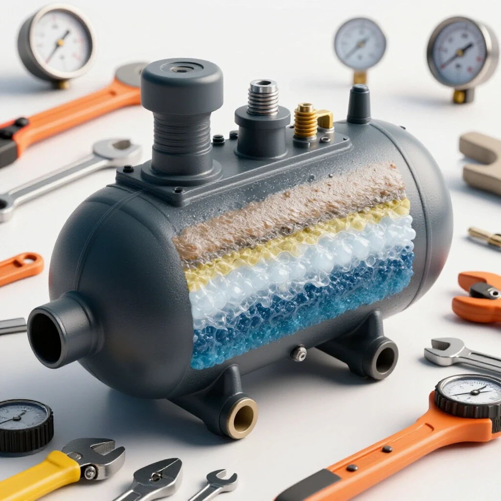
Interestingly, one of the most effective methods for supporting a tube is the “sand-packing” technique. I use fine, dry silica sand. I plug one end of the tube, fill it with sand while tapping the sides to ensure there are no air pockets, and then plug the other end tightly. The sand acts as a non-compressible fluid. When the hydraulic press pushes on the outside, the sand pushes back from the inside, keeping the circular profile intact.
Another professional-grade option is using a mechanical mandrel. These are common in high-end tube bending shops but can be adapted for repair. If you have access to a lathe, you can turn a series of steel plugs that fit snugly inside the tube. By sliding these plugs into the bend area, you provide a solid “anvil” for the metal to press against. This prevents the “oval” shape that often occurs during cold-working repairs.
Sand Packing and Thermal Considerations
Sand packing is a time-tested method that provides uniform internal pressure. By filling the tube with dense, dry material and sealing the ends, you create a solid core that prevents the walls from buckling under external loads. This is particularly useful for thin-walled tubing where the risk of kinking is highest during any structural realignment.
As a result of this internal support, you can sometimes apply a small amount of heat to the “high” side of the bend. I use an infrared heat tracker to ensure I don’t exceed the material’s critical temperature. For standard A36 steel, I stay below 800 degrees Fahrenheit. This “dull red” heat softens the metal just enough to allow the molecules to rearrange without losing their structural properties.
- Ensure sand is 100% dry to avoid steam pressure if heat is applied.
- Use threaded caps or welded end-plates for maximum sand compression.
- Compact the sand using a pneumatic vibrator or by repeated tapping with a dead-blow hammer.
- Verify the internal diameter (ID) with a bore gauge before and after packing.
Incremental Pressure and the Three-Point Method
Applying force in a controlled, step-by-step manner is safer than trying to fix a bend in one heavy press. The three-point method uses two stationary supports and one moving ram. By slowly increasing the load and checking progress, you avoid overshooting the target and causing secondary deformation. This methodical approach is the hallmark of a seasoned diagnostic specialist.
I set up my hydraulic press with two V-blocks spaced widely apart. The further apart the blocks are, the less force is required to move the metal, which reduces the risk of localized crushing. I place the “high spot” of the bend directly under the ram. I use a “soft” interface, like a piece of aluminum or hard rubber, between the steel ram and the tube to prevent marring or surface scarring.
The key here is the “press and release” cycle. I never try to fix it in one go. I press the tube down 0.050 inches, release the pressure, and check the dial indicator. If the tube returns to its original bent position, I haven’t reached the yield point. I then increase the press depth to 0.075 inches and repeat. This iterative process allows me to find the exact point where the metal begins to take a new “set.”
Managing Springback and Yield Points
Springback is the elastic recovery of metal after deformation. To achieve a perfectly straight tube, you must actually bend it slightly past the desired point so that when it “springs back,” it lands exactly at zero. This requires a deep understanding of the material’s yield strength and elasticity, much like diagnosing weld porosity requires understanding gas flow.
In my repair logs, I have noted that stainless steel (like 304 or 316) has significantly more springback than mild steel. If I am working on a 1.5-inch stainless tube with a 0.120-inch wall, I might have to over-bend it by as much as 5 or 10 degrees to get it to stay straight. I always document these values in my maintenance history planner for future reference.
- Measure initial deflection: 0.040″.
- Apply first press: 0.040″ (No permanent change).
- Apply second press: 0.060″ (Tube returns to 0.030″ deflection).
- Calculate recovery ratio: 0.030″ movement for 0.060″ press = 50% recovery.
- Final press calculation: To move the remaining 0.030″, I need to press an additional 0.060″ past the current neutral point.
Case Study: Straightening a 2-Inch DOM Tube Frame
I once had a client bring in a custom-built fabrication jig that had been dropped. The main support was a 2-inch DOM (Drawn Over Mandrel) tube with a 0.188-inch wall. It had a visible “bow” in the center, about 0.125 inches over a 4-foot span. The client was worried about kinking the tube, which would have ruined the entire jig.
I started by isolating the variables. I checked the tube for any signs of cracking or “necking” (where the tube gets thinner in one spot). Finding none, I used the sand-packing method. I filled the tube with kiln-dried sand and capped the ends with heavy-duty expansion plugs. I then set up a 20-ton hydraulic press with the V-blocks spaced 36 inches apart.
Using a digital dial indicator, I monitored the movement. I applied pressure in 0.020-inch increments. Interestingly, the DOM tubing was very stubborn. It took nearly 8 tons of pressure before it even hit the yield point. By carefully tracking the “press vs. return” data, I was able to bring the tube back to within 0.005 inches of perfectly straight over the 4-foot length. This saved the client thousands of dollars in material and downtime.
Troubleshooting Common Errors in the Process
Even with a systematic approach, things can go wrong. One common issue is “secondary bending,” where the tube straightens at the ram point but develops new, smaller bends near the support blocks. This usually happens because the supports are too narrow or the pressure is applied too quickly. It’s similar to how tool chatter solutions often require checking the entire machine’s rigidity, not just the tool bit.
Another issue is surface galling. If the ram is steel and the tube is steel, the high pressure can cause the metals to “weld” together on a microscopic level, leaving ugly scars. I always use a sacrificial shim—brass, copper, or even a thick piece of leather—to protect the workpiece. This is a standard part of my metal fabrication fixes.
Finally, watch out for “work hardening.” Every time you bend and re-bend metal, the grain structure changes. It becomes harder and more brittle. If you over-correct and have to bend it back multiple times, you risk the tube cracking. If I find myself chasing a bend back and forth more than three times, I stop, apply a stress-relieving heat treatment, and let it cool slowly before continuing.
Diagnostic Checklist for Tube Realignment
- Visual Inspection: Check for ripples, cracks, or wall thinning.
- Measurement: Map the bend using a dial indicator and V-blocks.
- Support: Choose the internal support method (Sand, Mandrel, or Plugs).
- Setup: Ensure V-blocks are spaced at least 15-20 times the tube diameter.
- Protection: Place a soft shim between the ram and the tube.
- Incremental Pressing: Move in 0.010″ to 0.020″ increments.
- Verification: Rotate the tube 360 degrees after each press to check for “ovality.”
- Stress Relief: Apply localized heat only if the material is work-hardening.
Tools and Resources for Precision Fabrication
To do this work correctly, you need more than just a hammer and a vise. My diagnostic kit for tube repair includes several high-precision tools that I also use for machine re-alignment and electrical diagnostic readings. Investing in quality measurement tools is the only way to move from “guesswork” to “engineering.”
- Digital Dial Indicator: Look for 0.0005″ resolution for the best results.
- Hydraulic Press: A 12-ton or 20-ton press is sufficient for most shop tubing.
- Infrared Thermometer: Essential for tracking heat-assisted straightening.
- Precision V-Blocks: These must be matched pairs to ensure the tube sits level.
- Bore Gauge: To check that the internal diameter hasn’t collapsed or gone oval.
- Smartphone Vibration Spectrum Analyzer: I use this to check the stability of my press setup during the operation.
By following these mechanical troubleshooting steps, you can recover expensive components and keep your shop running with minimal downtime. The key is to be patient, measure twice, and always support the material from the inside out.
FAQ: Precision Tube Straightening and Diagnostics
How do I know if a tube is too far gone to straighten?
If you see any visible “rippling” on the inside of the bend or if the wall thickness has decreased by more than 10%, the tube has reached its limit. Additionally, if the bend is a sharp “V” rather than a smooth curve, the metal has likely exceeded its ultimate tensile strength, and any attempt to straighten it will result in a kink or a crack.
Can I use a torch to help straighten a tube?
Yes, but you must be careful. Localized heating on the “long” side of the bend (the outside) can help the metal compress as it cools. This is known as flame straightening. However, you must keep the temperature below the material’s critical point (usually around 800-1000°F for mild steel) to avoid changing the grain structure or making the metal brittle.
Why does my tube keep kinking even when I’m being careful?
Kinking usually happens because of a lack of internal support. If the tube walls are thin compared to the diameter, the compression side will always want to buckle inward. Ensure you are using a dense, compacted filler like dry sand or a solid internal mandrel. Also, check that your support blocks are spaced far enough apart; narrow supports concentrate stress too quickly.
What is the best way to measure “straightness”?
The most accurate way is to place the tube on two matched V-blocks on a precision surface plate. Use a dial indicator on a magnetic base. As you rotate the tube, the needle will show the total indicated run-out (TIR). Half of the TIR is your actual deviation from the center line.
Does the type of sand matter for sand packing?
Yes. Use clean, dry, fine-grain silica sand. Do not use play sand or beach sand, as they often contain moisture or organic material that can create steam pressure if you apply heat. The finer the grain, the better the sand will flow into the small gaps and provide uniform support.
How do I account for springback in different materials?
Mild steel typically has a springback of 2-5%, while stainless steel and certain aluminum alloys can have 10-15% or more. The only way to be sure is to use an incremental approach. Press a little, measure the return, and calculate the “elasticity ratio” for that specific piece of material.
Can I straighten square or rectangular tubing using these methods?
Yes, but square tubing is more prone to “oil-canning,” where the flat faces bulge or sink. You must use flat-faced support blocks that cover the entire width of the tube to distribute the pressure evenly across the corners, which are the strongest parts of the profile.
What is “work hardening” and how do I avoid it?
Work hardening occurs when you deform metal at room temperature, causing the crystal structure to become more rigid. If you bend a tube back and forth too many times, it will become brittle and snap. Avoid this by making your corrections in as few steps as possible and using heat to “relax” the metal if it becomes noticeably harder to move.
Should I weld the ends shut when sand packing?
For heavy-duty straightening, welding a temporary plate on the ends is the best way to ensure the sand stays under high compression. However, for lighter jobs, heavy-duty threaded caps or expanding mechanical plugs are usually sufficient. Just make sure the plugs cannot pop out under pressure.
How does this process relate to troubleshooting weld porosity or tool chatter?
All of these issues require a “root cause” analysis. Just as you check shielding gas flow for porosity or spindle rigidity for chatter, you must check material integrity and support for tube straightening. It’s about identifying the weak point in the system and reinforcing it before applying force.
(This article was written by one of our staff writers, Paul Whitaker. Visit our Meet the Team page to learn more about the author and their expertise.)