Digital Job Tracking Sheets for Custom Fabrication (Review)
I have spent more than two decades in the shop, moving from a corner of a garage to a fully integrated manufacturing space. In those early years, managing a few custom brackets or a single gate frame was simple enough to keep in my head. However, as my shop evolved into a high-output environment with CNC machinery and tighter deadlines, the mental load became a significant bottleneck. Scaling a fabrication business introduces a unique kind of stress that physical skill alone cannot solve. It requires a shift from being a craftsman to becoming a systems engineer who views every square foot of the floor and every minute of the day as a resource to be optimized.
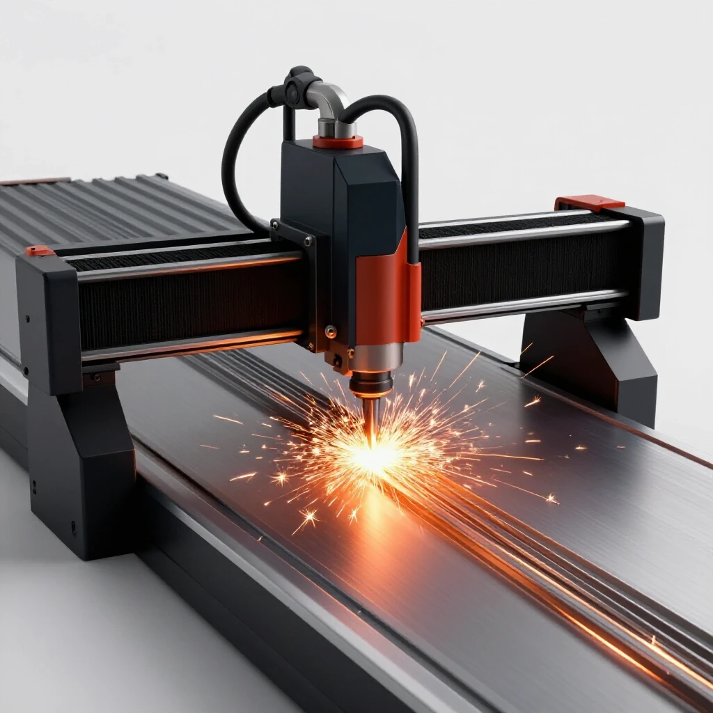
The transition to a semi-professional operation often fails not because of poor welding or cutting, but because the shop’s “nervous system”—the way we track jobs and move material—cannot keep up with the machines. When I integrated my first CNC plasma system, I quickly realized that the speed of the machine was irrelevant if I spent twenty minutes looking for the correct revision of a cut list or moving a pile of plate steel twice to get to the table. This guide focuses on the intersection of physical shop layout and the digital systems used to log job stages, ensuring that your workflow is as precise as your cuts.
Mapping Material-Flow Loops and Electronic Status Tracking
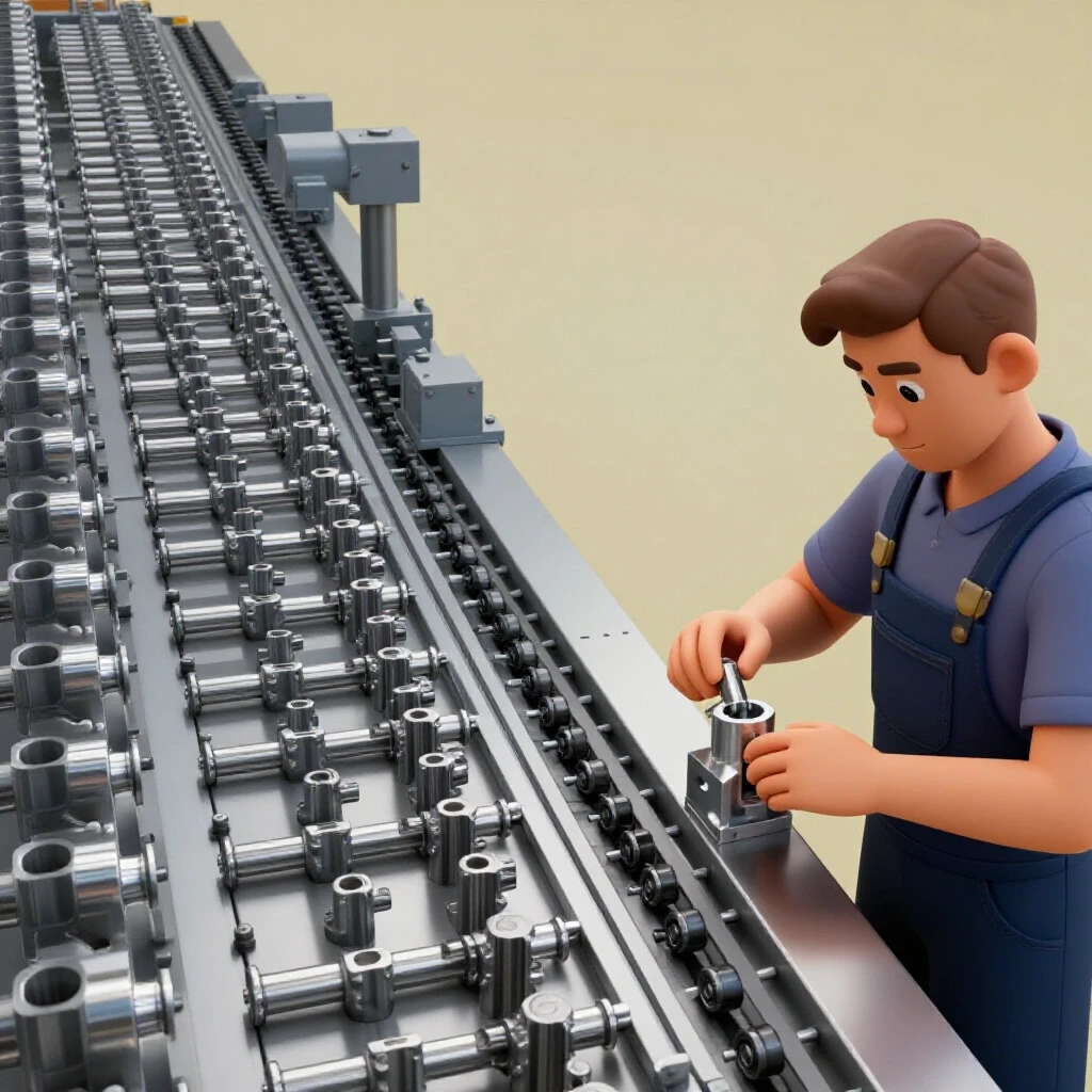
Mapping material-flow loops involves documenting the physical path a raw piece of steel takes from the moment it enters the shop until it leaves as a finished product. By visualizing these paths, you can identify “spaghetti patterns” where material crosses its own path, leading to congestion and safety risks.
In a high-output shop, every time you touch a piece of material, it costs you money. I remember a specific contract for fifty industrial equipment enclosures where I realized my team was walking nearly three miles a day just moving parts between the saw, the plasma table, and the welding station. We were busy, but we weren’t being productive. To fix this, we started using an electronic spreadsheet to log exactly where each part was in the production cycle. This allowed us to see that the bottleneck wasn’t the machines; it was the “dead time” between stations.
A linear flow pattern is the goal for any advanced workshop layout. Raw material should enter near the primary cutting station, move to secondary processing like grinding or bending, then to assembly, and finally to finishing and shipping. By using a digital log to record the completion of each stage, you create a real-time map of your shop’s capacity. If the log shows twenty brackets are stuck at the “Deburring” stage, you know exactly where to reallocate your effort for the afternoon.
| Layout Type | Material Travel Distance | Bottleneck Risk | Information Visibility |
|---|---|---|---|
| Traditional Hobby Setup | High (Circular/Random) | Extreme | Low (Memory-based) |
| Functional Zone Layout | Moderate (Grouped) | Moderate | Medium (Whiteboards) |
| Linear Lean Flow | Low (Straight Line) | Low | High (Digital Logs) |
Measuring Floor Capacities and Machine Zoning
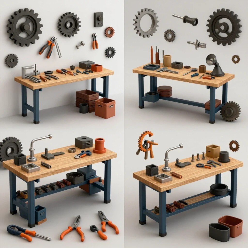
Machine zoning is the practice of grouping equipment by function and utility requirements while maintaining safe “buffer zones” for material handling and maintenance. Floor load ratings are also critical, as industrial machinery and heavy steel racks can exceed the capacity of standard residential concrete slabs.
When I installed my 5×10 CNC plasma table, I didn’t just consider where it would fit; I had to consider the “swing zone” of the material handling equipment. A standard 4-inch reinforced concrete slab can usually handle about 4,000 to 5,000 pounds per square inch (PSI), but a concentrated load from a heavy gantry or a vertical rack of plate steel can cause cracking over time. I now maintain a 3-foot minimum access zone around all major equipment. This ensures that if a motor fails or a lead screw needs greasing, I don’t have to dismantle half the shop to reach it.
Zoning also plays a role in how you log your work. By assigning a digital “station ID” to each area of the shop in your tracking sheet, you can monitor the health of your workflow. If your electronic logs consistently show a delay at the “Bending” station, it might indicate that the area is too cramped for the size of the frames you are building. This data-driven approach takes the guesswork out of shop reorganization.
- Primary Cutting Zone: Minimum 10×15 feet for a standard plasma table.
- Material Intake: Located near a roll-up door to minimize forklift travel.
- Assembly Area: Heavy-duty, leveled tables with dedicated 120V/240V drops.
- Safety Buffers: 36 inches of clear space around all electrical panels and moving gantries.
Analyzing Power Limits and 3-Phase Converter Strategies
A 3-phase power converter is a device that allows industrial machinery designed for three-phase electricity to run on standard single-phase residential or light commercial service. This is often the biggest hurdle for fabricators moving from hobby-grade tools to professional-grade equipment.
Most home-based shops are limited to 200-amp single-phase service. When you start adding a 60-amp plasma cutter, a 5-horsepower air compressor, and a CNC controller, you quickly run out of “headroom.” I learned this the hard way when I tried to run a large ironworker and a dust collector simultaneously, tripping the main breaker and crashing my CNC mid-cut. To solve this, I researched rotary phase converters (RPCs) versus variable frequency drives (VFDs).
An RPC is essentially a large idler motor that generates the third leg of power. It is robust and can handle the high startup surges of industrial motors. However, you must monitor your phase balance. Using a digital log to record voltage across all three legs during a “load test” is vital. If the voltage between any two legs varies by more than 5%, you risk overheating your expensive CNC motors.
| Converter Type | Best Use Case | Cost Factor | Technical Difficulty |
|---|---|---|---|
| Static Converter | Small motors, light duty | Low | Low |
| Rotary Phase Converter | High-surge machinery, CNC | Medium | Moderate |
| Variable Frequency Drive | Single-motor speed control | Moderate | High (Programming) |
Designing High-Volume Clean Air Filtration and Ducting
Dust collection duct design is the engineering of a vacuum system to move air at a specific velocity to capture metal dust, smoke, and fumes. In a fabrication shop, air quality management is not just about comfort; it is about protecting your lungs and preventing fine metallic dust from shorting out your electronic controllers.
A CNC plasma table generates a massive amount of fine particulate. I found that a standard “shop vac” or a small woodworking collector is useless here. You need a system capable of moving 1,000 to 2,000 Cubic Feet per Minute (CFM). The physics of air movement are unforgiving; every 90-degree elbow in your ductwork adds “static pressure loss,” which acts like a brake on your airflow. I designed my system using 6-inch main lines to keep the air velocity high enough to prevent dust from settling in the pipes.
In my tracking sheets, I include a maintenance log for filter changes and bin emptying. If you are cutting a high volume of 1/4-inch plate steel for custom enclosures, your filtration load will be much higher than when doing thin-gauge bracket work. Tracking the “arc-on time” from your digital job logs helps you predict when the filters will reach their capacity, preventing a sudden drop in air quality mid-shift.
- Duct Velocity: Maintain 3,500 to 4,000 feet per minute (FPM) for metal dust.
- Filtration Level: HEPA or sub-micron secondary filters are mandatory for plasma smoke.
- Static Pressure: Minimize long runs and flexible hosing to reduce resistance.
- Make-up Air: Ensure the shop has a way to replace the air being exhausted to avoid back-drafting heaters.
Leveling CNC Plasma Lines and Tooling File Management
Leveling a CNC gantry involves ensuring the rails are perfectly parallel and the bed is flat within a few thousandths of an inch. Even a slight twist in the frame can lead to parts that are out of square or “dross” (hardened slag) that is difficult to remove.
When I first set up my gantry, I used a standard level and thought it was “good enough.” I was wrong. My first batch of twenty-five precision brackets had a slight taper that made assembly a nightmare. I had to go back, use a machinist’s level, and shim the legs until the rails were dead-on. This taught me that automation doesn’t replace precision; it demands it.
Part of this precision involves how you manage your digital tooling files. In a custom fabrication environment, you might have five different versions of a single frame design. If you use an electronic log to track which file version was used for which job number, you eliminate the risk of cutting an obsolete design. This “version control” is a hallmark of an advanced shop. It ensures that if a customer calls six months later for a replacement part, you can pull up the exact digital record and replicate the part perfectly.
- Foundation Check: Ensure the floor is stable and not prone to vibration.
- Rail Alignment: Use a dial indicator to check for parallelism along the entire length.
- Squaring the Gantry: Use the “3-4-5” method or a large precision square to ensure the X and Y axes are 90 degrees apart.
- Z-Axis Calibration: Verify that the torch height control (THC) is reacting correctly to material warping.
Synchronizing Production Logs with Shop Workflow
The real power of using electronic logs is the ability to see the “big picture” of your manufacturing operation. In a micro-manufacturing setup, you are the manager, the operator, and the quality control inspector. It is easy to lose track of small details when you are focused on a complex weldment.
I use a simple digital tracking system where every job is assigned a unique ID. This ID follows the material through the shop. When the raw steel is cut on the plasma table, the log is updated. When it moves to the welding station, it’s updated again. This allows me to calculate my “throughput efficiency.” If I see that a specific type of enclosure consistently takes four hours longer than estimated, I can look at my shop layout and see if the bottleneck is a physical one, like a lack of table space, or a process one, like poor file preparation.
This data-driven approach helped me realize that my “scaling” problem wasn’t a lack of tools, but a lack of organization. By integrating digital status updates into my daily routine, I reduced my setup times by nearly 30%. I no longer spend the first hour of the morning wondering what needs to be done; the log tells me exactly where I left off and what the priority is.
Transitioning to Advanced Operations: A Practical Framework
Moving from a hobby setup to a semi-professional space requires a disciplined approach to both your physical environment and your information management. You cannot simply buy your way into efficiency; you have to engineer it.
Start by performing a “walking audit” of your shop. Take a piece of chalk and draw the path you take to build a common part, like a simple mounting bracket. If the lines look like a tangled ball of yarn, your layout is killing your productivity. Once you have a cleaner physical flow, implement a basic electronic log to track your job stages. Don’t make it overly complex; just focus on the date, the job ID, the current stage (Cut, Bend, Weld, Finish), and any notes on revisions.
As you integrate more advanced technology like CNC plasma and 3-phase power, these digital records become your most valuable tool for troubleshooting. They provide the “before and after” metrics that prove whether an expensive upgrade actually improved your bottom line. Success in custom fabrication is found in the balance between the grit of the shop floor and the precision of the digital record.
FAQ
What is the best way to start tracking jobs digitally without it being a distraction? Start with a very simple electronic spreadsheet. Only track four things: Job Name, Current Station, Deadline, and Material Status. Update it once in the morning and once before you leave. The goal is to build the habit of documentation without adding significant overhead to your workday.
How do I know if my shop floor can handle a heavy CNC table? Check the thickness of your concrete. Most modern residential garages have 4 inches of 3,000 to 4,000 PSI concrete. This is generally sufficient for a 5×10 plasma table, but you should avoid placing heavy material racks directly next to the table legs to prevent localized stress cracks. If in doubt, use steel spreader plates under the machine feet to distribute the load.
Why is 3-phase power so important for scaling a shop? Industrial motors found in large saws, ironworkers, and high-end compressors are significantly more efficient and durable than their single-phase counterparts. 3-phase power provides more consistent torque and allows you to run larger equipment that would otherwise trip standard residential breakers.
What is the most common mistake in shop layout? The most common mistake is placing the material storage too far from the primary cutting station. Moving 4×8 sheets of 1/4-inch steel across a crowded shop is dangerous and time-consuming. Always place your heaviest raw materials as close to the entry point and the first machine as possible.
How much airflow do I really need for a CNC plasma table? For a standard 4×4 or 5×10 table, you should aim for at least 1,500 CFM at the source. If you are using a water table, you can get away with less, but for dry downdraft tables, high volume is required to capture the fine dust before it escapes into the rest of the shop.
Can I run a CNC controller on the same circuit as a phase converter? It is generally not recommended. CNC controllers are sensitive to electronic noise and voltage fluctuations. It is best to run your controller and computer on a dedicated, filtered single-phase circuit, while the phase converter handles the heavy motor loads like the vacuum or the compressor.
How do digital logs help with material waste? By logging the “remnants” or off-cuts of expensive sheets in your digital sheet, you can quickly check if you have a piece of scrap that fits a small job before cutting into a fresh 4×8 sheet. This “remnant tracking” can save hundreds of dollars a month in material costs.
What is “static pressure” in a dust collection system? Static pressure is the resistance the air encounters as it moves through pipes, bends, and filters. Think of it like friction in a water pipe. The more bends and the smaller the pipe, the harder the fan has to work to move the same amount of air. Keeping runs short and using large-diameter smooth-wall pipe is the best way to maintain high CFM.
How often should I calibrate my CNC gantry? For a high-output shop, a quick check once a week is good practice. A full calibration using a machinist’s level and dial indicators should be done every few months or whenever you notice a slight drift in part accuracy.
Is an electronic log better than a whiteboard? A whiteboard is great for immediate “at-a-glance” status, but it doesn’t provide a history. An electronic log allows you to look back at jobs from months ago to see how long they took, what materials were used, and what issues occurred. This historical data is essential for accurate bidding on future projects.
(This article was written by one of our staff writers, Edward Sinclair. Visit our Meet the Team page to learn more about the author and their expertise.)