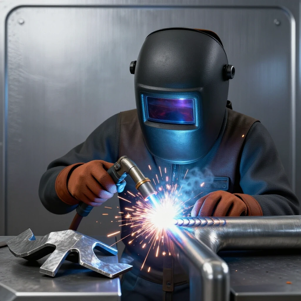
How to Calculate Structural Load Capacity for Steel (Guide)
I remember the first heavy-duty workbench I built nearly fifteen years ago. I had used thick-walled square tubing and assumed that because the steel was heavy, the bench could support anything I threw at it. A few months later, after placing a vintage 400-pound lathe on the center span, I noticed a subtle but terrifying dip in the frame. That was my first real lesson in the difference between “looking strong” and being structurally sound. In the years since, working through mechanical engineering problems and thousands of hours on the shop floor, I have learned that steel follows strict physical laws that do not care about our gut feelings.

When you are building projects in a home shop or a small fabrication bay, the anxiety of a structural failure is a healthy motivator. It pushes us to look past the surface of a clean weld and consider how the metal itself handles the forces of weight and gravity. My goal is to help you move from guesswork to a data-driven approach. We will look at how to evaluate the internal limits of your materials, recognize where heat changes your steel’s DNA, and set up a workspace that keeps you safe while you push these limits.
Understanding the Physical Limits of Mild Steel
Before we can estimate what a frame can hold, we have to understand what the metal is doing on a molecular level under pressure. Steel is popular because it is predictable, but that predictability only exists if you stay within its elastic range.
Yield strength is the point where steel stops acting like a spring and starts acting like modeling clay. For common A36 mild steel, this is typically around 250 MPa, or roughly 36,000 PSI. If you apply weight that stays below this number, the steel will bend slightly and then return to its original shape when the weight is removed. However, if you cross that yield point, the metal undergoes “plastic deformation.” It stretches permanently, thinning out and losing its ability to support the load. In a workshop setting, we never want to approach the yield point. We want to operate well within the safety margins to account for human error in welding or slight variations in material quality.
Common Material Properties for Workshop Steel
| Property | Metric Value | Imperial Value | Why it Matters |
|---|---|---|---|
| Yield Strength (A36) | 250 MPa | 36,000 PSI | The limit before permanent bending occurs. |
| Tensile Strength | 400–550 MPa | 58,000–80,000 PSI | The point where the metal actually tears apart. |
| Density | 7,850 kg/m³ | 0.284 lb/in³ | Helps you calculate the self-weight of the structure. |
| Modulus of Elasticity | 200 GPa | 29,000,000 PSI | Determines how much the steel will deflect or “sag.” |
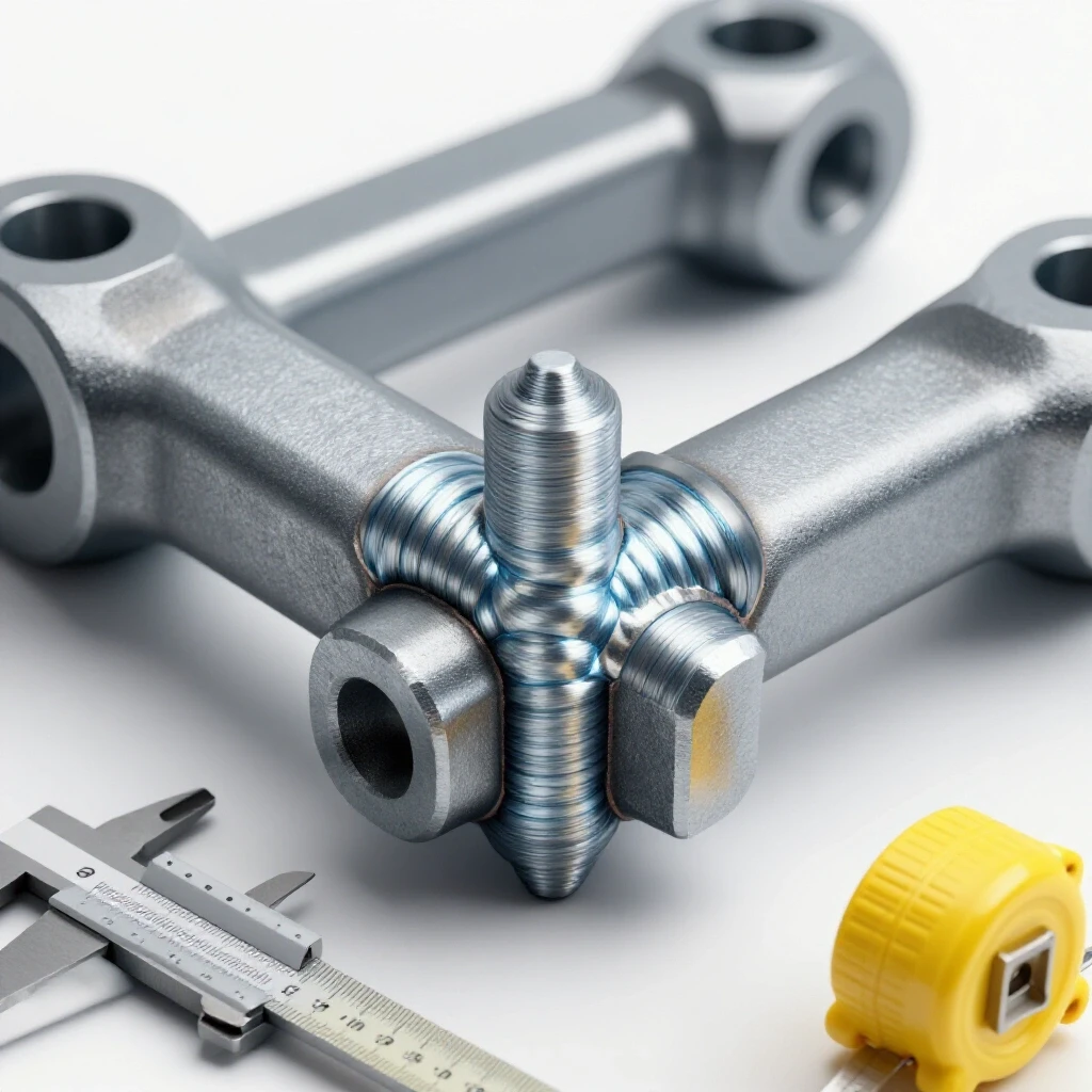
Building on this, we must also consider the “Heat-Affected Zone” or HAZ. This is the area of metal surrounding your weld that didn’t melt but got hot enough to change its internal grain structure. In many cases, the HAZ is actually the weakest point of your project. If you over-weld a joint or use too much heat, you can effectively “anneal” the steel, making it softer and more prone to bending right next to your beautiful, strong weld bead.
Why Geometry Dictates Weight Distribution
The shape of the steel you choose is often more important than the thickness of the walls. I have seen 2-inch C-channel fail under loads that a 2-inch square tube handled with ease, simply because of how the shapes resist twisting and bending.
When you place a load on a horizontal beam, the top of the beam is being squeezed (compression) while the bottom is being pulled apart (tension). The material in the very middle of the beam is doing almost nothing to support the weight. This is why I-beams and hollow square tubes are so effective; they put the most material at the top and bottom edges where the stress is highest. When you are planning a shop project like a gantry or a heavy shelf, choosing a shape with a high “Moment of Inertia”—a mathematical value representing a shape’s resistance to bending—is your best defense against failure.
Evaluating Shape Performance in Shop Projects
- Square and Rectangular Tubing: These are excellent for most workshop builds because they resist “torsion” or twisting. If your load isn’t perfectly centered, tubing stays stable.
- Angle Iron: While easy to weld, angle iron is prone to twisting under heavy loads. I generally limit its use to bracing or short spans where the weight is under 100 kg.
- C-Channel: This is great for heavy frames, but it must be braced to prevent the “flanges” from folding inward or outward under extreme pressure.
- Flat Bar: Never use flat bar as a primary load-bearing beam. It has almost no resistance to bending when placed on its flat side.
Interestingly, the span length is the most aggressive variable in your design. If you double the length of a beam, you don’t just double the sag; you increase it by a factor of eight. This is why a four-foot workbench might feel rock solid, but an eight-foot bench with the same steel feels “bouncy.”
Identifying Internal Weld Defects That Compromise Strength
A frame is only as strong as its weakest joint. During my years of inspection, I’ve found that the most dangerous failures aren’t caused by the steel breaking, but by the welds “unzipping.” This happens when the weld looks good on the outside but lacks internal integrity.
One of the most common issues is “lack of fusion.” This occurs when the weld metal sits on top of the base metal without actually melting into it. It’s like using hot glue instead of a proper bond. Another silent killer is “porosity,” which shows up as tiny bubbles in the weld. Porosity is usually caused by a poor welding gas flow rate. If your gas flow is too low (below 15 CFH) or there is a draft in your shop, the shielding gas is blown away, allowing oxygen to contaminate the molten puddle and turn it into a brittle, “Swiss cheese” structure.
Common Weld Defects and Structural Impacts
| Defect | Visual Indicator | Structural Consequence | Corrective Action |
|---|---|---|---|
| Undercut | A groove melted into the base metal at the edge of the weld. | Creates a “stress riser” where cracks start. | Lower your travel speed and hold the edges longer. |
| Porosity | Small pinholes or “sponge-like” appearance. | Drastically reduces the load-bearing area. | Check gas flow (aim for 18–20 CFH) and clean the steel. |
| Incomplete Penetration | The weld doesn’t reach the bottom of the joint. | The joint can snap under sudden impact. | Increase amperage or open the gap between pieces. |
| Cold Lap | The weld metal “rolls over” the edge without fusing. | The joint has zero structural value. | Increase heat and ensure the arc is on the leading edge. |
As a result of these risks, I always recommend a “visual inspection checklist” before you ever put weight on a structure. Look for a consistent “stack of dimes” appearance in TIG or a smooth, slightly convex ripple in MIG. If the weld looks “cold” or ropey, it likely hasn’t bonded correctly.
Practical Steps for Estimating Load Capacity
While I cannot provide certified engineering formulas for critical structures, we can use a conservative “shop rule” for non-critical items like tool stands or storage racks. For projects intended to hold less than 500 kg (about 1,100 lbs), we can use a basic safety margin of 4:1. This means we design the structure to theoretically handle four times the weight we actually plan to put on it.
To begin your analysis, you must identify the “load path.” This is the route the weight takes from the top of the structure down to the floor. Ideally, weight should travel directly through vertical columns. If the weight is sitting in the middle of a horizontal beam, that beam is under “flexural stress.”
A Step-by-Step Workshop Load Analysis
- Calculate the Total Static Load: Add up the weight of the equipment, the material you might put on it, and the weight of the steel frame itself.
- Identify the Weakest Point: This is usually the center of the longest horizontal span or a joint that is under “shear” (a force trying to slide the metal apart).
- Apply the 4:1 Safety Factor: If your lathe weighs 200 kg, plan your material selection as if it weighs 800 kg.
- Check for Deflection: Use a straightedge. If the beam bows more than 1/360th of its length under the intended load, it is too weak. For a 3-foot (36-inch) span, that’s only 0.1 inches of acceptable sag.
- Verify Support Conditions: A beam that is welded solid at both ends is significantly stronger than a beam just sitting on top of two posts.
Always remember that these estimates are for “static loads”—things that sit still. If you are building something that moves, vibrates, or catches a falling weight, the forces are much higher, and you should seek professional design assistance.
Workshop Safety Protocols and PPE Integration
Calculating weight limits is pointless if you get injured during the fabrication process. Shop safety is about more than just wearing glasses; it is about creating an environment where mistakes don’t become tragedies.
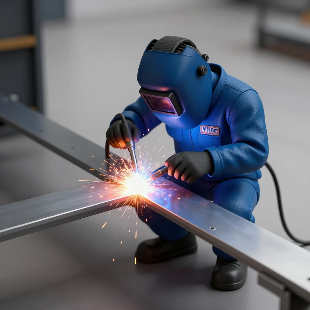
When welding these heavy frames, your PPE (Personal Protective Equipment) is your first line of defense. For structural welding, I recommend a welding helmet with a Shade 10 to 13 filter, depending on your amperage. If you are pushing high heat into thick steel, the infrared radiation is intense. Furthermore, ensure your workspace is laid out to prevent “crush zones.” If a heavy frame is on jack stands, I always use a secondary “catch” system—like wooden cribbing—just in case a stand fails or gets bumped.
Essential Workshop Safety Checklist
- Fire Prevention: Keep a 10-pound ABC fire extinguisher within reach. Clear all sawdust and rags from a 35-foot radius (per OSHA standards).
- Fume Management: Use a fume extractor or a high-volume fan to pull smoke away from your face. Never weld on galvanized steel without a respirator.
- Gas Safety: Ensure your shielding gas cylinders are chained to a wall or a sturdy cart. A falling cylinder can become a rocket if the valve shears off.
- Electrical Safety: Inspect your ground clamp and lead cables for cracks or exposed copper. A poor ground causes inconsistent arcs and weak welds.
- Lighting: Use high-output LED shop lights. If you can’t see the “toe” of the weld puddle clearly, you are guessing, not welding.
Diagnostic Inspection and Load Testing
Once the fabrication is complete, how do you verify it safely? I never recommend just “loading it up and seeing what happens.” That is a recipe for a collapsed structure and a trip to the hospital. Instead, we use a controlled, incremental testing method.
Start by measuring the “unloaded” height of your structure at several points using a precision caliper or a dial indicator. Add weight in small increments—perhaps 25% of the intended load at a time. After each increment, measure the deflection. If the deflection stops being “linear” (meaning the sag starts increasing faster than the weight you’re adding), you have reached the yield point. Stop immediately and unload the structure.
Modern Non-Destructive Testing (NDT) for the Home Shop
You don’t need a million-dollar lab to check your work. I often use “Dye Penetrant” kits, which consist of a cleaner, a red dye, and a white developer. You spray the dye on a cleaned weld, wipe it off, and then apply the developer. If there is a crack—even one invisible to the eye—the red dye will bleed out into the white powder. This is an excellent way to check critical joints on a workbench or engine stand before you trust them with a heavy load.
Additionally, smart welding helmets now offer “grind modes” and “memory settings” that allow you to switch between low-amp tacking and high-amp structural passes without lifting your hood. This keeps your eyes protected while ensuring you have the visibility needed to avoid the defects we discussed earlier.
Final Thoughts for the Risk-Averse Fabricator
Building with steel is a rewarding craft, but it demands respect for the forces involved. By understanding yield strength, choosing the right shapes, and maintaining strict welding standards, you can create shop fixtures that last a lifetime. Never be afraid to “over-build” a non-critical project. If a calculation says 1/8-inch wall tubing is enough, but 3/16-inch is available, the peace of mind is usually worth the extra cost.
As you move forward, keep a log of your projects. Note the material used, the welding settings, and how the structure behaved under its first load. This data is the best teacher you will ever have.
Frequently Asked Questions
What is the safest safety factor for a DIY workshop project? For non-critical items like workbenches or shelving, a safety factor of 4:1 is standard. This means if you expect a shelf to hold 100 kg, you should design it to theoretically handle 400 kg. This covers variations in weld quality and material flaws.
How do I know if my welding gas flow is correct? For most MIG and TIG applications in a garage, a flow rate of 15 to 20 CFH (Cubic Feet per Hour) is ideal. If you hear a “hissing” sound that is too loud, or if you see brown soot and pinholes in your weld, your gas coverage is likely failing.
Can I use “scrap” steel for structural projects? Only if you can verify its condition. Heavy rust, deep pitting, or previous weld scars can significantly reduce the load capacity. If the steel has been bent and straightened before, it has already been “work-hardened” and may be brittle.
Why does my square tubing bow when I weld only one side? This is due to “weld pull.” As the molten metal cools, it shrinks and pulls the base metal with it. To prevent this, use “tack welds” on all sides before doing a full pass, and alternate your welding sequence to balance the heat.
Is TIG or MIG better for load-bearing shop frames? Both are excellent if done correctly. MIG is faster and easier for thick plate, but TIG offers superior control and less risk of “cold lap” on thinner materials. The “best” one is the one you can consistently produce defect-free welds with.
How much sag is too much in a steel beam? In general fabrication, a deflection of more than 1/360th of the span is considered excessive. For a 72-inch long bench, that is only 0.2 inches. If it sags more than that, the bounce will make the surface feel unstable and may lead to metal fatigue over time.
What is the “Heat-Affected Zone” and why should I care? The HAZ is the area next to your weld that was heated but not melted. This heat changes the steel’s crystalline structure, often making it weaker or more brittle than the original metal. Minimizing heat input helps keep this zone small and strong.
How do I check for cracks in a weld without expensive tools? Use a “Dye Penetrant” kit. It’s a simple three-step spray process that makes even microscopic surface cracks show up as bright red lines against a white background. It’s the most cost-effective “insurance” for a critical joint.
Does painting steel affect its strength? No, but painting before welding is a major safety and quality hazard. You must grind off all paint, oil, and mill scale within at least one inch of the joint. Welding over paint creates toxic fumes and causes severe weld porosity.
What should I do if I hear a “pinging” sound after welding? That sound is often the metal “stress relieving” as it cools, or worse, it’s a sign of a “toe crack” forming. Inspect the joints immediately with a magnifying glass. If you see a crack, you must grind it out completely and re-weld the joint.
(This article was written by one of our staff writers, James Harlan. Visit our Meet the Team page to learn more about the author and their expertise.)