How to Build a Rigid Steel Stand for Benchtop Mills (Guide)
I remember the first time I tried to build a heavy-duty support frame for a piece of shop equipment. I had spent three nights measuring every piece of 2-inch square tubing down to the sixteenth of an inch. I was proud of my layout. But as soon as I started running long, hot beads of weld along the corners, I watched in horror as the front legs pulled inward by nearly half an inch. By the time I finished, the top was so warped it looked more like a rocking chair than a stable platform for a precision tool. That failure taught me that custom fabrication projects aren’t just about sticking metal together; they are about managing the violent physical forces of heat and tension.
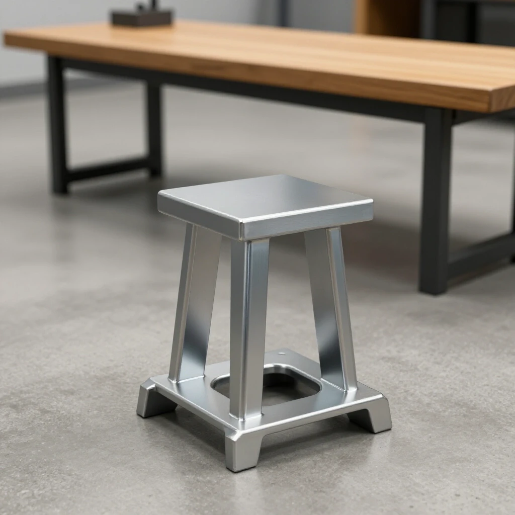
Throughout my 13 years as a prototype technician, I have learned that a truly stable machine base requires more than just thick steel. It requires a disciplined approach to weld sequencing layout and an understanding of how metal behaves when it reaches melting temperatures. Whether you are building a utility trailer or a precision support for a milling machine, the challenges remain the same: controlling heat warp and maintaining squareness. In this guide, I will break down the exact process I use to build rigid, vibration-resistant structures that stay true from the first cut to the final coat of paint.
Planning the Foundation: Material Selection and Load Considerations
Choosing the right steel profile and wall thickness ensures the machine stays stable during heavy cuts and reduces the vibration that ruins surface finishes.
When you start a custom fabrication project, the material you choose dictates your success. For a benchtop machine, you aren’t just holding up weight; you are resisting the harmonic vibrations of a spinning motor and the lateral forces of a cutting tool. I prefer using square structural tubing over angle iron because tubing offers much higher torsional rigidity. For most benchtop applications, 2-inch or 2.5-inch square tubing with a 3/16-inch or 1/4-inch wall thickness is the sweet spot. Anything thinner than 1/8-inch will likely flex under load and be more prone to blowing through during welding.
- Square Tubing: Best for resisting twisting and bending in all directions.
- C-Channel: Excellent for top perimeter frames where you need a flat mounting surface.
- Angle Iron: Useful for shelving or bracing, but lacks the rigidity needed for primary uprights.
Designing the Cut List and Calculating Kerf Allowances
Accurate layouts depend on accounting for the material lost during the cutting process to ensure final dimensions match the plan.
In my early days, I would mark a 24-inch line, cut it with an abrasive saw, and wonder why my part was 23-7/8 inches long. That missing 1/8-inch is the “kerf”—the width of the material turned into dust by your blade. If you have ten cuts in a project, and you don’t account for kerf, your final assembly could be over an inch off. For precision tool frames, I always use a “stop block” system on my saw to ensure every leg is identical. If your legs vary by even 1/16-inch, you will spend hours trying to shim the machine level later.
Metal Kerf Allowances by Cutter Type
| Cutting Tool | Typical Kerf Width | Best Use Case |
|---|---|---|
| Abrasive Chop Saw | 3/32″ to 1/8″ | Rough structural cuts |
| Cold Saw (Carbide) | 1/16″ to 3/32″ | Precision, cool-to-touch cuts |
| Portable Band Saw | 0.025″ to 0.035″ | On-the-fly adjustments |
| Plasma Cutter | 0.040″ to 0.060″ | Plate steel and gussets |
Squaring the Stock: Preparation for Accurate Fit-Up
Squaring the ends of your steel tubing ensures tight gaps, which are essential for strong, predictable welds and minimal distortion.
A common mistake is assuming the steel comes square from the mill. It rarely does. I always start by “truing” the ends of my stock. If your joints have gaps larger than 1/32-inch, the weld pool will have to fill that space, which creates more heat and more pull. I use a flap disc on a 4.5-inch grinder to remove the mill scale (the dark grey coating) at least one inch back from every joint. Welding through mill scale leads to porosity and weak joints, which is unacceptable for a structure that must remain rigid under vibration.
Building Workshop Jigs for Frame Alignment
Temporary fixtures and jigs hold parts in place during tacking to prevent the frame from pulling out of square as the metal cools.
You cannot hold a frame square by hand. Even the strongest grip will fail against the shrinking forces of a cooling weld. I recommend building a simple layout fixture on your welding table. This can be as simple as heavy steel blocks clamped to the table to create a 90-degree corner. When I built my first custom chassis, I used “squaring dogs”—small L-shaped pieces of scrap welded to the table—to lock my tubing in place. This ensures that when you apply heat, the metal has nowhere to move.
Essential Layout Tools for Metal Projects
- Machinist Squares: For checking internal corners with high precision.
- Fire-Resistant Clamps: Use copper-coated screws to prevent weld spatter from sticking.
- Magnetic Squares: Great for holding pieces temporarily, but never trust them for final alignment.
- Leveling Shims: Essential for setting up a flat plane on an uneven garage floor.
- Digital Protractor: To verify that cross-bracing angles are consistent.
Mastering Structural Tacking and Heat Control
Small, strategically placed welds hold the assembly together while allowing for minor adjustments before the final beads are laid.
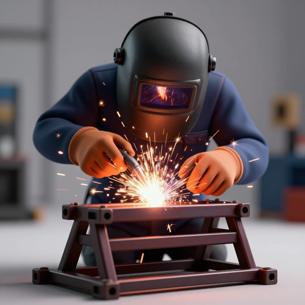
Tack welding is the most underrated skill in fabrication. A tack should be just large enough to hold the weight of the part, but small enough that you can “cold set” it with a hammer if you need to adjust the angle. I typically place tacks at the corners of the tubing. If I am welding a 2-inch joint, I’ll place four tacks—one on each side. Interestingly, as a tack cools, it will “pull” the metal toward the weld. I use this to my advantage; if a corner is slightly wide, I’ll place a heavy tack on the inside of the joint to pull it back into square.
Establishing a Weld Sequence to Combat Distortion
The order in which you weld joints determines how the metal pulls; a balanced sequence cancels out internal stresses.
This is where most DIY builders go wrong. They weld one entire joint from start to finish, then move to the next. By the time they reach the fourth corner, the frame is a trapezoid. To prevent this, you must use a balanced weld sequencing layout. Think of it like tightening the lug nuts on a car wheel. You want to jump from one corner to the opposite corner, allowing the heat to dissipate. By spreading the heat around the structure, you prevent any one area from becoming a “hinge” that pulls the rest of the frame out of alignment.
Weld Sequencing and Distortion Control
| Joint Type | Recommended Sequence | Expected Pull |
|---|---|---|
| T-Joint | Weld center out, alternate sides | 1-2 degrees angular |
| Corner Joint | Tack all 4 sides, weld opposite faces | Minimal if tacked heavily |
| Lap Joint | Short staggered beads (2″ on, 4″ off) | Significant longitudinal |
| Butt Joint | Back-step method (weld toward previous start) | Moderate shrinkage |
Why Weld Shrinkage Warps Square Structures
Understanding the physics of thermal expansion helps you predict where the metal will move before you even pull the trigger.
When you weld, you are heating steel to over 2,500 degrees Fahrenheit. The metal expands as it gets hot, but as it cools, it shrinks significantly more than it expanded. This is known as “angular distortion.” If you weld only on the top of a horizontal beam, the beam will “smile” (curve upward) as the weld cools. To combat this, I often “pre-set” my joints. If I know a weld will pull a leg inward by 1/16-inch, I will clamp the leg 1/16-inch “out” of square before welding. When the weld cools, it pulls the leg into the perfect 90-degree position.
Integrating Cross-Bracing for Maximum Rigidity
Diagonal members triangulate the frame, preventing swaying and lateral movement when the machine is running.
A square frame is inherently weak against lateral (side-to-side) forces. If you push on the top of a simple four-legged stand, it will eventually “parallelogram” and collapse. To prevent this in my workshop fixtures, I always add diagonal bracing. You don’t need to brace every side, but having at least two sides with an “X” or “K” pattern will transform a wobbly stand into a rock-solid pedestal. I prefer using 1-inch flat bar or smaller square tubing for these braces to keep the weight down while maximizing the “triangulation” effect.
Leveling and Finishing the Support Structure
Final adjustments ensure the machine sits flat, which is critical for maintaining accuracy over time and preventing frame stress.
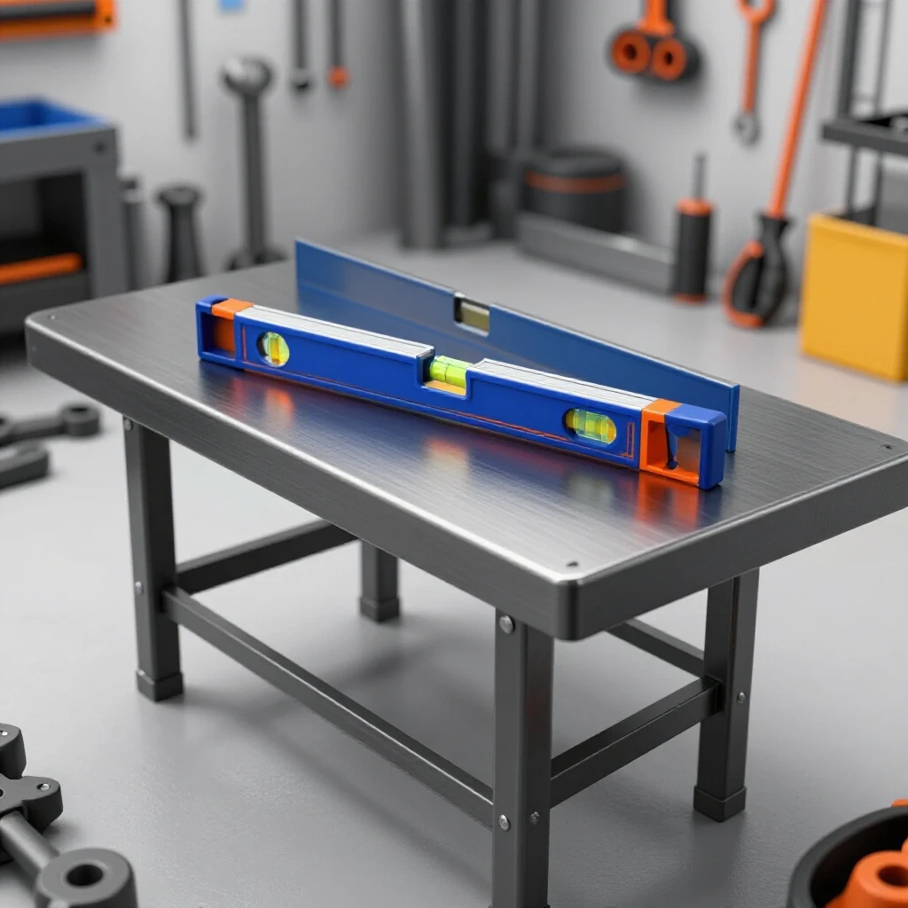
No garage floor is perfectly flat. If you bolt a rigid steel stand to an uneven floor, you will twist the frame, which can actually warp the bed of the machine you put on top of it. I always integrate heavy-duty leveling feet. I weld a threaded nut (usually 1/2-inch or 5/8-inch) into the bottom of each leg. This allows me to use a precision level to ensure the top surface is perfectly horizontal. Once leveled, I use a second nut as a “jam nut” to lock the foot in place so vibration doesn’t cause it to drift.
Actionable Build Log: Step-by-Step Execution
Following a structured workflow reduces the “analysis paralysis” that often hits mid-project.
- Cut All Material: Use a stop block for identical lengths. Label each piece with a paint marker.
- Prep Joints: Grind all mating surfaces to shiny metal. Remove internal burrs from tubing.
- Layout the Top: Clamp the top perimeter to your welding table. Check diagonals (they must be equal).
- Tack the Perimeter: Use small 1/8-inch tacks. Re-check diagonals after each tack.
- Attach Legs: Use a machinist square to hold legs at 90 degrees. Tack on opposite sides.
- Add Bracing: Cut diagonals to fit tightly. Tack them in place while the frame is still clamped.
- Final Weld-Out: Follow the “star pattern” sequence. Do not weld more than 3 inches at a time in one spot.
- Cooling: Let the frame air cool. Never quench a weld with water, as it makes the steel brittle.
- Grinding: Clean up only the welds that interfere with mounting. Leaving the “stack of dimes” adds strength.
- Leveling: Install threaded feet and move the stand to its final location before leveling.
Correcting Distortion After the Fact
Even with the best planning, metal sometimes has a mind of its own and requires post-weld correction.
If you find that your stand has a slight wobble or a leg is 1/8-inch out of square, don’t panic. You can use “heat shrinking” to pull it back. By heating a small spot on the opposite side of the warp with an oxy-acetylene torch and then cooling it quickly with a wet rag, you can force the metal to shrink and pull the structure back into alignment. This is a technique I used frequently when building custom chassis where tolerances were within 0.030 inches. It takes practice, but it is a powerful tool in your fabrication arsenal.
Frequently Asked Questions
How do I stop my frame from pulling out of square during welding? The best metal warping solutions involve a combination of heavy clamping, large tacks, and a balanced weld sequence. Never weld one side completely before moving to the next. Always work in small increments on opposite sides of the structure to balance the cooling forces.
What is the best weld sequence for a four-sided frame? I recommend welding the “inside” corners first, then the “outside” corners, moving in a diagonal pattern (Front-Left, Back-Right, Front-Right, Back-Left). This distributes the heat evenly across the entire footprint.
How much gap should I leave between pieces for a good weld? For structural tubing, a “tight fit” (less than 1/32-inch) is ideal for MIG welding. If you are TIG welding, you want zero gap. Large gaps require more filler metal, which creates more heat and more distortion.
Can I use a wood top on a steel stand for a mill? While wood is great for workbenches, it is not ideal for precision machine stands. Wood expands and contracts with humidity, which can throw off the level of your machine. A thick steel plate or a reinforced steel frame is much better for maintaining accuracy.
What wall thickness is best for a 500lb machine? For a load of that size, I suggest 3/16-inch wall thickness. It provides enough “meat” for deep weld penetration and is heavy enough to dampen the vibrations of the machine.
Do I need to weld all the way around every joint? For a machine stand, yes. Full-perimeter welds prevent the joints from flexing under the constant vibration of the motor. However, you should still use a sequence to avoid overheating the joint in one pass.
How do I calculate the height of my stand? Measure from your elbow to the floor while standing comfortably. Subtract the height of the machine’s table from that measurement. This ensures the machine’s handles are at a comfortable working height, reducing fatigue during long projects.
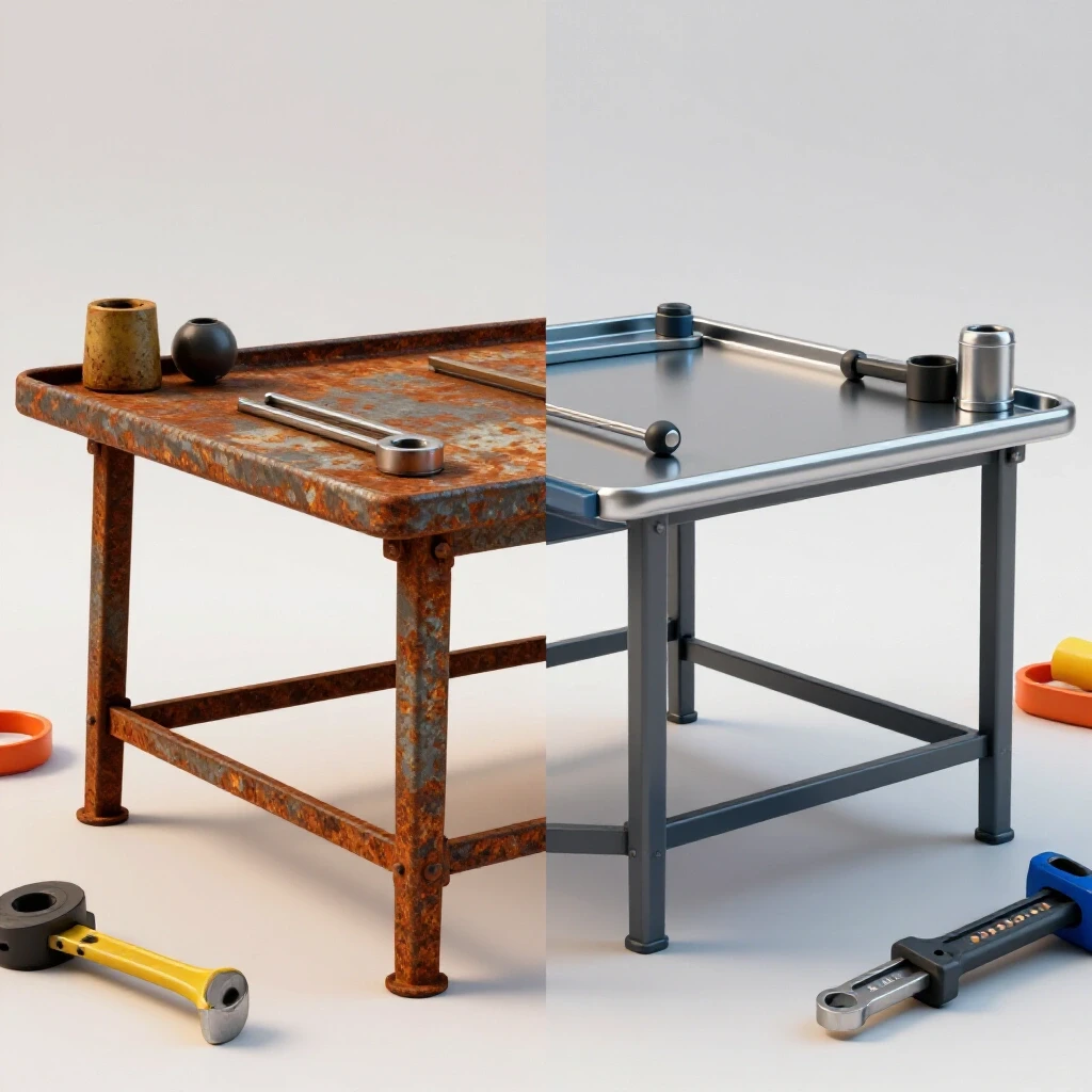
Should I paint or powder coat my stand? If you are in a humid garage, paint is a must to prevent rust. I prefer a high-quality “hammered” finish spray paint because it hides minor welding imperfections and is easy to touch up if you scratch it later.
How do I ensure the top is flat if I don’t have a professional fixture table? Use a “poor man’s surface plate.” Find the flattest part of your concrete floor or use two parallel lengths of heavy C-channel on a workbench. Use a long straight edge and shims to create a level plane before you start tacking your top frame.
What is the most common mistake in custom fabrication projects? Rushing the fit-up. Most builders spend 10% of their time on layout and 90% on welding. It should be the opposite. If your pieces fit together perfectly with no gaps before you start the welder, the project will go smoothly. If you are “filling holes” with weld, you are asking for warping.
Building a rigid support structure is a rite of passage for any serious DIY fabricator. It forces you to respect the material and think three steps ahead of the heat. By focusing on accurate cuts, disciplined tacking, and a smart welding sequence, you can build workshop fixtures that are just as precise as the tools they support. The key is patience; let the metal cool, check your square often, and never underestimate the power of a good clamp. Next time you start a project, remember that the time spent on the layout is the best insurance against a warped finished product.
(This article was written by one of our staff writers, Robert Kline. Visit our Meet the Team page to learn more about the author and their expertise.)