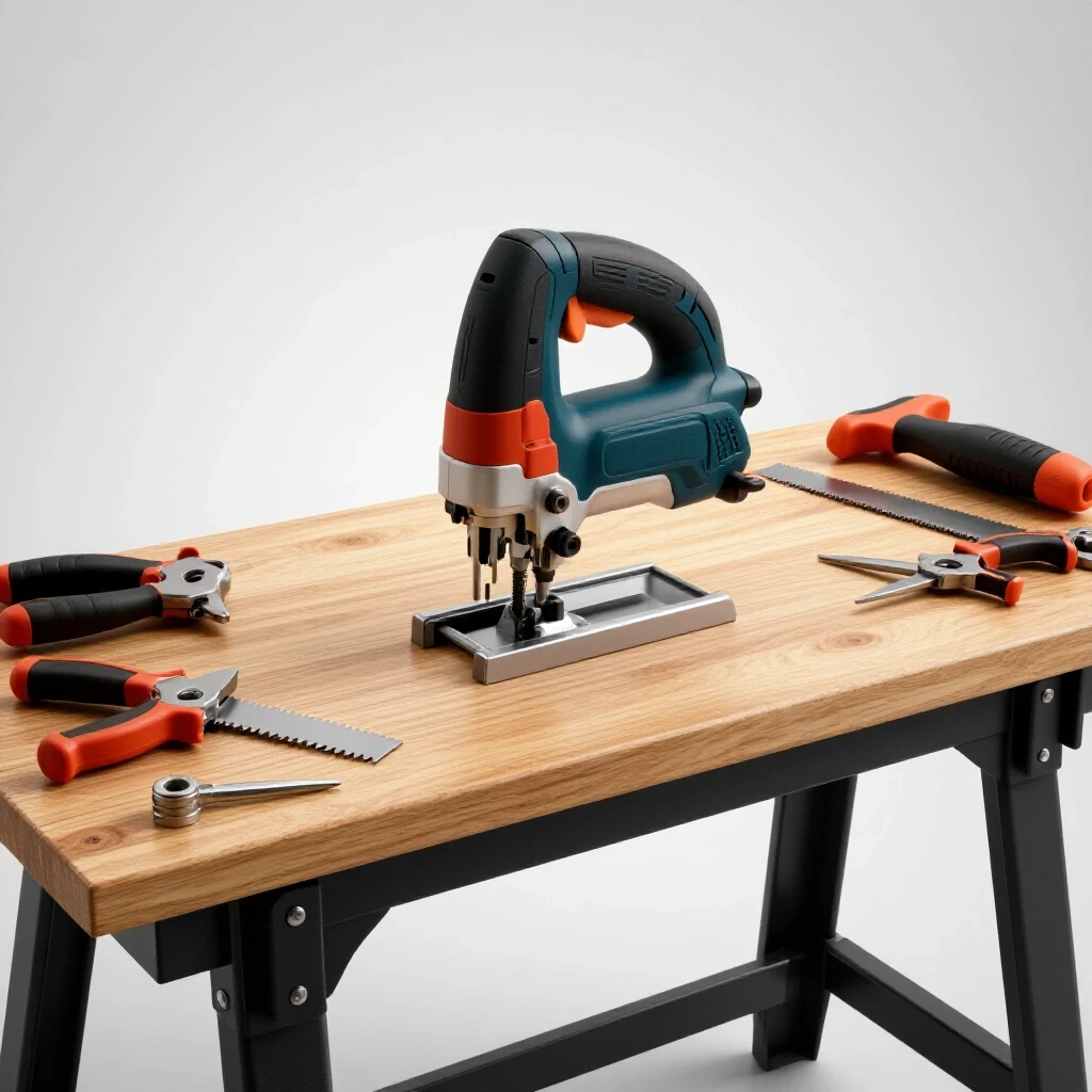
How to Build a Rolling Metal Workbench With Casters (DIY Plan)
I remember the first time I tried to build a heavy-duty shop table. I had measured everything three times and cut my square tubing with what I thought was surgical precision. But as soon as I finished the final corner bead and the metal cooled, I noticed the legs were pulling inward like a closing pair of scissors. The top was no longer flat, and the whole frame rocked on the floor. It was a gut-punch. That project taught me that steel is a living thing when you introduce heat. It expands, it contracts, and if you don’t have a plan to manage those forces, it will fight you every step of the way.
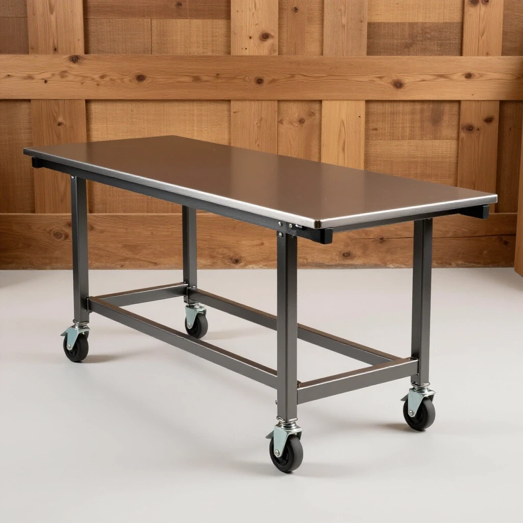
Thirteen years in prototype shops and custom chassis fabrication have taught me that success isn’t just about a steady hand with a MIG gun. It is about the preparation you do before the hood even drops. For those of us building in a garage or a small shop, the goal is a tool that stays flat, square, and mobile under heavy loads. Whether you are mounting a vise or using the surface for layout work, your base needs to be a rock-solid foundation. We are going to walk through the process of constructing a mobile steel station, focusing on the technical hurdles like heat management and layout accuracy that often trip up even seasoned DIYers.
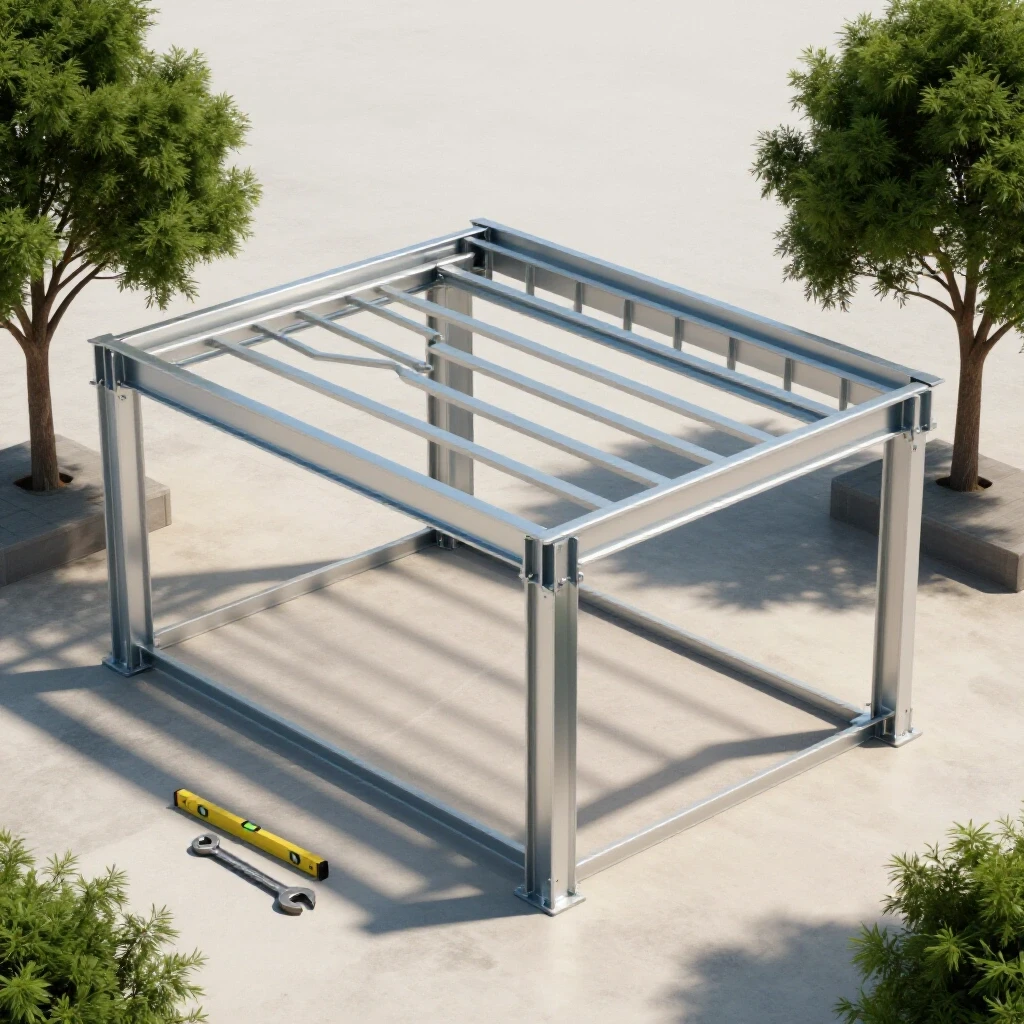
Designing Your Framework and Planning Material Procurement
Structural design for shop equipment involves balancing weight, cost, and the specific forces the frame will encounter during use. This stage involves translating your concept into a detailed cut list while accounting for material thickness and the width of your saw blade. Proper planning prevents the common “oops, I’m an inch short” scenario during assembly.
When I plan custom fabrication projects, I start with the material choice. For a standard mobile unit, 2-inch by 2-inch square tubing with a 1/8-inch wall thickness is the sweet spot. It is heavy enough to handle several hundred pounds but light enough to cut with a standard abrasive saw. If you go too thin, like 16-gauge, you risk burning through during welding and losing structural rigidity.
Your cut list must account for how the joints overlap. If you want a frame that is exactly 48 inches wide, and you are using 2-inch tubing, your cross-members need to be 44 inches long if they sit between the main rails. This is a common place where errors creep in. I always draw a “top-down” view of the frame to visualize where each piece of steel ends. This helps me calculate the exact linear footage needed, which prevents wasted trips to the local steel yard.
- Material Choice: 2×2 Square Tubing (1/8-inch wall).
- Top Surface: 1/4-inch or 3/8-inch A36 steel plate.
- Caster Capacity: Minimum 300 lbs per wheel for a 1,200 lb total capacity.
- Tolerance Goal: +/- 1/16-inch across the entire frame.
Managing Kerf and Accuracy During the Cutting Phase
Accuracy begins at the saw, where even a slight 1-degree error over a 4-foot span can ruin your project’s squareness. Understanding how tool kerf impacts final dimensions ensures your parts fit together without gaps. Kerf is the width of the material removed by the cutting blade, and ignoring it is the fastest way to end up with a project that is too short.
If you are using a standard chop saw with an abrasive blade, your kerf is likely around 3/32 of an inch. If you make ten cuts and don’t account for that, you have lost nearly an inch of material. I always mark my line and then ensure the blade falls on the “waste” side of that line. This keeps the finished piece at the exact dimension I intended.
After cutting, every piece needs to be deburred. The small “ears” of metal left by the saw prevent the pieces from sitting flush against each other. This creates a gap that the weld will try to pull closed, leading to distortion. I use a flap disc on a 4.5-inch grinder to clean the ends until they are bright and flat. This also removes the mill scale (the dark gray coating on new steel), which is essential for a clean, strong weld.
| Cutter Type | Typical Kerf Width | Dimensional Accuracy |
|---|---|---|
| Abrasive Chop Saw | 3/32″ to 1/8″ | +/- 1/16″ |
| Cold Saw | 1/16″ | +/- 1/32″ |
| Horizontal Bandsaw | 0.035″ to 0.050″ | +/- 1/64″ |
| Plasma Cutter (Handheld) | 1/16″ to 1/8″ | +/- 1/8″ |
Building Layout Jigs and Fixturing for Structural Integrity
Jigs are temporary structures used to hold metal pieces in the correct orientation during the welding process. They act as a physical restraint against the powerful forces of thermal contraction that occur as welds cool. Without fixturing, the heat from your torch will pull your 90-degree corners into acute angles.
In my shop, I don’t always have a professional 5,000-dollar welding table. Instead, I use workshop jigs and fixtures made from scraps of angle iron and heavy C-clamps. To keep a frame square, I often clamp the perimeter pieces to a flat concrete floor or a sacrificial wooden bench. If the floor is uneven, I use shims and a long level to ensure the four corners are on the same plane.
One trick I use is the “3-4-5 rule” to check squareness. Measure 3 feet on one rail and 4 feet on the perpendicular rail. If the diagonal between those two points is exactly 5 feet, your corner is square. For a smaller frame, you can use 15, 20, and 25 inches. I never trust a speed square alone for a large frame because a tiny error at the corner multiplies over the length of the tubing.
- Step 1: Lay out the perimeter on a flat surface.
- Step 2: Clamp the corners using 90-degree magnets or dedicated corner clamps.
- Step 3: Measure the diagonals of the entire rectangle. They must be identical.
- Step 4: Secure the frame to the work surface to prevent it from lifting during tacking.
Understanding Weld Sequencing and Thermal Distortion Control
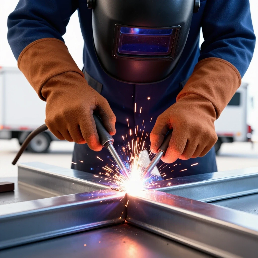
Weld sequencing is the strategic order in which you apply heat to a joint to balance out the pulling forces of cooling metal. By alternating sides and positions, you use one weld’s shrinkage to counteract another’s. This is the most critical phase of any custom fabrication project.
When steel is heated to a molten state and then cools, it shrinks. This shrinkage exerts thousands of pounds of force. If you weld the entire outside of a joint first, it will pull the leg outward. To combat this, I start with small, strong tack welds. A tack weld should be about 1/4 inch long and placed at the center of each side of the joint.
Once the frame is tacked and I have re-verified the squareness, I follow a “staggered” sequence. I never finish one joint completely before moving to the next. Instead, I weld the top of corner A, then the top of corner C (the diagonal opposite), then B, then D. This distributes the heat evenly across the structure. This metal warping solution keeps the frame from “diamonding” or twisting.
| Weld Sequence Step | Location | Purpose |
|---|---|---|
| 1. Initial Tacks | All Corners (Inside) | Holds basic shape and allows for minor adjustments. |
| 2. Secondary Tacks | All Corners (Outside) | Locks the 90-degree angle before full beads. |
| 3. Structural Beads | Top Flats (Diagonal Pattern) | Provides primary strength while balancing heat. |
| 4. Vertical Beads | Outside Corners | Seals the joint and adds structural rigidity. |
| 5. Final Beads | Inside Corners | Completes the joint; usually causes the most pull. |
Integrating Heavy-Duty Mobility and Load Distribution
Adding wheels to a heavy steel frame requires reinforcing the mounting points to prevent the metal from buckling under stress. Proper caster selection ensures the table remains stable and easy to move across uneven shop floors. A common mistake is welding the casters directly to the thin wall of the tubing, which can lead to the metal tearing over time.
I prefer to weld 1/4-inch thick steel plates to the bottom of the legs first. These plates should be slightly larger than the mounting bracket of the caster. This distributes the weight of the table across a larger surface area of the tubing. I then drill and tap the plates or use through-bolts to secure the casters. Welding casters directly is risky because the heat can damage the internal bearings or the rubber wheel.
When choosing casters, look for “total lock” versions. These lock both the wheel rotation and the swivel mechanism. A table that swivels while you are trying to saw a piece of wood is a safety hazard. I also recommend using casters with polyurethane wheels rather than hard plastic. Polyurethane handles small shop debris like metal chips much better and won’t flat-spot if the table sits in one place for a month.
- Cut four 4×4-inch plates from 1/4-inch flat bar.
- Center the plates on the bottom of the legs and tack weld.
- Weld the plates using a “stitch” pattern to avoid overheating the leg.
- Drill holes for the caster bolts after the metal has cooled.
- Install casters and ensure all four touch the ground simultaneously.
Correcting Warpage and Final Post-Weld Alignment
Even with the best planning, some distortion is inevitable due to the nature of steel and heat. Post-weld alignment involves using mechanical force or strategic heat application to bring the structure back into tolerance. If you find a leg has pulled 1/8-inch out of square, don’t panic.
One method I use is “flame straightening.” By applying heat to the side of the tube opposite the warp, you can cause that side to shrink as it cools, pulling the part back into alignment. However, this takes practice. A more beginner-friendly approach is using a heavy-duty bar clamp or a bottle jack. If a leg is leaning in, I place a jack between the legs and apply just enough pressure to push it slightly past “square,” then release it.
Finally, check the top surface. If the frame has a slight twist, you can often correct it by how you mount the top plate. For a 1/4-inch steel top, I use a “plug weld” technique. I drill holes through the top plate into the frame below, then fill those holes with weld. This pulls the plate tight against the frame. Start in the center and work your way out to the edges to ensure the top stays as flat as possible.
- Check Diagonals: Ensure they are within 1/16-inch.
- Check Flatness: Use a 4-foot level across the top rails.
- Check Leg Plumb: Ensure legs are 90 degrees to the floor.
- Grind Welds: Only grind the welds that interfere with the top plate; leave the corner beads for strength.
Summary of Technical Benchmarks
Building a mobile shop station is a lesson in physics. Every action has a reaction in the form of metal movement. By following a structured approach, you can manage these reactions and produce a tool that will last for decades.
- Tack Spacing: Every 2 inches for long seams, or one per side on tubing.
- Heat Control: If the metal is glowing bright red for more than a second, you are moving too slow or using too much voltage.
- Clamp Density: One clamp every 12 inches when securing a frame to a flat surface.
- Dimensional Tolerance: Aim for +/- 1/16-inch; anything more will be visible to the eye.
The most important thing to remember is that fabrication is a process of constant measurement and adjustment. If you catch a mistake during the tacking phase, it takes ten seconds with a grinder to fix. If you wait until the project is fully welded, it takes an hour with a reciprocating saw. Take your time, plan your sequence, and respect the heat.
Frequently Asked Questions
What is the best way to ensure the frame is square before welding? The most reliable method is measuring the diagonals. In a rectangular frame, if the distance from the top-left corner to the bottom-right corner matches the distance from the top-right to the bottom-left, the frame is square. I always do this after tacking but before final welding.
Should I use MIG or TIG for a workshop table project? MIG (Metal Inert Gas) is generally preferred for this type of work because it is faster and puts less total heat into the metal compared to TIG (Tungsten Inert Gas). Less heat means less warping. MIG is also more forgiving on mill scale, though you should still clean your joints.
How do I stop the casters from wobbling on an uneven floor? Even a perfectly built frame will wobble if your floor isn’t flat. I recommend using “leveling casters” or adding a threaded stud to one corner of the frame. This allows you to adjust the height of one wheel by a fraction of an inch to eliminate the rock.
Is it better to weld or bolt the top surface? Welding the top provides more structural rigidity but makes it permanent. If you think you might want to replace the top later (e.g., switching from wood to steel), I suggest welding tabs to the inside of the frame and bolting the top from underneath.
What thickness of steel is best for the top? For most DIYers, 1/4-inch steel plate is the gold standard. It is heavy enough to weld on without warping easily, but not so heavy that the table becomes impossible to move. If you plan on doing a lot of heavy hammering, 3/8-inch is a better choice.
How do I prevent the legs from pulling inward when I weld the bottom shelf? The bottom shelf acts as a brace. To keep the legs from pulling, tack the shelf in place while the legs are clamped to a known square reference. Use the same diagonal weld sequencing on the shelf as you did on the main frame.
Do I really need to remove the mill scale? Yes. Mill scale is an oxide layer that has a higher melting point than the steel underneath. If you weld over it, you risk “cold lap,” where the weld sits on top of the metal rather than penetrating it. It also causes the arc to sputter and creates more spatter.
How big should my tack welds be? For 1/8-inch tubing, a tack should be about the size of a pencil eraser. It needs to be strong enough to hold the weight of the part if you bump it, but small enough that you can easily cut it with a thin zip-disc if you need to make an adjustment.
Can I build this out of angle iron instead of square tubing? You can, but angle iron is much more prone to twisting. Square tubing has much higher torsional rigidity (resistance to twisting). If you use angle iron, you will need to add more gussets and cross-braces to achieve the same strength.
What is the “heat-affected zone” (HAZ) and why does it matter? The HAZ is the area around the weld that didn’t melt but was changed by the heat. This area is often where the metal is most likely to warp or become brittle. By using a staggered weld sequence, you keep the HAZ from becoming too large in any one area.
(This article was written by one of our staff writers, Robert Kline. Visit our Meet the Team page to learn more about the author and their expertise.)