How to Build a Rolling Storage Cart for Cutting Oils (Plan)
I’ve spent the last 13 years in fabrication shops, and if there is one thing I have learned, it is that steel has a mind of its own. I remember early in my career, I was building a simple frame for a mobile shop unit. I had every piece cut to the exact sixteenth of an inch. I clamped it down, felt confident, and ran my beads. When I unclamped it, the entire frame had pulled into a diamond shape, off by nearly half an inch. It was a humbling lesson in how heat moves metal.
That frustration is something every DIY builder faces. You put in the hours of planning and cutting, only to watch the heat from your welder twist your hard work into something unusable. In this guide, I’m going to walk you through the process of building a mobile organizer for your shop lubricants and fluids. We will focus on the technical side of fabrication: managing heat warp, ensuring square layouts, and sequencing your welds so the final product stays true to your original design.
Mastering the Cut List and Material Allowances for Shop Organizers
Planning a fabrication project starts with a detailed cut list that accounts for the physical realities of the tools you are using. A cut list is a roadmap that prevents wasted material and ensures that every component of your mobile fluid station fits together without forced gaps or overlaps.
When you start your layout, you have to account for “kerf.” Kerf is the width of the material removed by the cutting tool. If you use a standard abrasive chop saw, your kerf might be 1/8th of an inch. If you ignore this, and you have ten cuts to make, your final piece could be over an inch short. I always mark my lines and then cut on the “waste side” of the line to maintain my dimensional tolerances. For a project like a lubricant cart, staying within a +/- 1/16th inch tolerance is my personal benchmark for a professional result.
Understanding Kerf and Blade Thickness
The thickness of your cutting blade dictates how much material disappears during the process, which directly impacts the final dimensions of your frame. If you are using a bandsaw, your kerf is much thinner than a gas-powered saw, meaning you have more room for error, but precision still requires a steady hand and a sharp blade.
- Abrasive Saws: Typically 3/32″ to 1/8″ kerf. These generate high heat and can leave a burr that must be ground off before welding.
- Cold Saws/Bandsaws: Typically 0.035″ to 0.060″ kerf. These provide much cleaner cuts and require less post-cut cleanup.
- Plasma Cutting: Can vary from 0.040″ to 0.080″ depending on the tip size and travel speed.
Metal Kerf Allowances by Cutter Type
| Cutting Tool | Average Kerf Width | Precision Level | Best Use Case |
|---|---|---|---|
| Abrasive Chop Saw | 0.125″ (1/8″) | Low | Rough framing and thick angle iron |
| Portable Bandsaw | 0.035″ – 0.042″ | High | Precision tubing and small profiles |
| Angle Grinder (Slicing Disk) | 0.040″ – 0.062″ | Medium | Quick field cuts and notched corners |
| Plasma Cutter | 0.050″ – 0.090″ | Medium | Sheet metal and irregular shapes |
Precision Layout Techniques to Ensure a Square Foundation
A square foundation is the difference between a cart that rolls straight and one that wobbles throughout its life. Using layout tools properly ensures the frame starts true before any heat is applied, providing a reliable base for the rest of your custom fabrication project.
In my shop, I don’t just trust a speed square. I use the 3-4-5 rule for larger frames to verify squareness across the diagonals. If the distance from corner to corner isn’t identical, the frame is a trapezoid, not a rectangle. I also use layout dye or a fine-point scribe. A thick soapstone mark can be 1/16th of an inch wide on its own, which introduces too much variability. If you can’t see a crisp line, you can’t make a crisp cut.
The Importance of Deburring and Surface Prep
Before you even think about tacking your metal layout, every cut end must be deburred. A burr is a small ridge of displaced metal left by the cutting tool. If a burr is left on the end of an angle iron leg, it will prevent the joint from sitting flush. This creates an uneven gap that will pull the joint out of square as the weld cools and shrinks.
- Use a flap disc or a file to remove the sharp edges from every cut.
- Clean the weld zone (at least one inch back from the joint) to shiny silver metal.
- Remove all mill scale, which is the dark flaky coating on hot-rolled steel, to ensure a stable arc and deep penetration.
Utilizing Workshop Jigs and Fixtures to Prevent Movement
Fixtures are temporary structures or clamps that hold your workpiece in place during the welding process, fighting the natural tendency of metal to move as it heats. Without physical restraint, the cooling weld metal will act like a powerful spring, pulling your vertical legs inward.
I often build simple workshop jigs using scrap angle iron or heavy C-clamps. For a mobile storage unit, I might clamp the base frame to my heavy welding table. This acts as a “heat sink” and a mechanical restraint. If you don’t have a dedicated welding table, you can use a flat concrete floor, but be careful of the moisture in the concrete popping under the heat of the arc.
Strategic Clamping for Angular Alignment
When you clamp a joint, you are fighting angular weld shrinkage. This is the phenomenon where the top of a weld cools faster than the bottom, pulling the two pieces of metal toward the bead. By using heavy-duty F-clamps or locking pliers, you can keep the parts at a 90-degree angle while the tack welds solidify.
- Corner Clamps: Essential for holding 90-degree angles in square tubing or angle iron.
- Strongback Jigs: A piece of heavy scrap metal clamped across a joint to prevent it from bowing upward.
- Tack Spacing: Place tacks at the corners first, then check for square before adding more.
Fixturing Span Recommendations for Frame Stability
| Material Thickness | Maximum Distance Between Clamps | Suggested Tack Weld Size |
|---|---|---|
| 1/8″ (11 gauge) | 12 inches | 1/8″ diameter |
| 3/16″ (7 gauge) | 18 inches | 3/16″ diameter |
| 1/4″ and up | 24 inches | 1/4″ diameter |
Strategic Weld Sequencing to Control Thermal Distortion
Weld sequencing is the specific order in which you apply heat to a joint to balance the internal stresses that cause metal to pull or warp. If you weld all the way around one joint before moving to the next, you will almost certainly end up with a twisted frame.
The goal is to distribute the heat evenly. I prefer to “jump around” the project. I’ll weld the front-left corner, then move to the back-right corner. This allows the first joint to cool slightly while the second joint pulls in the opposite direction, effectively canceling out some of the distortion. This is a critical step in any custom fabrication project where dimensional accuracy is the priority.
The Physics of Weld Shrinkage
When steel is heated to a molten state, it expands. As it cools back to a solid, it shrinks. Because the weld bead is attached to the cooler base metal, it cannot shrink freely. This creates internal tension. If the tension is stronger than the stiffness of your frame, the frame will bend. By understanding this “pull,” you can actually pre-set your joints a few degrees “out” of square so that the weld pulls them into the correct position.
- Tack Weld Everything: Never fully weld a joint until the entire structure is tacked together and verified for squareness.
- Opposing Beads: If you weld the inside of a corner, follow it by welding the outside of the same corner to balance the pull.
- Short Runs: Instead of one long continuous bead, use several shorter beads to minimize the total heat input in one area.
Weld Sequencing and Distortion Control Framework
| Joint Type | Sequence Strategy | Result |
|---|---|---|
| T-Joint | Weld side A, then flip and weld side B immediately. | Minimizes the “leaning” of the vertical member. |
| Butt Joint | Start in the center and weld outward to the edges. | Prevents the plates from “zippering” or overlapping. |
| Corner Frame | Weld diagonal corners in a “star” pattern. | Keeps the overall frame from becoming a diamond. |
| Lap Joint | Use intermittent “stitch” welds rather than a solid bead. | Reduces long-term warping in sheet metal trays. |
Integrating Shelving and Drip Trays into the Frame
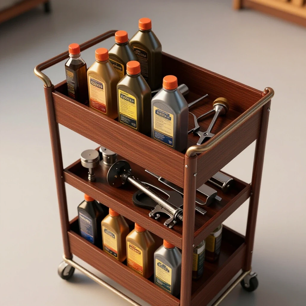
Adding shelves and trays to your mobile unit requires careful management of thin materials to prevent oil-canning. Oil-canning is when sheet metal pops in and out because the perimeter has been welded and shrunk, while the center of the sheet remains the same size.
For a lubricant organizer, I like to use 14 or 16-gauge sheet metal for the shelves. To keep these flat, I avoid continuous welds. Instead, I use 1-inch stitch welds spaced about 6 inches apart. This provides plenty of strength to hold heavy jugs of oil but keeps the heat low enough that the shelves don’t look like a topographical map when I’m finished.
Fabricating Secure Holders and Dividers
A functional cart needs to keep containers from sliding around. I often use small strips of flat bar or light angle iron to create “corrals” for specific bottle sizes.
- Layout Tip: Measure your largest containers and add 1/4 inch of clearance. This accounts for variations in bottle shapes and allows you to clean the trays easily.
- Drainage: If you are building drip trays, consider a slight pitch (about 1/8 inch over a foot) toward a corner so you can wipe out spilled oil easily.
- Edge Protection: Use a deburring tool or a small radius on all sheet metal edges. Sharp edges on a shop cart are a recipe for cut knuckles.
Final Assembly and Mobility Considerations
Mounting casters and finishing the build ensures the unit is functional and durable enough to handle the daily movement of a busy shop. The way you attach your casters can actually introduce a final bit of warp if you aren’t careful with your heat.
I prefer to weld caster mounting plates to the bottom of the legs rather than welding the casters directly. This allows you to bolt the casters on, making them easy to replace if a wheel fails or gets flat spots from sitting too long. When welding these plates, I use the same sequencing rules: tack all four corners, then weld in a cross pattern to keep the plate flat so the caster sits level.
Selecting and Installing Casters
A mobile cart is only as good as its wheels. For a shop environment, I always look for polyurethane wheels with ball-bearing swivels. They roll over metal shavings and small debris much better than hard plastic or rubber.
- Four-Wheel Steer vs. Two-Wheel Steer: Using four swivel casters makes the cart highly maneuverable in tight spaces, but harder to push in a straight line over long distances.
- Locking Mechanisms: At least two of your casters should have total-lock brakes that stop both the wheel rotation and the swivel.
- Mounting Height: Ensure your ground clearance is at least 2 inches to avoid getting hung up on shop door thresholds or uneven concrete.
Actionable Framework for a Successful Build
To keep your project on track, I recommend using a simple checklist. This keeps you from rushing into a weld before the layout is truly ready.
- Verify Cut List: Double-check all lengths against your blueprint.
- Prep Surfaces: Grind all joints to clean metal and deburr all edges.
- Initial Layout: Lay the frame out on a flat surface and check diagonals.
- Primary Tacking: Place 1/8″ tacks at every corner.
- The “Square Check”: Re-measure diagonals. If they are off, use a dead-blow hammer to nudge the frame back into square.
- Final Welding: Follow your predetermined sequence, jumping between corners to manage heat.
- Post-Weld Cleanup: Use a wire wheel or flap disc to remove spatter and prepare for paint.
Post-Weld Alignment Log
If you find that your frame has warped despite your best efforts, don’t panic. You can often correct it with “heat shrinking” or mechanical force.
- Mechanical Correction: Use a long bar or a heavy-duty clamp to pull the frame back into square, then “stress relieve” the joints by lightly tapping them with a hammer.
- Heat Shrinking: Apply a small amount of heat with a torch to the side of the member that is too long. As it cools, it will shrink and pull the part back toward center.
- Documentation: Note which joints pulled the most. This data will help you adjust your weld sequencing on your next custom fabrication project.
Summary of Key Fabrication Metrics
- Dimensional Tolerance: Target +/- 1/16th inch for all frame components.
- Squareness Check: Diagonals must be within 1/8th inch of each other for a standard 24″ x 36″ frame.
- Tack Size: Approximately 1 to 1.5 times the thickness of the material.
- Heat Control: If the metal is glowing dull red more than 1/2 inch away from the weld, you are moving too slowly or using too much amperage.
By following these steps, you aren’t just building a place to store your oils; you are practicing the fundamental skills of a professional fabricator. You are learning to anticipate how metal reacts to heat and how to use mechanical force to keep your projects straight. It takes patience, but the result is a shop tool that looks as good as it functions.
FAQ: Common Challenges in Custom Shop Fabrications
How do I prevent my frame from “walking” while I am tacking it? Metal often moves the moment the arc strikes. To prevent “walking,” use a heavy clamp directly over the joint. If you are working on a table, tack the workpiece to the table itself in a few spots. These “bridge tacks” can be easily ground off later but will hold the piece perfectly still during the initial assembly.
What is the best way to fix a frame that is out of square after welding? If the frame is off by more than 1/4 inch, you may need to cut a few welds and re-tack. However, for minor deviations, you can use a “port-a-power” or a heavy-duty ratchet strap to pull the frame into square and then add a gusset or a shelf to lock it into the new, correct position.
Why do my welds look good but the joint still cracks? This is often due to “hydrogen embrittlement” or poor penetration. If you are welding over mill scale or oil, the weld will be weak. Always grind your joints to shiny metal. Also, ensure you aren’t cooling the weld too fast with water, as this can make the steel brittle and prone to cracking under the stress of shrinkage.
How many tacks are enough for a 2-foot section of angle iron? For a standard shop cart, I recommend a tack every 6 to 8 inches. This provides enough mechanical strength to hold the piece during welding while still allowing some flexibility if you need to make minor adjustments with a hammer.
Can I use a magnet to hold my parts square? Magnets are great for a “third hand,” but they are not a substitute for clamps. The magnetic field can also cause “arc blow,” where the welding arc is deflected away from the joint. Use magnets for the initial layout, but switch to mechanical clamps before you start welding.
What thickness of steel is best for a beginner’s cart project? I recommend 1/8-inch (11 gauge) thick angle iron or square tubing. It is thick enough that you won’t easily blow holes through it with a welder, but light enough to cut and move easily. It also handles heat much better than thinner 16-gauge materials.
How do I calculate the diagonal measurement for a square frame? Use the Pythagorean theorem ($a^2 + b^2 = c^2$). If your cart is 20 inches by 30 inches, square both numbers ($400 + 900 = 1300$) and take the square root. The diagonal should be approximately 36.05 inches. If both diagonals match that number, your frame is square.
Should I weld the inside or the outside of the corner first? Always tack the corners first. This sequence tends to pull the metal in a way that keeps the vertical legs from tilting inward.
How do I stop sheet metal shelves from rattling? If your shelves are just sitting in a frame, they will vibrate and make noise. Use a few small “stitch” welds or even a bead of silicone caulk between the shelf and the frame before bolting it down. This dampens the vibration and makes the cart feel much more solid.
What is the most common mistake in layout? The most common mistake is measuring from different ends of the material. Always establish a “datum” or a “factory edge” and take all your measurements from that single point. This prevents “stacking errors,” where small mistakes in each measurement add up to a large error at the end of the part.
(This article was written by one of our staff writers, Robert Kline. Visit our Meet the Team page to learn more about the author and their expertise.)