How to Build Adjustable Cargo Stops for Trailers (DIY Guide)
I remember standing in my driveway a few years ago, staring at a length of square tubing that had turned into a banana. I was building a set of sliding brackets for my utility trailer, and I thought I could just wing the welding sequence. I clamped the pieces down, ran a hot bead across the top, and watched in real-time as the heat pulled the metal out of alignment. By the time it cooled, the sliding sleeve was jammed solid against the inner rail. It was a humbling reminder that in custom fabrication projects, heat is either your tool or your enemy.
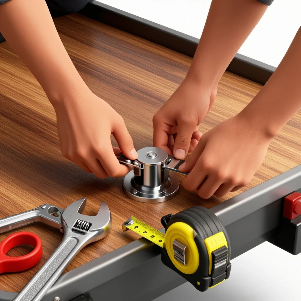
As a former prototype technician, I’ve spent over a decade learning that a successful build isn’t just about the final weld. It is about the math you do before the saw starts and the fixtures you build to keep things straight. When you are constructing load-securing hardware for a trailer, precision is the difference between a bracket that slides like silk and one that requires a sledgehammer to move. This guide breaks down how to manage those forces, from the first cut to the final pin fitment.
Designing the Load-Securing System for Maximum Utility
Designing a sliding bracket system requires balancing tolerances between nested tubes. You need enough gap for movement but enough tightness for stability. This phase involves selecting the right steel wall thickness and calculating the physical clearance needed to account for mill scale and weld seams.
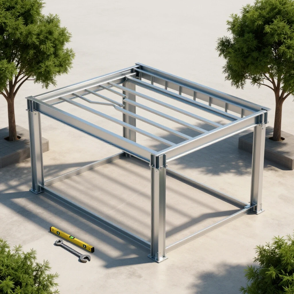
When I plan these adjustable stops, I look at the “telescoping” relationship of the steel. If you use a 2-inch square tube as your rail, a 2.5-inch sleeve with a 3/16-inch wall thickness is a common choice. However, you have to account for the internal weld seam found inside most structural tubing. This “flash” can catch on the inner rail, so I always factor in a 1/16-inch to 1/8-inch total clearance.
- Material Selection: Use A36 mild steel for its predictability and ease of welding.
- Wall Thickness: Opt for 3/16-inch or 1/4-inch for the sleeve to prevent the locking bolt from stripping the threads.
- Clearance: Aim for a total “slop” of 0.0625 inches (1/16th) to ensure the bracket slides even if the trailer rail gets a bit of road grime on it.
Building these components for custom fabrication projects means you aren’t just making a part; you’re making a system. I prefer to sketch the cross-section of the nested tubes first. This helps me visualize where the locking pin will sit and ensures the handle won’t interfere with the trailer sideboards.
Calculating Kerf and Material Allowances for Accurate Cuts
Kerf is the width of the material removed by the saw blade during a cut. Ignoring it leads to parts that are short by 1/16th or 1/8th of an inch, which ruins the alignment of sliding mechanisms. Proper layout requires adding the kerf width to every measurement on your cut list.
In my shop, I use a dry-cut saw with a carbide-tipped blade. The kerf on that blade is exactly 0.090 inches. If I need four sleeve sections at exactly 6 inches each, and I don’t account for the kerf, my last piece will be nearly 3/8 of an inch too short. This is where many garage builders get frustrated. They measure 6 inches, cut on the line, and then wonder why the assembly doesn’t fit the trailer rail.
| Cutter Type | Typical Kerf Width | Accuracy Level | Best Use Case |
|---|---|---|---|
| Abrasive Chop Saw | 1/8″ (0.125″) | Low | Rough structural cuts |
| Carbide Dry-Cut Saw | 3/32″ (0.090″) | High | Precision sliding sleeves |
| Portable Band Saw | 1/32″ (0.035″) | Medium | Notching and small tabs |
| Plasma Cutter | 1/16″ – 1/8″ | Variable | Curved profiles or plates |
To get accurate square cuts, I always mark my line with a scribe rather than a thick soapstone. I then align the blade so it “takes the line”—meaning the edge of the blade just touches the mark, but the kerf falls on the scrap side of the material. This ensures my 6-inch sleeve is exactly 6 inches.
Building Fabrication Fixtures to Control Metal Warping
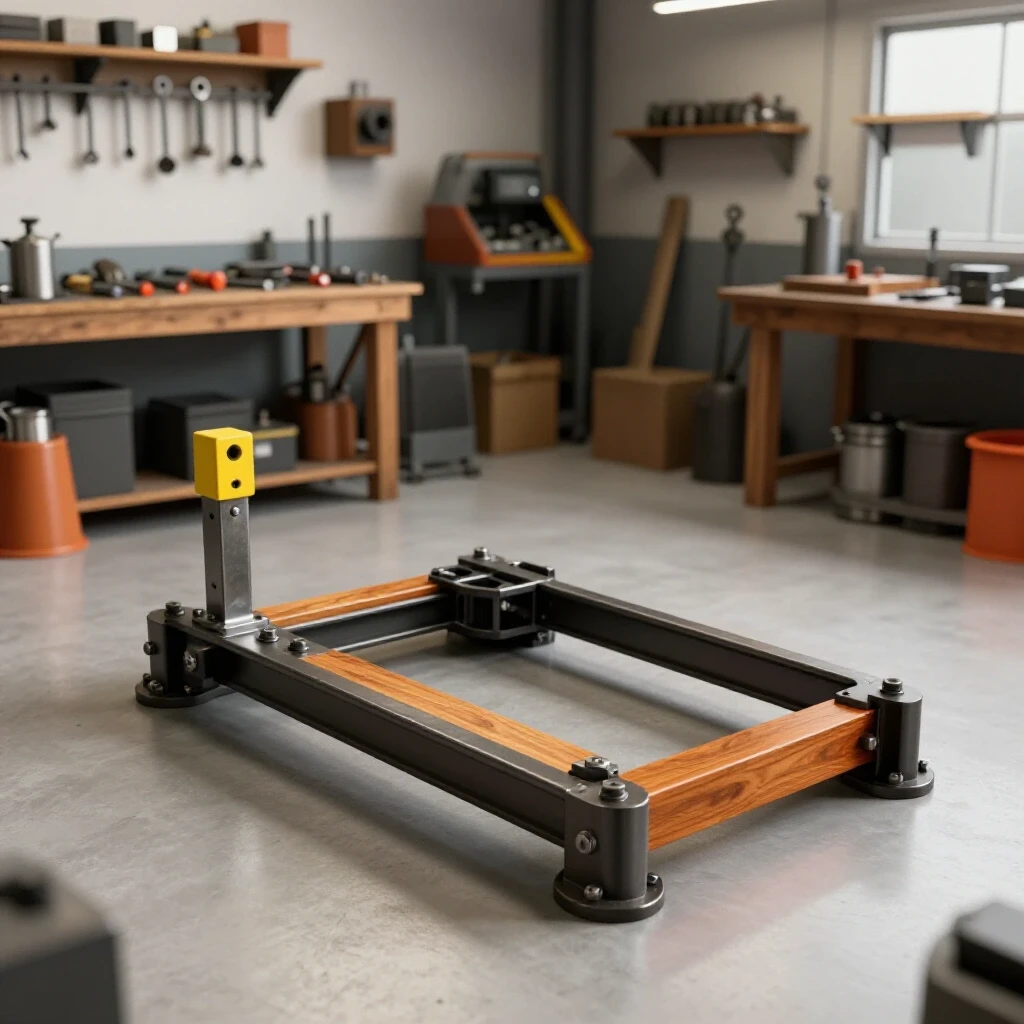
A jig or fixture holds your components in a fixed position during welding. This resists the natural tendency of steel to pull toward the heat. For adjustable stops, a simple fixture ensures the sleeve remains square to the locking nut and the tie-down loop.
I never weld a sliding bracket while it is actually on the trailer. The trailer rail acts as a massive heat sink, which can lead to uneven cooling and warping. Instead, I build a “dummy rail” out of a scrap piece of the same tubing. I wrap the dummy rail in a single layer of heavy-duty aluminum foil or thin shim stock. This creates a tiny bit of extra space so that after the sleeve is welded and cools, it doesn’t shrink-wrap itself onto the bar.
- Fixture Rigidity: Use 3/8-inch plate or heavy angle iron as a base for your jig.
- Clamping Points: Place clamps within 2 inches of every weld joint to restrain the metal.
- Heat Sinks: Copper or aluminum blocks placed inside the tube can help pull heat away and prevent the thin walls from blowing through.
Workshop jigs and fixtures are the secret to repeatability. If you are making four stops for a trailer, the jig ensures the fourth one is identical to the first. I use a “strongback”—a heavy piece of C-channel—to clamp my sleeve components down. This prevents the “bowing” effect that occurs when you weld along the length of a tube.
Mastering Weld Sequencing to Maintain Squareness
Weld sequencing is the order in which you apply heat to a joint. By alternating sides and directions, you use the shrinkage of one weld to counteract the pull of another. This is the most critical step in preventing your cargo stops from seizing.
When metal is heated to a molten state, it expands. As it cools, it contracts more than it expanded. This is called “shrinkage.” If you weld the entire left side of a bracket first, the metal will pull toward that side, creating an angular distortion. To combat this, I use a “balanced” sequence. I weld an inch on the front-left, then move to the back-right.
| Sequence Step | Action | Purpose |
|---|---|---|
| 1. Four-Point Tack | Small tacks at every corner | Establishes basic geometry |
| 2. Opposite Corners | Weld 1″ on diagonal corners | Balances initial pull |
| 3. Center Outward | Weld from the middle of a seam to the edge | Reduces longitudinal bowing |
| 4. Cooling Break | Allow to touch-cool | Prevents heat soak buildup |
I follow a rule of “stitching.” Instead of one long, continuous bead, I use multiple shorter beads. For a 6-inch sleeve, I might do three 2-inch segments. Interestingly, the direction of the weld matters too. If you weld toward a corner, you “push” the heat and the stress into the joint. If you weld away from it, you can sometimes mitigate the peak stress at the corner.
Tacking Strategies for Adjustable Sliding Brackets
Tack welds are small, temporary bonds that hold parts for alignment. They must be strong enough to resist initial heat but small enough to break if adjustment is needed. For sliding stops, tacks should be placed at the points of highest structural stress.
A common mistake is making tacks too small. If a tack is just a “whisker” of metal, the first full weld pass will cause it to snap, and the part will shift. I aim for tacks that are about 1/4 inch long and have good penetration. For a square sleeve, I place one tack on each of the four corners. Before I move to the final welding, I check the “fit-up” by sliding the sleeve over the rail. If it binds, I can easily grind a tack off and realign it.
- Clean the metal: Remove all mill scale within 1 inch of the tack site.
- Square the part: Use a machinist square to verify the 90-degree angles.
- Apply pressure: Use a C-clamp to ensure there is zero gap between the pieces.
- Tack and check: After every two tacks, re-verify the squareness.
In my experience, metal warping solutions often start with the tack. If your tacks are uneven, the final weld will be uneven. I also suggest “opposite tacks”—if you tack the top left, your next tack should be the bottom right. This keeps the internal stresses of the cooling tacks from pulling the part out of square before you even start the main beads.
Final Assembly: Integrating Threaded Rods and Locking Pins
The adjustment mechanism relies on a locking pin or a threaded rod to secure the stop-block. Proper alignment of these holes is critical for smooth operation. Drilling these holes after welding can be difficult due to work-hardening, so I prefer to pre-drill them using a drill press.
To create the locking mechanism, I weld a heavy-duty nut over a pre-drilled hole on the sleeve. I then use a T-handle bolt or a threaded rod to tighten the sleeve against the trailer rail. To ensure the nut stays square during welding, I thread a sacrificial bolt through the nut and into the hole. This keeps the threads clean and the nut centered.
- Hole Alignment: Use a center punch to prevent the drill bit from walking.
- Nut Welding: Only weld two sides of the nut to prevent the heat from distorting the internal threads.
- Thread Protection: Apply anti-seize or a drop of oil to the bolt before you weld the nut to prevent “spatter” from sticking to the threads.
When the weld is finished, I run a tap through the nut. Even with careful sequencing, the heat can slightly ovalize the nut. A quick pass with a tap ensures the locking bolt turns by hand. This is the level of detail that separates a “backyard build” from a professional-grade tool.
Troubleshooting Heat Distortion and Alignment Issues
Even with the best planning, metal can still move. Troubleshooting involves identifying where the pull happened and using “counter-heating” or mechanical force to bring the part back into tolerance. It is important to know when to fix a part and when to start over.
If a sliding sleeve is tight on one side, it usually means the weld on the opposite side pulled too hard. I’ve found that I can sometimes “draw” the metal back by placing a small weld bead on the side that needs to move. As that bead cools, it pulls the metal toward itself. However, this requires a delicate touch. If the distortion is more than 1/16th of an inch over a 6-inch span, I usually use a hydraulic press to gently nudge it back to square.
- Check for “High Spots”: Use a flashlight inside the tube to see where the sleeve is hitting the rail.
- Manual Clearancing: A long-reach file or a flap disc on an angle grinder can remove internal burrs.
- Heat Straightening: Using an oxy-acetylene torch to heat the “long” side of a warp can cause it to shrink back into position when cooled quickly with a wet rag.
One of the metal layout tips I swear by is the “X-measurement.” On any rectangular part of the bracket, measure from corner to corner diagonally. If the two measurements are identical, your part is square. If they differ by more than 1/16th of an inch, you need to address the alignment before the final welding passes.
Conclusion: Putting Your Custom Fabrication Projects to Work
Building your own trailer hardware is a rewarding way to customize your gear for exactly how you use it. By focusing on kerf allowances, rigorous fixturing, and smart weld sequencing, you can create adjustable stops that are as reliable as any commercial version. The key is to respect the physics of the metal. Don’t rush the cooling process, and always check your squareness at every stage.
Once your brackets are finished, I recommend a simple finish of cold galvanizing spray or a heavy-duty primer to prevent rust. Since these parts slide, paint will eventually wear off, so a thin coat of paste wax on the inner rail can keep things moving smoothly for years. Take these lessons into your next build, and you’ll find that the “banana” tubes become a thing of the past.
FAQ: Frequently Asked Questions About Building Adjustable Trailer Stops
How do I prevent the sliding sleeve from sticking after I weld it? The most effective way is to use a “shim” during the tacking process. Place a piece of 16-gauge sheet metal or even a heavy cereal box cardboard between the rail and the sleeve. This creates a tiny gap that accounts for the metal’s natural shrinkage during cooling. Remove the shim before the final heavy welding passes.
What is the best weld sequence for a four-sided sleeve? Start with tacks on all four corners. Then, weld the two sides that are opposite each other. Let them cool to the touch. Finally, weld the remaining two sides. This “opposing side” technique balances the inward pull and keeps the tube from becoming trapezoidal.
Can I use a MIG welder for these brackets, or is TIG better? Both work well, but MIG is generally faster for trailer projects. TIG offers more control over the heat-affected zone (HAZ), which can result in less warping. If you use MIG, keep your wire speed and voltage balanced to ensure deep penetration without excessive heat buildup.
Why did my locking nut strip after only a few uses? This usually happens because the nut was overheated during welding, which softens the steel. It can also happen if the hole in the sleeve wasn’t perfectly aligned with the nut. Always use a Grade 5 or Grade 8 nut for better thread durability, and avoid “over-welding” it.
How much clearance should I leave between the inner rail and the outer sleeve? For a utility trailer, a gap of 1/16th of an inch (0.0625″) is ideal. This is enough to allow for a layer of paint and some road grime without the bracket becoming sloppy or rattling excessively.
Should I weld the tie-down loop to the sleeve or the rail? The loop must be welded to the sliding sleeve. This allows you to move the tie-down point to wherever your cargo requires. Ensure the loop is made of at least 1/2-inch round bar or heavy plate to handle the tension of ratchet straps.
How do I clean the inside of the square tubing after welding? A long-handled wire brush or a small flap wheel on a die grinder works best. You want to remove any “spatter” (small balls of molten metal) that may have jumped inside the sleeve during welding, as these will scratch the rail and cause sticking.
What should I do if the sleeve warps so much it won’t slide? First, identify the “high point” inside the sleeve. You can often grind this down with a file. If the entire tube is bowed, you may need to use a “relief cut”—sawing halfway through the weld to let the metal relax—and then re-welding with better clamping.
Is it necessary to use a drill press for the locking pin holes? While a hand drill can work, a drill press ensures the hole is perfectly perpendicular to the face of the tube. If the hole is at an angle, the locking pin won’t seat flat against the inner rail, which can lead to the bracket slipping under load.
How do I protect the threads of the locking bolt from weld spatter? The easiest way is to use a “spatter guard” spray or simply wrap the bolt threads in a layer of aluminum foil. Alternatively, wait to install the final bolt until all welding and grinding are complete. Use a sacrificial “dummy” bolt during the actual welding process.
(This article was written by one of our staff writers, Robert Kline. Visit our Meet the Team page to learn more about the author and their expertise.)