How to Build a Roll-Out Steel Sheet Storage Rack (DIY Plan)
I remember the first time I tried to build a heavy-duty storage solution for my shop. I had spent a week’s pay on a stack of 11-gauge 4×8 sheets and had them leaned against the wall. One morning, the whole pile slid, nearly pinning my legs and denting the bottom edges of the steel. I decided right then to build a rolling system to manage the weight. I spent hours measuring and cutting 2×2 square tubing, only to realize after welding that the frame had pulled into a diamond shape. My sliding drawers wouldn’t track because I hadn’t respected the physics of weld shrinkage. That project was a hard lesson in why layout and sequencing matter more than the weld bead itself.
In my thirteen years as a prototype technician, I’ve learned that steel is a living thing when you apply heat. It moves, it breathes, and if you don’t restrain it properly, it will ruin your day. For those of you building in a home garage or a small shop, the challenge is even greater because we often lack the massive cast-iron platen tables found in industrial facilities. We have to be smarter with our workshop jigs and fixtures to achieve professional results. This guide focuses on the structural reality of building a mobile, floor-based system designed to hold and organize large metal sheets using a sliding drawer mechanism.
Designing the Foundation for Heavy Material Loads
Planning a floor-based frame requires understanding load distribution and material weight. You must account for the total weight of full steel sheets, which can exceed 1,000 pounds, to ensure the casters and structural members don’t fail under static or dynamic loads. A single 4×8 foot sheet of 10-gauge steel weighs about 185 pounds; a stack of five can easily push your project’s total weight toward a ton when you include the frame.
When I start custom fabrication projects, I always begin with a structural calculation. For a rolling sheet organizer, the base frame takes the brunt of the stress. I prefer using 2″ x 2″ square tubing with a 3/16″ wall thickness for the main perimeter. This provides a high strength-to-weight ratio and a flat surface for mounting your rollers.
- Weight Benchmarks:
- 16-gauge 4×8 sheet: ~82 lbs
- 11-gauge 4×8 sheet: ~150 lbs
- 3/16″ 4×8 plate: ~245 lbs
- Caster Selection: Use phenolic or steel wheels. Rubber will flat-spot under the constant weight of a full rack.
- Safety Factor: Design for 1.5 times your expected maximum load to account for “shock loading” when moving the rack over uneven concrete.
Building on this, your material choice dictates your welding settings. Thicker walls allow for deeper penetration but require more heat, which increases the risk of metal warping. I always source my steel from a local service center rather than a big-box store to ensure I’m getting true A36 mild steel, which has predictable expansion rates.
Mastering the Cut List and Kerf Allowances
Accurate cutting starts with understanding the kerf, or the material removed by the saw blade. In custom fabrication projects, failing to account for a 1/16th-inch or 1/8th-inch blade width across ten cuts can lead to a frame that is significantly undersized or out of square. If your cuts are off by just a hair, your sliding drawers will bind as they move.
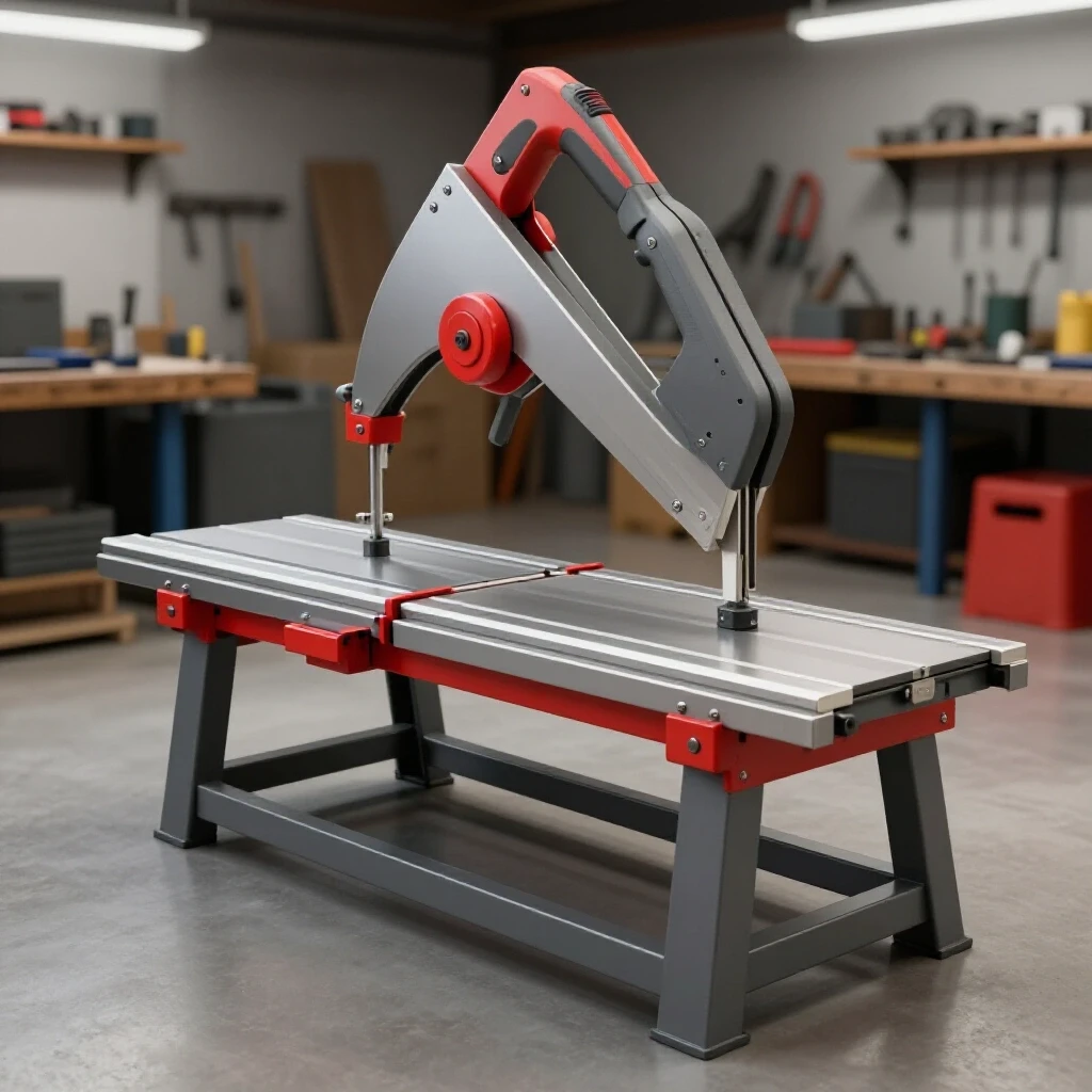
I use a cold saw for most of my work because it leaves a clean, square edge with minimal heat-affected zones. However, if you are using an abrasive chop saw or a portable band saw, you must compensate for the blade’s “drift.” When I mark my steel, I don’t just draw a line; I use a scribe to create a fine groove and always cut on the “waste side” of that line.
| Cutter Type | Typical Kerf Width | Dimensional Tolerance | Best Use Case |
|---|---|---|---|
| Abrasive Chop Saw | 3/32″ – 1/8″ | +/- 1/16″ | Rough framing |
| Portable Band Saw | 1/32″ – 1/16″ | +/- 1/32″ | On-site fitting |
| Cold Saw | 1/16″ | +/- 1/64″ | Precision drawer tracks |
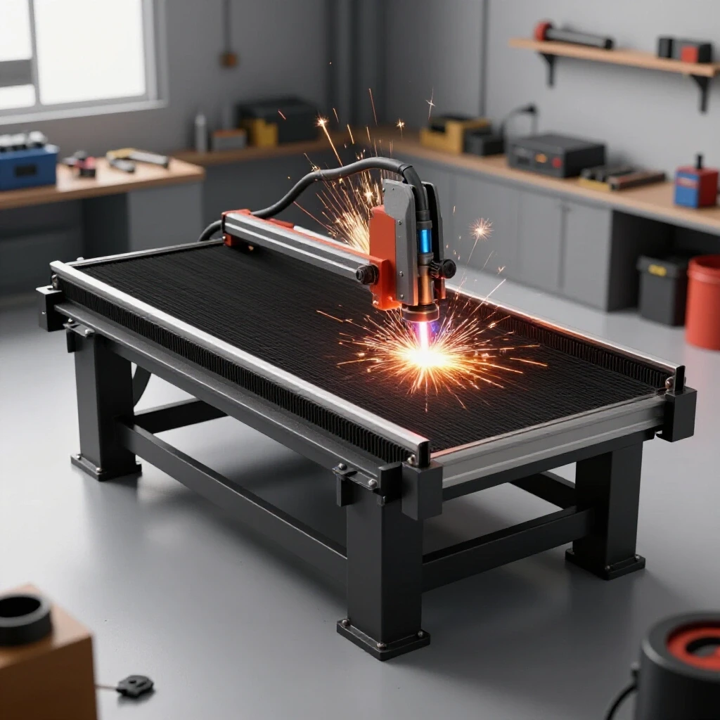
| Plasma Cutter | 1/16″ – 1/8″ | +/- 1/8″ | Plate gussets |
Interestingly, many builders forget to account for the thickness of the material itself when calculating the “inside” dimensions of a frame. If you want a drawer to be exactly 49 inches wide to hold a 48-inch sheet with some wiggle room, and you are using 2-inch tubing, your exterior frame width must be 53 inches. Double-checking these metal layout tips before the first spark flies saves hours of grinding later.
Establishing Workshop Jigs and Fixtures for Alignment
A workshop jig is any temporary structure used to hold parts in a fixed position during assembly. For a large-scale sheet storage project, your floor is rarely flat enough to serve as a reference surface. You need to create a level plane using sawhorses or a dedicated welding table to prevent the frame from “propellering” or twisting.
If you don’t have a professional fixture table, I recommend building a “strongback” jig. This is essentially two long, straight pieces of heavy C-channel or I-beam leveled on your floor. You clamp your frame members to these beams. This forces the tubing to stay on a single plane while you apply the initial tacks.
- Leveling: Use a machinist’s level, not a standard carpenter’s level.
- Clamping: Use F-style clamps every 12 to 18 inches.
- Squaring: Use the 3-4-5 triangle method or measure diagonals. For a 4×8 frame, the diagonals should be approximately 107 11/16 inches. If they are within 1/16th of an inch of each other, you are ready to tack.
As a result of proper fixturing, you reduce the physical labor required to “force” pieces into alignment later. I once saw a builder try to pull a 1/4-inch twist out of a base frame using a 20-ton jack. It didn’t work. The steel has a memory, and it’s much easier to keep it straight from the start than to fix it after the welds have cooled.
Structural Tacking and the Physics of Heat Pull
A tack weld is a small, temporary bead used to hold components in place before final welding. In custom fabrication, the size and placement of these tacks are critical because they must be strong enough to resist the initial “pull” of the cooling metal but small enough to be easily consumed or ground away during the final pass.
When you weld one side of a joint, the liquid metal shrinks as it solidifies. This creates an angular pull, drawing the two pieces of steel toward the weld. To combat this, I always place tacks on opposite sides of the joint. If I’m joining a vertical upright to a base frame, I place a 1/4-inch tack on the “outside” corner, then immediately place another on the “inside” corner.
- Tack Size: For 3/16″ tubing, aim for tacks that are 1/4″ long with good penetration.
- Tack Spacing: On long runs, space tacks every 6-8 inches.
- The “Opposite” Rule: Always tack in pairs. If you tack the top, tack the bottom next.
- Inspection: After tacking the entire assembly, re-measure your diagonals. This is your last chance to make easy corrections.
If your frame has moved out of square after tacking, you can usually “bump” it back into place with a dead-blow hammer. However, if you’ve already laid a 2-inch bead, that joint is locked. I’ve had to cut apart entire sub-assemblies because I got overconfident and skipped the mid-build measurement check. Don’t let the excitement of the build override the discipline of the tape measure.
Executing the Weld Sequencing Layout to Control Warping
Weld sequencing is the specific order in which you apply beads to a project to balance the heat input and minimize distortion. By strategically jumping from one side of the frame to the other, you allow the cooling forces of one weld to counteract the cooling forces of another. This is the most effective of all metal warping solutions.
For a rectangular frame, never weld all four sides of one corner before moving to the next. This concentrates too much heat in one spot, causing the metal to expand and then contract violently. Instead, use a “staggered” approach. Weld the top of corner A, then the top of corner C (the opposite corner). Then weld the top of corner B and corner D.
| Sequence Step | Location | Purpose |
|---|---|---|
| 1 | Corner A – Top | Initial structural bond |
| 2 | Corner C – Top (Diagonal) | Balances longitudinal pull |
| 3 | Corner B – Top | Establishes the second axis |
| 4 | Corner D – Top (Diagonal) | Completes the top plane |
| 5 | All Corners – Vertical Down | Seals the uprights without excessive heat |
| 6 | All Corners – Inside Fillets | Final structural reinforcement |
As you progress, monitor the temperature of the steel. If the metal is glowing dull red for more than a few seconds after you stop welding, you are putting in too much heat. I often keep a compressed air nozzle nearby to move air over the joints, though I avoid “quenching” with water, as this can make the mild steel brittle. Consistent, moderate heat is your friend; localized, extreme heat is your enemy.
Integrating the Roll-Out Mechanism for Sheet Access
The heart of a sliding material organizer is the roller or drawer system. Because steel sheets are heavy and thin, they need support along their entire bottom edge to prevent bowing. In my builds, I typically use heavy-duty cam followers or steel rollers rated for at least 500 pounds each, mounted to a sub-frame that slides within the main chassis.
The tolerance for these tracks is tight—usually within +/- 1/32nd of an inch. If your main frame warped during welding, your drawers will bind. This is why I wait to weld the final track supports until the main frame is fully cooled and checked for squareness. I often use “bolt-on” tracks for the rollers, which allows for fine-tuning and shimming if the welding process caused minor deviations.
- Track Alignment: Use a laser level to ensure the left and right tracks are perfectly parallel.
- Roller Clearance: Leave 1/16″ of “float” in the rollers to account for small debris or mill scale on the tracks.
- Stop Blocks: Always weld heavy-duty stop blocks at the end of the tracks. You do not want 1,000 pounds of steel rolling out of the frame and onto your shop floor.
Building on this, consider the handle and pull mechanism. You are moving a significant amount of mass. A simple 1-inch round bar handle welded at waist height provides the necessary leverage. I also recommend a “locking pin” system to keep the drawers retracted when you are moving the entire rack around the shop.
Final Straightening Techniques and Surface Finishing
Even with the best weld sequencing, some minor distortion is inevitable. Metal warping can be corrected using “flame straightening” or mechanical force, but these require a gentle touch. For a storage rack, the most common issue is a slight “bow” in the long horizontal members.
If a tube has bowed upward, you can apply a small amount of heat to the “high” side of the bend. As the spot cools, it will contract more than the surrounding metal, pulling the tube back toward straight. This is a technique I learned early in my career as a prototype technician, and it feels like magic when you see the steel move. However, be careful—overheating can weaken the structural integrity of the A36 steel.
- Check for “Wind”: Sight down the length of the frame to check for twists.
- Grinding: Clean all welds with a 40-grit flap disc. Avoid removing too much material from the throat of the weld, as this reduces strength.
- Degreasing: Use acetone or a dedicated wax and grease remover. Mill scale and shipping oil will prevent paint from adhering.
- Coating: A high-quality industrial enamel or “chassis black” paint works best. It resists the scratches and dings that come from loading and unloading heavy steel sheets.
Once the paint is dry, I recommend applying a thin layer of paste wax to the sliding tracks. This reduces friction and prevents rust from forming in the areas where the rollers have stripped the paint. It’s a small detail, but it makes the rack feel like a piece of precision machinery rather than a clunky shop fixture.
Case Study: The 2,500-Pound Capacity Vertical Organizer
To put these principles into perspective, let’s look at a build I completed last year. The goal was to store ten sheets of varying thicknesses. I used a “toaster rack” design where each sheet lived in its own sliding vertical drawer. The total material cost was approximately $450, including the heavy-duty casters and the steel.
The biggest challenge was the “angular weld shrinkage” on the upright supports. Because the uprights were 50 inches tall, a tiny 1-degree pull at the base resulted in the top of the drawer being nearly an inch out of alignment. I solved this by using a temporary “spacer bar” tacked across the top of the drawers during the welding process. This acted as a workshop jig, holding the tops at exactly 2.5 inches apart while I welded the bases.
- Total Time: 16 hours (4 hours layout/cutting, 8 hours welding/assembly, 4 hours finishing).
- Accuracy Achieved: Diagonals within 1/16″; all drawers slide with one-hand operation.
- Lessons Learned: I initially tried to use 1/8″ wall tubing for the drawers, but it flexed too much under the weight of 1/4″ plate. I had to switch to 3/16″ wall for the bottom rails.
This build proved that taking the time to plan the weld sequencing layout is the difference between a tool that helps your workflow and a frustrating piece of scrap metal. By controlling the heat and respecting the material’s properties, you can build shop furniture that rivals anything found in a professional fab shop.
Conclusion and Next Steps for Your Build
Building a robust system for material management is a rite of passage for any serious fabricator. It tests your ability to maintain tight dimensional tolerances and manage the thermal stresses of welding on a large scale. If you follow the steps of accurate layout, strategic tacking, and disciplined sequencing, you will end up with a rack that serves your shop for decades.
Your next step is to measure your most common sheet sizes and draft a simple cut list. Don’t forget to account for your saw’s kerf and the thickness of your casters. Start by cleaning your workspace and ensuring you have a level area to begin your layout. Remember, the quality of your finished project is determined in the first hour of layout, not the last hour of welding.
Frequently Asked Questions
What is the best way to ensure my base frame is perfectly square?
The most reliable method is measuring the diagonals of the rectangle. If the distance from the top-left corner to the bottom-right corner is identical to the distance from the top-right to the bottom-left, the frame is square. For a large frame, use a steel tape measure and ensure it doesn’t sag, as this can give a false reading.
Why do my welds always pull the metal toward the bead?
When steel is heated to a liquid state, it expands. As it cools and solidifies, it contracts. Since the weld bead is the hottest part and is fused to the cooler surrounding metal, the contraction “pulls” the surrounding pieces inward. This is known as angular distortion or weld shrinkage.
Can I build this project using a standard 110V MIG welder?
A 110V welder can handle 1/8″ material easily, but for a heavy-duty rack using 3/16″ or 1/4″ steel, you may struggle with penetration. If you use a 110V machine, you must use a multi-pass technique and potentially pre-heat the joints with a torch to ensure the weld is structurally sound.
How do I prevent the sliding drawers from binding?
Binding is usually caused by the tracks not being parallel. Use a spacer block (a piece of wood or steel cut to the exact width) to check the distance between the tracks at the front, middle, and back of the frame. If the distance varies by more than 1/16th of an inch, you need to adjust your mounts.
What type of casters should I use for a rack holding 2,000 lbs?
Look for casters with a “dynamic load rating” that exceeds your total weight. For a 2,000-lb rack, I suggest four casters rated at 800 lbs each. This provides a safety margin. Swivel casters with locks are best for the front, while rigid casters on the back help the rack track straight when being pushed.
How thick should the steel be for the sheet supports?
For the bottom rail that carries the actual weight of the sheet, 3/16″ wall square tubing or C-channel is standard. If you are only storing thin-gauge sheets (20-gauge or thinner), you could drop down to 1/8″, but for general shop use, the extra rigidity of 3/16″ is worth the cost.
Should I weld the casters directly to the frame or bolt them on?
I always recommend bolting casters to a mounting plate that is welded to the frame. Casters are wear items; the bearings will eventually fail or the wheels will chip. If they are bolted on, replacement takes five minutes. If they are welded, it’s a major repair job.
How do I calculate the kerf for my specific saw?
Take a scrap piece of metal and make a partial cut. Measure the width of the slot created by the blade using a set of calipers. That measurement is your kerf. Most abrasive saws have a 1/8″ kerf, while band saws are closer to 0.035″ to 0.045″.
What is the “3-4-5 rule” for squaring?
This is a geometric principle where if one side of a triangle is 3 units long and the adjacent side is 4 units long, the hypotenuse must be 5 units long for the corner to be exactly 90 degrees. In a shop setting, you can use 3 feet, 4 feet, and 5 feet to check the corners of your large base frame.
Is it necessary to grind off the mill scale before welding?
Yes. Mill scale is a layer of oxidized iron that forms during the hot-rolling process. It has a higher melting point than the steel itself and can cause weld defects like porosity or lack of fusion. Use a grinding disc or a wire wheel to clean the steel to “bright metal” at least one inch away from every joint.
(This article was written by one of our staff writers, Robert Kline. Visit our Meet the Team page to learn more about the author and their expertise.)