How to Build a Mobile Pneumatic Air Tool Cart (DIY Guide)
There is a specific kind of frustration that only a fabricator understands. You spend three hours measuring, cutting, and degreasing steel for a new rolling shop station. You clamp everything down, check it with a precision square, and run your first bead. By the time the metal cools, that “perfect” 90-degree corner has pulled into an 87-degree mess. I’ve been there more times than I care to admit. During my thirteen years as a prototype technician, I learned that metal isn’t a static material; it is a living, breathing thing that moves when you apply heat.
When I first started building custom shop equipment, I ignored the physics of weld shrinkage. I thought I could “muscle” the steel back into place with a sledgehammer. It never worked. Today, I approach every custom fabrication project with a plan that accounts for thermal expansion and mechanical pull. Building a dedicated workstation for your air compressors and pneumatic tools requires more than just sticking metal together. It requires a structured approach to layout, fixturing, and sequencing to ensure the final product stays true and rolls straight.
Designing the Frame and Establishing Dimensional Tolerances
Design planning is the process of creating a visual and mathematical roadmap for your build before the first cut is made. This stage identifies the required footprint, load-bearing capacity, and storage needs for your air-powered equipment while setting strict limits on how much error is acceptable during construction.
I always start with a hand-drawn blueprint on graph paper or a basic CAD layout. For a mobile unit holding a compressor and heavy impact wrenches, I aim for a dimensional tolerance of +/- 1/16th of an inch. Anything wider than that and your casters won’t track correctly, or your shelves will rattle. I prefer using 1.5-inch square tubing with a 1/8-inch wall thickness for the main uprights. It provides a great balance between weight and rigidity.
When you are planning the base, remember that the center of gravity is crucial. A tall, narrow cart holding a heavy compressor is a tipping hazard. I generally design the base to be at least 4 inches wider than the compressor tank itself. This extra width provides a “buffer zone” for mounting hose reels or external manifolds without making the unit feel top-heavy.
Calculating Kerf Allowances for Accurate Square Cuts
Kerf is the width of the material removed by a cutting tool during the fabrication process. Calculating kerf allowances involves adding the thickness of the blade’s path to your measurements to ensure the final pieces match your intended dimensions exactly after they are separated from the raw stock.
In my early days, I would mark a line at 24 inches and cut right down the middle of it. I’d end up with a piece that was 23 and 15/16ths inches long. That 1/16th of an inch might not seem like much, but across four corners, it creates a massive alignment headache. Different tools have different “appetites” for metal.
- Abrasive Chop Saw: Usually leaves a 1/8-inch kerf and creates significant heat.
- Cold Saw: Leaves a very clean 0.090-inch to 0.100-inch kerf with minimal heat.
- Portaband/Bandsaw: Typically leaves a 0.045-inch to 0.060-inch kerf.
- Plasma Cutter: Can leave a kerf of 0.060-inch to 0.125-inch depending on the tip and speed.
| Cutting Tool | Average Kerf Width | Accuracy Level | Best Use Case |
|---|---|---|---|
| Abrasive Saw | 0.125″ (1/8″) | Low | Rough framing |
| Cold Saw | 0.095″ | High | Precision chassis work |
| Bandsaw | 0.050″ | Medium-High | General fabrication |
| Angle Grinder | 0.040″ – 0.060″ | Low-Medium | Field repairs/Short cuts |
Establishing a Level Layout with Workshop Jigs and Fixtures
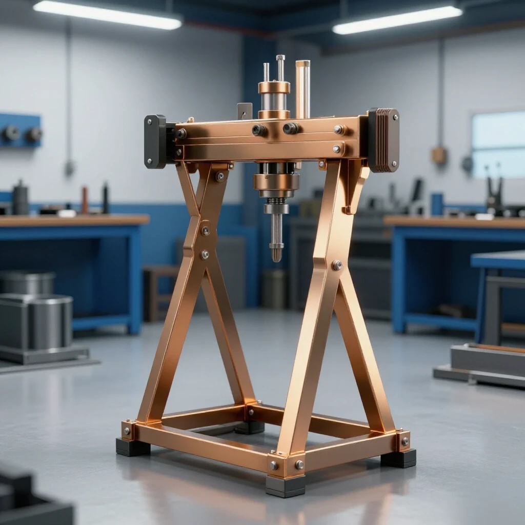
Workshop jigs and fixtures are temporary or permanent structures used to hold workpieces in a fixed position during the assembly and welding process. They act as a “third hand” that maintains alignment and resists the forces of weld shrinkage, ensuring the project remains square and true.
You cannot build a straight cart on an uneven garage floor. I learned this the hard way when I built a utility trailer that looked like a potato chip because my driveway had a 2-degree slope for drainage. Now, I use a dedicated fixture table or a set of heavy-duty saw horses leveled with a digital protractor.
For custom fabrication projects, I often build a “picture frame” jig out of scrap angle iron. I tack four pieces of angle iron into a perfect rectangle on my table. This creates a pocket where I can drop my frame members. This physical restraint is your first line of defense against metal warping solutions. If the metal is physically blocked from moving inward, it is much easier to maintain your 90-degree corners.
The Physics of Weld Shrinkage and Angular Distortion
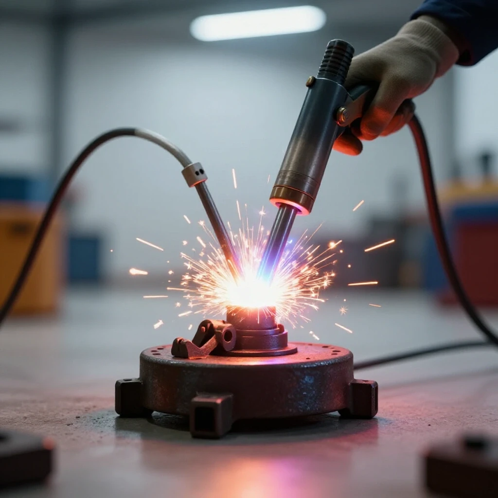
Weld shrinkage is the contraction of metal as it cools from a molten state back to room temperature. This phenomenon creates internal stresses that pull the surrounding metal toward the weld bead, often resulting in “angular distortion” where two perpendicular pieces are pulled into an acute angle.
When you lay a bead of molten steel, it expands. As it cools, it shrinks significantly more than it expanded. Think of the weld bead like a cooling rubber band that is being stretched across your joint. It wants to pull the two pieces of metal together. In a standard T-joint, the weld will pull the vertical upright toward the side where the bead was laid.
To combat this, I use a technique called “preset.” If I know a weld is going to pull my upright by 2 degrees, I might clamp it at 92 degrees before welding. However, a more reliable method for most builders is robust tacking and specific sequencing. By placing tacks on opposite sides of the joint, you create “anchors” that fight the shrinkage forces from both directions.
Strategic Tack Welding for Structural Alignment
Tack welding is the application of small, temporary welds used to hold components in place before the final structural beads are laid. Effective tacking involves sizing the tacks appropriately for the material thickness and spacing them to provide maximum resistance against thermal pulling.
A common mistake I see is making tacks too small. A “whisker” of a tack will snap the moment the metal starts to move. For 1/8-inch wall tubing, your tacks should be about 1/4-inch long and have good penetration. I follow a “Four-Point” tacking rule for square tubing:
- Place a tack on the outside corner.
- Check for square using a machinist’s square.
- Place a tack on the opposite inside corner.
- Check for square again.
- Place tacks on the remaining two sides.
If you find that your frame has pulled out of square after the first two tacks, don’t keep welding. Cut the tacks with a thin zip-disk on your grinder, realign, and try again. It is much easier to fix a 1/4-inch tack than a 4-inch structural bead.
Executing a Symmetric Weld Sequencing Layout
Weld sequencing is the strategic order in which beads are applied to a structure to balance the heat input and shrinkage forces. By alternating sides and “jumping” around the project, a builder can ensure that the pull from one weld is offset by the pull of another, maintaining overall dimensional accuracy.
If you weld all the way around one joint before moving to the next, you are asking for a warped frame. I use a “staggered” approach. I might weld the front-left corner, then move to the back-right corner. This allows the heat to dissipate and prevents any one area from becoming a “hot spot” that pulls the entire assembly out of alignment.
| Step | Location | Side | Purpose |
|---|---|---|---|
| 1 | Corner A | Outside | Initial anchor |
| 2 | Corner C (Diagonal) | Outside | Balance longitudinal pull |
| 3 | Corner B | Outside | Establish width |
| 4 | Corner D (Diagonal) | Outside | Complete outer perimeter |
| 5 | Corner A | Inside | Counteract Step 1 |
| 6 | Corner C | Inside | Counteract Step 2 |
This sequence ensures that the “pull” is always being fought by a weld on the opposite side of the structure. I also recommend welding from the center of a joint outward toward the edges, which helps push the heat away from the most critical alignment points.
Mounting Casters and Ensuring a Stable Base
Caster mounting involves attaching swivel or fixed wheels to the base of the structure, requiring a flat mounting surface and reinforced attachment points. Proper placement ensures the cart can handle the weight of the compressor and tools while remaining easy to maneuver on varied shop floors.
I prefer using 4-inch polyurethane casters with total-lock brakes. For a mobile pneumatic station, I always mount the casters to a “mounting plate” made of 3/16-inch plate steel rather than welding them directly to the tubing. This reinforces the corners of the frame and provides a flat surface for the caster’s ball-bearing race.
When welding these plates, I use a “stitch weld” pattern—1 inch of weld, 2 inches of space. This prevents the thin wall of the tubing from blowing through and keeps the plate from warping. If the mounting plate warps, the caster won’t sit flat, and the cart will have a “death wobble” when you try to roll it across the shop.
- Cut four 4″x4″ plates from 3/16″ mild steel.
- Drill holes to match your caster bolt pattern.
- Clamp the plate to the bottom of the frame corner.
- Tack all four corners of the plate.
- Weld in 1-inch increments, alternating between corners.
Integrating Pneumatic Manifolds and Hose Storage
Pneumatic integration involves adding the functional components—such as manifolds, hose reels, and tool hangers—that turn a metal frame into a specialized air tool station. This requires planning for the weight of the hose and the ergonomics of tool access.
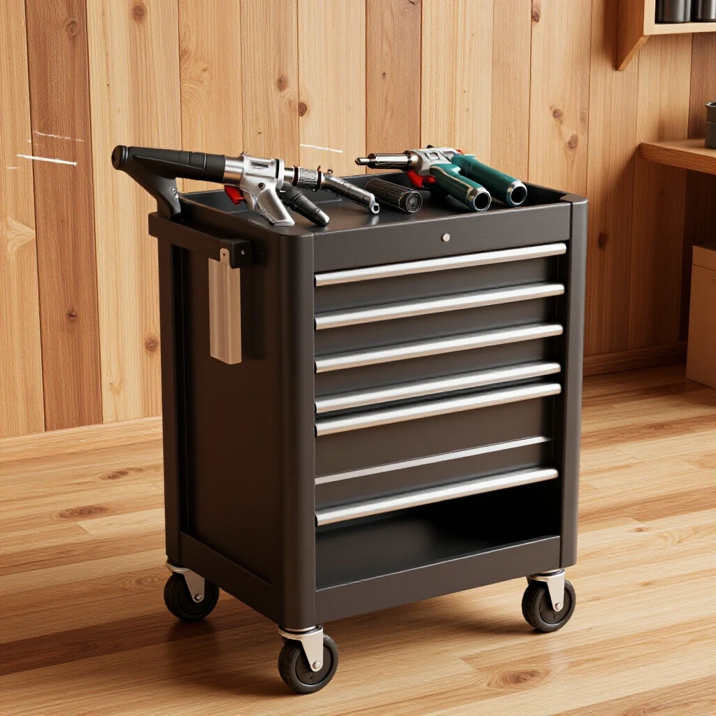
A great air tool cart needs a way to organize the “spaghetti” of hoses. I like to weld a vertical 1-inch pipe or a large “U” hook made of 1/2-inch round bar to the side of the uprights. This provides a sturdy place to coil 50 feet of air hose. For the tools themselves, I weld short lengths of 1-inch angle iron with the “V” facing up. This creates a perfect cradle for impact wrenches and air ratchets.
If you are mounting a manifold, consider using “blind nuts” or “rivnuts” in the square tubing. This allows you to bolt the manifold on after painting, making it easier to replace or upgrade later. I usually position the manifold at waist height (about 36 inches) so I don’t have to bend over to plug in my tools.
Managing Heat with Heatsinks and Cooling Rates
Heat management is the practice of controlling the temperature of the metal during welding to minimize the size of the heat-affected zone (HAZ). Using copper or aluminum heatsinks can draw heat away from the joint, reducing the overall thermal expansion and subsequent warping.
If you are welding thin-gauge sheet metal for a tool tray, warping is almost guaranteed without heat control. I keep a few thick blocks of aluminum in my shop. I clamp these right next to my weld path. Aluminum absorbs heat much faster than steel, acting like a “thermal sponge.”
Also, resist the urge to quench your welds with water to cool them down faster. Rapid quenching can make the steel brittle and increase internal stresses, leading to cracks. Let the metal air-cool until you can touch it with a gloved hand before removing your clamps or jigs. This “rest period” allows the molecular structure of the steel to stabilize.
Final Straightening and Post-Weld Corrections
Post-weld correction is the process of identifying and fixing any minor misalignments that occurred despite your best efforts during the build. This can involve strategic heating, mechanical force, or shimming to ensure the final project meets its design specifications.
Even with the best weld sequencing layout, you might find a corner that is 1/16th of an inch out of square. If the frame is “racked” (diamond-shaped), you can often use a heavy-duty ratcheting cargo strap. Hook it to the “long” corners and tension it until the frame is pulled back into square, then add a small gusset or a shelf to lock it in place.
For minor “bows” in a long piece of tubing, you can use “flame straightening.” Briefly heat the side of the tube opposite the bow with an oxy-acetylene torch until it’s dull red, then let it air cool. As that spot shrinks, it will pull the tube back toward straight. This is an advanced technique, so practice on scrap first.
Checklist for a Successful Build Sequence
To keep your project on track, follow this structured checklist. I use a similar log for every custom fabrication project to ensure I don’t skip the “boring” prep work that leads to a high-quality result.
- Verify Material Squareness: Check that the ends of your raw stock are actually square before measuring.
- Calculate Total Kerf: Subtract your blade width from your total material length to ensure you have enough steel.
- Clean the Joints: Remove all mill scale and oil within 2 inches of every weld.
- Set the Fixture: Clamp your base members to a known flat surface.
- Tack and Measure: Place tacks and check the “X” measurement (diagonal corners). They must be identical.
- Execute Sequence: Follow your staggered weld plan to distribute heat.
- Inspect for Pull: Check squareness after every four inches of welding.
- Mount Mobility Hardware: Ensure casters are level and plates are fully supported.
- Add Utility Features: Weld on hose hangers, tool cradles, and compressor mounts.
- Final Clean: Grind down any sharp edges and prep for a durable finish.
Conclusion: Building for the Long Haul
Fabrication is as much about discipline as it is about skill. When you take the time to calculate your kerf, build a proper jig, and follow a logical weld sequence, you aren’t just building a cart; you are practicing the fundamentals of precision engineering. My most successful projects weren’t the ones where I welded the fastest; they were the ones where I spent the most time with my square and my clamps.
As you move forward with your build, remember that metal behavior is predictable. If you treat heat as a force to be managed rather than an obstacle to be ignored, your projects will start coming off the table straighter, stronger, and more professional. Take your time, trust your measurements, and don’t be afraid to cut a tack if things aren’t looking right. The goal is a tool that serves your shop for decades.
FAQ: Common Challenges in Custom Metal Fabrication
How do I prevent my square tubing from twisting when I weld the corners? Twisting is usually caused by uneven heat on the sides of the tube. To prevent this, ensure your tacks are balanced on all four sides of the joint before laying a full bead. Use a fixture table to clamp the tubing flat against a known surface, which limits the metal’s ability to rotate as it cools.
What is the best way to check if my frame is square if I don’t have a large enough square? Use the “3-4-5 rule” or measure the diagonals. If you measure from the top-left corner to the bottom-right, and then from the top-right to the bottom-left, those two numbers must be exactly the same. If they differ, your frame is “racked” into a parallelogram.
How many tacks should I use on a 1.5-inch square tube joint? I recommend four tacks—one in the center of each flat side. This provides equal resistance against pulling in all directions. For structural shop projects, each tack should be about 3/16″ to 1/4″ in diameter with good penetration into the base metal.
Should I weld the top or the bottom of the cart frame first? Always start with the most rigid part of the structure, which is usually the base frame. Once the base is welded and square, it acts as a “master jig” for the uprights and the top shelf. If your base is crooked, everything built on top of it will be crooked too.
Why does my welder “blow through” the metal when I get near the edges? Heat builds up at the edges of the metal because there is nowhere for it to go. To prevent blow-through, start your weld about 1/4-inch away from the edge and weld toward the center, or use a “copper backing bar” held behind the joint to soak up the excess heat.
How do I account for the thickness of the paint when building tight-fitting tool holders? A standard coat of primer and enamel can add 0.005 to 0.010 inches to the surface. If you are building a tight-fitting cradle for a pneumatic tool, add 1/16th of an inch of “slop” to your dimensions to ensure the tool still fits after the cart is painted.
What is the best way to mount a heavy air compressor to a metal cart? Never weld the compressor tank directly to the frame. This can create stress points that lead to tank failure. Instead, weld mounting tabs to the frame and use rubber vibration isolation pads between the compressor feet and the cart, securing them with Grade 5 bolts.
How can I tell if I’ve warped the frame beyond repair? If a corner is out of square by more than 1/4-inch over a 12-inch span, it will be difficult to correct without cutting the joint open. Small deviations (under 1/8-inch) can often be hidden or corrected with strategic heating, but larger warps usually require a “do-over” to maintain structural integrity.
Does the type of welding (MIG vs. TIG) affect how much the metal warps? Yes. TIG welding generally introduces more total heat into the part because the process is slower, which can lead to more warping if not managed. MIG welding is faster and more localized, which often results in less overall distortion for general shop projects like tool carts.
What should I do if my casters don’t all touch the ground at the same time? This is a sign that your base frame is twisted. You can often fix this by “shimming” the low caster. Place a thin metal washer between the caster mounting plate and the frame before bolting it down. This is a common “real-world” fix for frames that aren’t perfectly flat.
(This article was written by one of our staff writers, Robert Kline. Visit our Meet the Team page to learn more about the author and their expertise.)