How to Build a Comfortable Steel Shop Stool with Seat (Plan)
I have spent thirteen years in fabrication shops, and if there is one thing I have learned, it is that metal has a mind of its own. I remember my first major custom fabrication project—a heavy-duty utility trailer. I had every piece cut to the exact sixteenth of an inch. I clamped it down, felt confident, and started laying long, beautiful beads. By the time the metal cooled, the entire frame had twisted like a pretzel. It was a humbling lesson in the physics of heat. Metal expands when hot and contracts as it cools, and if you do not have a plan to manage that movement, your project will never be square.
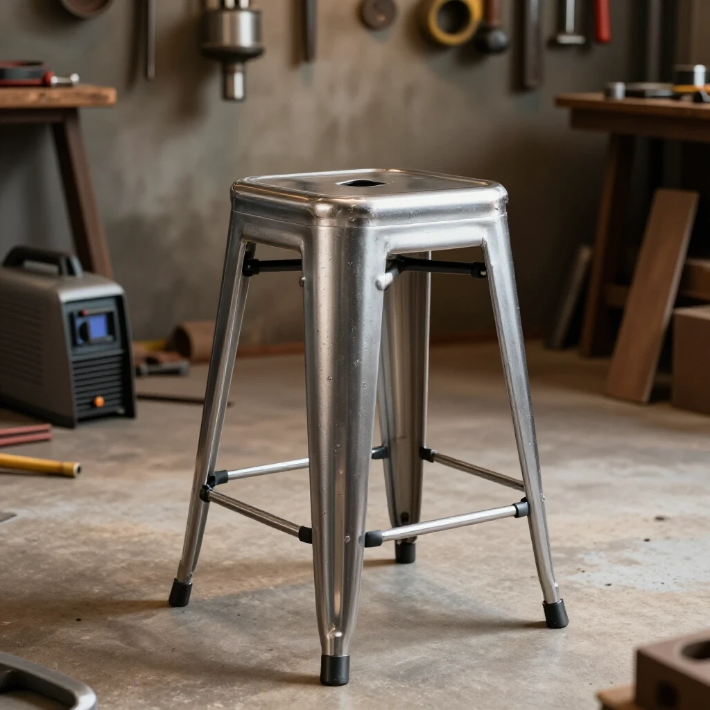
Building a stable, level place to sit in the shop is the ultimate test of these fundamentals. If a trailer is slightly out of true, you might not notice it at highway speeds for a while. But if a shop chair has legs that are off by just an eighth of an inch, you will feel that wobble every single time you sit down. This guide focuses on the technical precision required to build a rugged seating unit from square and round steel tube, ensuring it stays flat, square, and stable through smart layout and weld sequencing.
Planning the Framework and Calculating Material Kerf
Planning involves translating a design into a precise list of cuts while accounting for the width of the saw blade. This step prevents the finished frame from being too short or out of alignment because it factors in the physical space removed by the cutting tool during the fabrication process.
When I start a project, I do not just look at the final dimensions; I look at the “cut-to-cut” reality. For a standard seating height of 28 to 30 inches, you need to account for the thickness of the seat pan and the floor glides. If you are using 1-inch square tubing with a 1/8-inch wall thickness (11 gauge), your measurements must be dead-on.
The most common mistake is ignoring the kerf. The kerf is the width of the material removed by the saw blade. If you use a standard abrasive chop saw, your kerf might be 1/8 of an inch. If you make ten cuts without accounting for this, your final assembly could be over an inch short.
Table 1: Material Kerf Allowances by Tool Type
| Cutting Tool | Typical Kerf Width | Best Use Case |
|---|---|---|
| Abrasive Chop Saw | 1/8″ to 5/32″ | Bulk cutting of thick wall tube |
| Cold Saw (Carbide) | 3/32″ to 1/8″ | Precision cuts with minimal burr |
| Portaband (Portable) | 1/32″ to 1/16″ | Notching and field adjustments |
| Angle Grinder (Thin) | 1/16″ | Detailed trimming and tight spots |
I always mark my steel with a scribe or a fine-point silver pencil rather than a thick soapstone. A soapstone mark can be 1/16 of an inch wide on its own. If you cut on the wrong side of that line, you have already doubled your error. For this project, I recommend a +/- 1/16-inch tolerance for all leg components to ensure the base sits level on a flat shop floor.
Building Workshop Jigs for Frame Alignment
Jigs are temporary structures used to hold metal pieces in the exact position required for welding. They act as an extra set of hands to ensure every corner remains at 90 degrees and prevent the parts from shifting under the pressure of clamps or the pull of a cooling weld.
You do not need a professional $5,000 welding table to get square results. I often build “disposable” jigs right on my workbench using scrap angle iron. For a shop stool, the goal is to keep the four legs and the cross-braces perfectly indexed. I suggest creating a “ladder jig.” This is simply two long pieces of heavy channel or thick-wall tube clamped to your table, spaced exactly the width of your stool frame.
When you drop your cut pieces into this fixture, they cannot move left or right. I also use “squaring blocks”—small L-shaped pieces of 1/4-inch plate—tacked to the table at the corners. By pushing your tubing into these blocks and clamping them down, you ensure the 90-degree angle is maintained before the first arc is struck.
- Verify the table surface is flat using a 4-foot straight edge.
- Lay out the first side of the stool frame (two legs and the connecting rungs).
- Clamp the legs against a straight reference bar.
- Use a framing square to check the rungs.
- Measure the diagonals. If the distance from the top-left corner to the bottom-right corner matches the top-right to bottom-left, the frame is square.
Controlling Metal Warping through Strategic Weld Sequencing
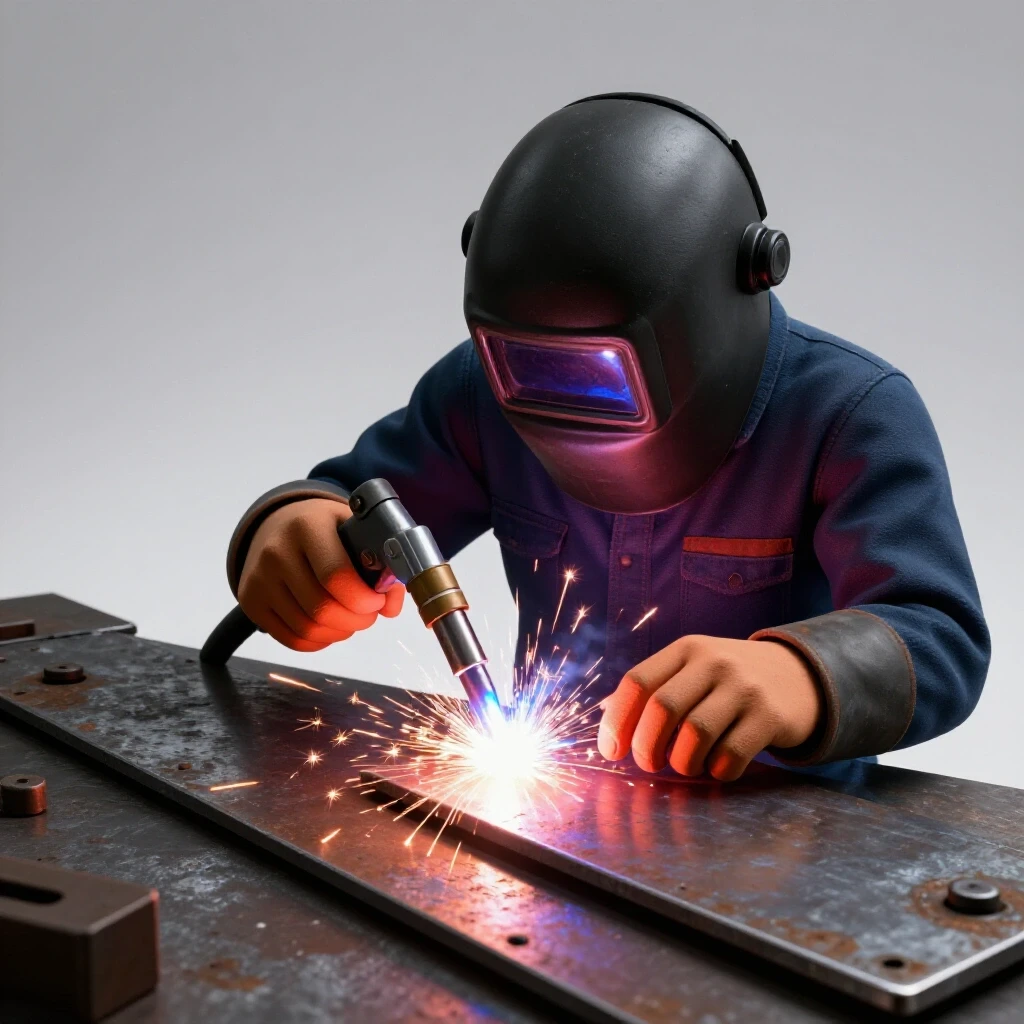
Weld sequencing is the planned order in which you apply heat to a joint. By alternating sides and positions, you use the natural shrinkage of cooling metal to pull the structure back into square rather than out of it, balancing the internal stresses of the steel.
I have seen many builders weld one entire joint from start to finish before moving to the next. This is a recipe for a twisted frame. Think of a weld bead like a cooling rubber band. As it transitions from liquid to solid, it shrinks. This shrinkage exerts a massive amount of force on the joint, pulling the metal toward the side where the weld was placed.
To combat this, I use a “staggered” approach. I never finish a joint in one go. Instead, I move around the project, placing small tacks first, then short beads on opposite sides. This distributes the heat evenly across the entire structure.
Table 2: Weld Sequencing and Distortion Control Strategy
| Action Step | Purpose | Result |
|---|---|---|
| Corner Tacking | Secure geometry with minimal heat | Holds parts at 90 degrees |
| Opposite Side Tacking | Balance the initial pull | Prevents the joint from “opening up” |
| Root Pass (Inside) | Establish structural base | Pulls the joint slightly inward |
| Cover Pass (Outside) | Final strength and aesthetics | Pulls the joint back toward square |
| Cooling Intervals | Allow heat to dissipate | Reduces cumulative thermal expansion |
For a stool frame, I tack all four corners of a side panel. Then, I flip the panel over and tack the back sides. Only after the entire “ladder” is tacked and checked for square do I begin the final welding. I weld the outside corners first, then the inside, moving from the bottom rung to the top.
Managing Heat Distortion and Angular Pull
Heat distortion is the permanent change in shape caused by the expansion and contraction of metal during welding. Angular pull occurs when the weld bead cools and “draws” the two pieces of metal toward each other, often turning a 90-degree corner into an 88-degree corner.
In custom fabrication projects, you have to accept that metal will move. The trick is knowing how much. In my experience with 1/8-inch wall square tubing, a full-length fillet weld can pull a joint by about 1 to 2 degrees. If you are building a stool that is 30 inches tall, a 1-degree pull at the top can result in the bottom of the leg being nearly half an inch out of place.
To manage this, I use “pre-setting” or “back-stepping.” Pre-setting involves clamping the piece slightly past square in the opposite direction of the weld pull. When the weld cools, it pulls the piece into the correct 90-degree position. Back-stepping involves welding in short segments, moving in the opposite direction of the overall bead progress. This limits the amount of heat concentrated in one area at one time.
- Tack size: For 11-gauge tube, tacks should be about 3/16 of an inch.
- Tack spacing: Place a tack at every corner of the tube profile (four tacks per joint).
- Heat control: If the metal glows dull red for more than a second after you stop welding, you are moving too slowly or using too much amperage.
- Clamping: Keep the project clamped to the jig until the metal is cool enough to touch with a gloved hand. Removing clamps too early allows the “residual stress” to warp the frame.
Final Assembly and Attaching the Seat Pan
This final phase involves squaring the top frame, drilling mounting holes, and securing the seating surface. It focuses on ergonomics and structural stability, ensuring the stool can handle the weight and movement of a busy fabricator without flexing or failing.
Once you have two identical side panels, it is time to join them with the remaining cross-members to create the 3D box of the stool. This is where most builders struggle because they no longer have a flat table to reference. I use “magnetic squares” and “bridge clamps” to hold the cross-members in place while I check the verticality of the legs.
For the seat pan, I prefer using 10-gauge or 12-gauge sheet steel. It provides a solid base that won’t oil-can (flex and pop) when you sit on it. I drill four 5/16-inch holes in the top of the frame for mounting. Interestingly, I don’t weld the seat pan directly to the frame in most cases. Instead, I use a thin layer of high-density foam or rubber between the steel pan and the frame, then bolt it down. This prevents the “ringing” sound of metal-on-metal and makes the stool much more comfortable for long hours at the bench.
- Drilling: Use a center punch to prevent the drill bit from walking on the square tube.
- Deburring: Always use a countersink bit or a larger drill bit to remove the sharp burrs from the holes.
- Leveling: Place the completed frame on a known flat surface (like a table saw top or a thick steel plate). If one leg is high, do not immediately grind the bottom. Check if the frame is twisted first.
- Straightening: If a leg is slightly out of alignment, you can use a “heat shrink” technique. Briefly heat the side opposite the lean with a torch and then quench it with a wet rag. The rapid contraction will pull the leg back into line.
Accurate Layout Tips for Custom Fabrication Projects
Layout is the foundation of every successful build. If your marks are wrong, your cuts will be wrong, and your weld sequence won’t matter because the geometry is already flawed. I rely on a few specific tools and techniques to maintain tight dimensional tolerances.
First, I always use a “story pole.” Instead of measuring every piece of tubing individually with a tape measure—which can lead to cumulative errors—I mark all my lengths on a single piece of scrap wood or a long strip of steel. I then use this master template to mark every leg and every rung. This ensures that even if my measurement is off by 1/32, it is off by the same 1/32 on every single piece, which keeps the project symmetrical.
Second, I pay close attention to the “mill scale.” This is the dark, flaky outer layer on hot-rolled steel. You must grind this off at every weld location. Mill scale is an insulator and contains impurities that can cause porosity in your welds. A clean joint requires 1/2 inch of shiny, bare metal on all sides of the weld zone.
Checklist for Layout Accuracy:
- Confirm the squareness of your tools: Check your framing square against the “3-4-5 rule” to ensure it is actually 90 degrees.
- Account for tube radius: Remember that square tubing has rounded corners. Your measurements should be based on the flat faces, not the apex of the curve.
- Scribe your lines: A knife edge or metal scribe is more accurate than a marker.
- Double-check the “long point”: If you are mitering corners, always double-check if your measurement is for the inside or outside of the angle.
Correcting Heat Distortion After Welding
Even with the best sequencing, some movement is inevitable. A seasoned fabricator knows how to “read” the metal and apply corrective forces. If the stool frame has a slight rock, the first step is to identify which leg is the culprit.
I use a set of feeler gauges or thin shims to measure the gap under the floating leg. If the gap is less than 1/16 of an inch, I can usually fix it by slightly “stretching” the opposite corner. This involves placing a heavy weight on the high side and giving the frame a firm, controlled bounce. For larger distortions, I use a “mechanical pull.” I clamp the frame to the table with a spacer under the low point and apply downward pressure to the high point, effectively “cold-setting” the steel back to square.
- Avoid over-grinding: Do not grind your welds flush to “fix” a fitment issue. This significantly weakens the joint.
- Use a port-a-power: If you have access to a small hydraulic ram, it is the best tool for pushing a frame back into alignment without damaging the surface.
- Check for “diamonding”: Look down the top of the stool. If the square looks like a diamond, one side is longer than the other, or the tacks pulled unevenly.
Conclusion and Next Steps
Building a durable shop stool is more than just sticking metal together; it is a lesson in geometry and thermal dynamics. By focusing on accurate kerf calculations, building rigid workshop jigs, and following a strict weld sequencing layout, you can create a piece of furniture that is as straight and stable as a factory-made unit.
The most important takeaway is to respect the heat. Don’t rush. Let the metal cool between passes. Use your clamps as if your project’s life depends on them, because its squareness certainly does. Once you master these metal warping solutions on a small project like this, you will have the confidence to tackle larger custom fabrication projects, like workbenches or even vehicle frames, with the same level of precision.
Your next step is to head to the steel yard. Pick up some 1-inch, 11-gauge square tubing and a piece of 10-gauge plate. Start by building your corner jigs on your workbench. Once your layout is locked in, the rest is just a matter of following the sequence.
FAQ: Common Questions About Building Steel Shop Seating
How do I stop my stool legs from pulling inward when I weld the rungs? This is caused by angular pull. To prevent it, place heavy tacks on the outside of the leg-to-rung joint first. You can also “over-spread” the legs by about 1/16 of an inch using a spreader clamp before welding. As the weld cools, it will pull the legs back to the vertical position.
What is the best welding process for a shop stool: MIG or Stick? MIG (Metal Inert Gas) is generally preferred for shop furniture because it produces less heat-affected zone (HAZ) and less spatter, making it easier to maintain dimensional tolerances. However, Stick welding is perfectly fine if you use a smaller diameter electrode (like 3/32″ 7018) and keep your amperage low to avoid blowing through the tube wall.
Why does my stool wobble even though all my cuts were the same length? The wobble usually comes from “diamonding” or “twisting” during the assembly of the two side panels. If the cross-members are not perfectly square to the side panels, the entire structure will twist. Always check the diagonals of the footprint (the distance between opposite feet) to ensure they are equal.
How thick should the seat pan be for a 250lb person? For a standard 12×12 or 14×14 inch seat, 12-gauge (approx. 0.104″) steel is the minimum I recommend. If you want zero flex, go with 10-gauge (approx. 0.134″). Anything thinner will likely require a cross-brace underneath to prevent the metal from “popping” when you sit down.
Should I weld the joints all the way around? Yes, for a shop stool, you should weld all four sides of the tube. This prevents moisture from getting inside the tubing, which causes internal rust. It also provides the structural rigidity needed to handle the lateral forces when you lean back or move the stool across the floor.
How do I get a smooth finish on the corners without weakening the weld? Use a flap disc (60 or 80 grit) instead of a hard grinding wheel. A flap disc is more forgiving and allows you to blend the weld into the tubing surface without gouging the base metal. Only grind the weld flush on the top surface where the seat pan sits; leave a slight “fillet” on the other sides for strength.
Can I build this without a welding table? Yes. You can use a flat concrete garage floor, but you must verify it is level first. Use shims to get your jig pieces flat. However, a waist-high surface is much better for maintaining accurate layouts and making precise welds.
What is the best way to attach feet to the stool? I recommend welding a threaded nut (like a 3/8-16) inside the bottom of each leg or using plastic “knock-in” glides. If you weld a flat plate to the bottom of the leg, make sure to drill a small “weep hole” to allow gasses to escape during welding and to prevent pressure buildup.
How much gap should I leave between pieces for welding? For 1/8-inch wall tubing, you don’t need a significant gap. A “tight fit” (zero gap) is usually best for MIG welding to prevent burn-through. If you are Stick welding, a tiny gap (the thickness of a business card) can help with penetration, but it increases the risk of the joint pulling out of square.
How do I calculate the angle for the legs if I want them flared out? A 5-degree flare is standard for stability. To calculate the cut, use a miter saw set to 5 degrees. Remember that a flared leg requires a compound cut if it flares in two directions, which is much more difficult to jig. For your first stool, I recommend keeping the legs vertical for simplicity.
(This article was written by one of our staff writers, Robert Kline. Visit our Meet the Team page to learn more about the author and their expertise.)