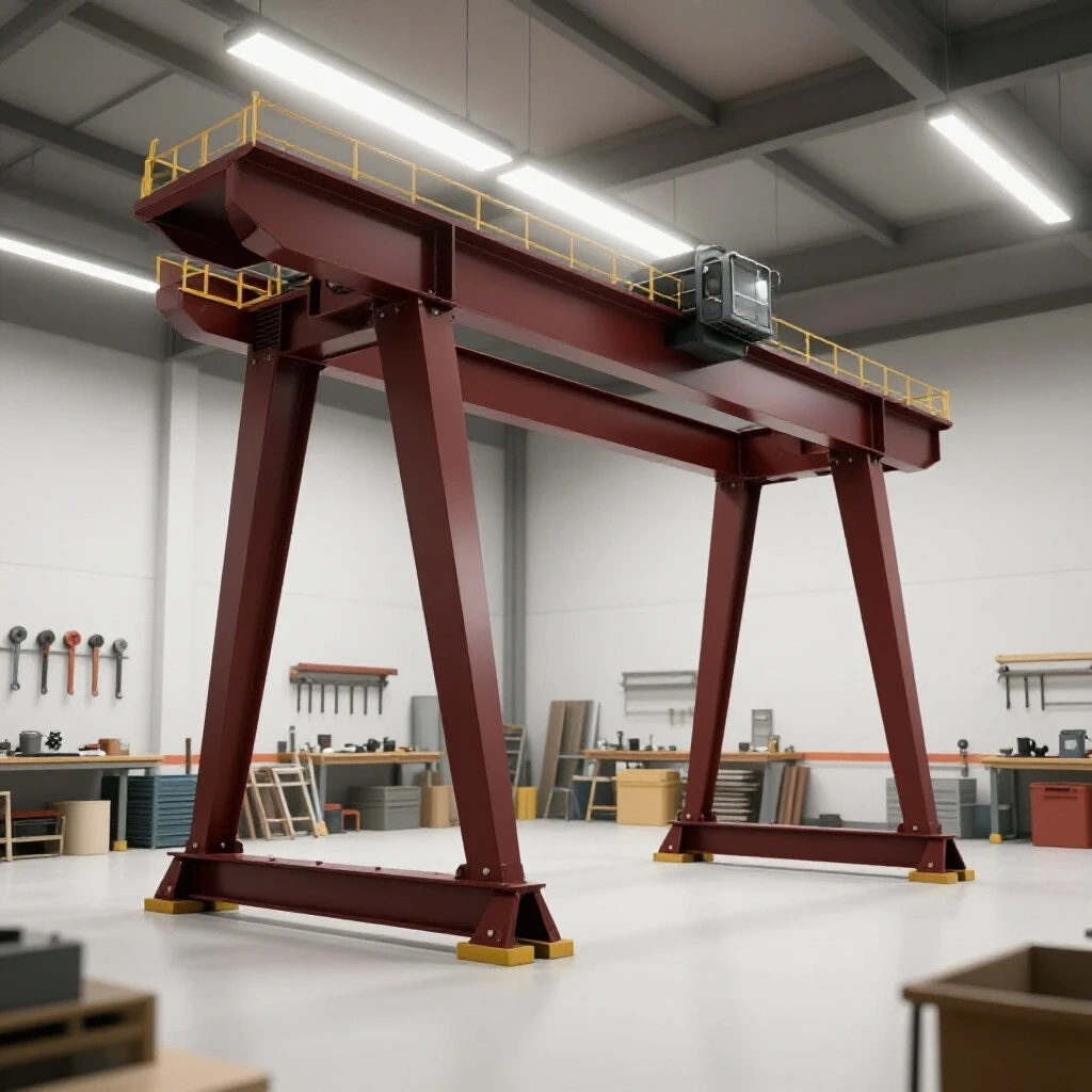
How to Build a Rigid Heavy Steel Lathe Stand (DIY Tutorial)
I remember the first time I built a heavy machine base in my home shop. I had spent a week’s worth of pay on 3-inch square tubing and a thick steel top plate. I measured everything twice, used a high-quality square, and felt confident as I started laying down beads. But as the metal cooled, I watched in horror as one corner lifted nearly a half-inch off the floor. The heat from my welds had pulled the entire frame into a trapezoid. That project taught me a hard lesson: steel is not a static material. It moves, breathes, and fights you every step of the way. When you are building a foundation for a metal lathe, that movement is your primary enemy.
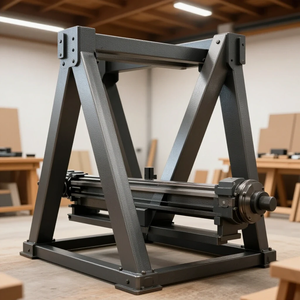
Precision machining requires a base that is both dead-level and incredibly rigid. If your stand flexes, your lathe bed will twist, and your parts will never be truly round. Over my 13 years as a prototype technician, I have developed a system for managing these forces. This guide will walk you through the process of constructing a heavy-duty steel support structure that stays straight and handles the vibration of a spinning workpiece.
Engineering a High-Mass Machine Foundation
A high-mass foundation is a structure designed with heavy-wall steel sections to provide maximum rigidity and dampen the vibrations generated by rotating machinery. This ensures the lathe remains stable during heavy cuts.
When you start planning your custom fabrication projects, the first choice is material thickness. For a lathe weighing between 500 and 1,500 pounds, I recommend nothing less than 1/4-inch wall square tubing. Thinner material, like 1/8-inch or 11-gauge, might seem strong enough to hold the weight, but it lacks the mass needed to absorb harmonics. If the stand is too light, the whole machine will “sing” or vibrate when you take a deep cut, leaving a poor surface finish on your work.
I prefer using 3×3-inch or 4×4-inch square tubing for the main uprights and 2×4-inch rectangular tubing for the horizontal stretches. The rectangular shape offers better resistance to vertical deflection. Building on this, you must also consider the mounting surface. A 1/2-inch or 3/4-inch thick steel plate top is ideal. It provides a flat, stable plane where you can drill and tap holes to bolt the lathe down securely.
- Main Uprights: 3″ x 3″ x 1/4″ Square Tubing
- Horizontal Rails: 2″ x 4″ x 1/4″ Rectangular Tubing
- Mounting Plates: 1/2″ or 3/4″ Hot Rolled Steel Plate
- Gussets: 1/4″ Flat Plate
Calculating Kerf and Planning Your Cut List
Kerf refers to the width of the material that is turned into dust or chips by your cutting tool. Failing to account for this 1/16th or 1/8th of an inch can result in a frame that is significantly shorter than intended.
In my early days, I would mark a line and cut right down the middle of it. By the time I had four pieces cut, I was nearly half an inch short on my total length. To avoid this, you need to know exactly how much material your saw removes. A standard abrasive chop saw might have a 1/8-inch kerf, while a cold saw or a high-quality bandsaw might only be 0.040 inches.
Interestingly, the type of cut also matters. If you are mitering your corners at 45 degrees, any error in the kerf calculation is doubled across the joint. I find it much easier and more structural to use butt joints for these heavy stands. They are easier to square up and provide more surface area for the weld.
| Cutting Tool Type | Typical Kerf Width | Dimensional Tolerance |
|---|---|---|
| Abrasive Chop Saw | 1/8″ (0.125″) | +/- 1/16″ |
| Portable Bandsaw | 1/32″ (0.031″) | +/- 1/32″ |
| Cold Saw | 0.080″ | +/- 0.010″ |
| Plasma Cutter (Handheld) | 1/16″ – 3/32″ | +/- 1/8″ |
Creating Workshop Jigs for Square Alignment
Workshop jigs are temporary fixtures or frames used to hold steel components in a precise 90-degree orientation during the assembly process. They act as an extra set of hands that do not move when the heat is applied.
You do not need a professional welding table to get accurate results. I often build my jigs right on the concrete floor if it is reasonably level. I use “L-shaped” fixtures made from scrap angle iron. By clamping your tubing into these heavy angle iron jigs, you force the pieces to stay at 90 degrees while you apply your initial tacks.
As a result of using these fixtures, you reduce the “spring-back” effect. When steel is heated, it expands; as it cools, it contracts and pulls toward the weld. If the piece is not physically restrained by a jig, that pull will ruin your alignment before you even finish the first bead. I recommend using at least two heavy C-clamps or F-style clamps per joint to keep the tubing tight against the jig.
Structural Tacking and Joint Preparation
Joint preparation involves grinding a bevel into the edges of the steel to allow for deep weld penetration. Tacking is the process of using small, strong welds to hold the structure together before the final welding begins.
For 1/4-inch wall tubing, you cannot just butt the pieces together and weld. You must grind a 30-to-45-degree bevel on the ends of your tubes. This creates a “V” groove that allows the weld metal to reach the root of the joint. Without this, your weld is just sitting on the surface, and the vibration of the lathe could eventually crack the joint.
You want a tack that is strong enough to hold the weight but small enough that you can weld over it smoothly. For this type of heavy stand, I use tacks that are about 1/2-inch long. I place them on the corners first, then check for square again. If the frame has pulled, a 1/2-inch tack can be “persuaded” with a heavy dead-blow hammer. A full bead cannot.- Clean all mill scale off the steel at the weld zones using a flap disc.
- Grind a 1/8-inch land and a 45-degree bevel on all joining edges.
- Position the pieces in your jig and clamp them firmly.
- Place one tack on the top of the joint.
- Check for square using the 3-4-5 triangle method.
- Place a second tack on the opposite side to balance the pull.
Managing Thermal Expansion and Weld Sequencing
Weld sequencing is the strategic order in which you apply welds to different parts of the frame to counteract the pulling forces of cooling metal. Proper sequencing prevents the frame from twisting or “parallelogramming.”
This is where most DIY builders run into trouble. If you weld all the joints on the left side of the stand and then move to the right, the left side will contract and pull the whole frame out of alignment. To combat this, I use a “cross-pattern” sequence, similar to how you tighten lug nuts on a car wheel.
Building on this principle, you should also use “back-stepping.” Instead of running a long bead from one end to the other, you break the weld into shorter segments. You start a few inches away from your previous weld and work back toward it. This distributes the heat more evenly and reduces the total amount of shrinkage in a single direction.
| Weld Order | Position | Purpose |
|---|---|---|
| Sequence 1 | Inner Corners | Sets the initial squareness of the frame. |
| Sequence 2 | Outer Corners (Diagonal) | Balances the pull from the inner tacks. |
| Sequence 3 | Top Flats | Locks the vertical uprights to the rails. |
| Sequence 4 | Vertical Downs | Finalizes the structural integrity of the legs. |
Vibration Dampening and Leveling Provisions
Leveling provisions are adjustable feet or threaded inserts that allow you to compensate for uneven floors. Vibration dampening involves adding mass or specific contact points to reduce the transfer of energy from the machine to the floor.
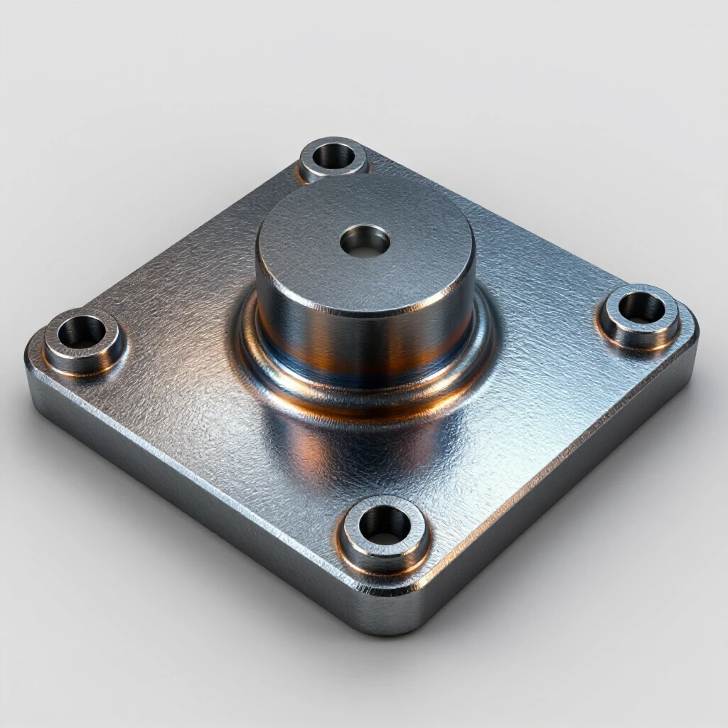
A lathe must be level to operate correctly. If one leg is slightly higher than the others, the bed of the lathe will twist under its own weight. I always weld a thick (1/2-inch) plate to the bottom of each leg. I then drill and tap these plates for 5/8-inch or 3/4-inch leveling bolts. Use fine-thread bolts if possible, as they allow for much more precise adjustments.
Interestingly, the feet should be as wide as possible to provide a stable footprint. I often use heavy-duty machine mounts with rubber pads on the bottom. These pads help isolate the vibration, preventing the lathe’s hum from traveling through the floor and into the rest of your shop. If you find the stand is still too light, you can weld caps on the tubing and fill the legs with dry sand or steel shot before sealing them. This adds significant mass without increasing the footprint.
- Tapped Plate Thickness: 1/2″ minimum.
- Leveling Bolt Diameter: 5/8″ or 3/4″ (Grade 5 or 8).
- Foot Diameter: 3″ to 4″ for stability.
- Adjustment Range: +/- 1 inch.
Accurate Square Cuts and Metal Layout Tips
Metal layout is the process of marking your steel with high precision before any cutting or welding begins. Accurate square cuts are the foundation of a project that fits together without large gaps.
I never use a standard carpenter’s pencil for layout on steel. The line is too thick, often 1/16th of an inch or more. Instead, I use a carbide-tipped scriber or a very fine soapstone marker. When you are aiming for a tolerance of +/- 1/16th of an inch, the width of your marking line matters.
To ensure your cuts are square, always check your saw’s fence. Even a brand-new saw can be out of alignment from the factory. I use a machinist’s square to set the fence 90 degrees to the blade. As a result, my pieces fit together with almost no gaps. If you have a gap larger than 3/32 of an inch, the weld will pull significantly more as it tries to bridge that space.
- Scribe your cut line all the way around the tube.
- Align the saw blade to the “waste” side of the line to account for kerf.
- Use a slow, steady feed rate to prevent the blade from wandering.
- Deburr every cut immediately with a file or grinder.
- Verify the length against your master cut list before moving to the next piece.
Final Straightening Techniques for Warped Frames
Final straightening involves using controlled heat or mechanical force to bring a finished assembly back into its intended dimensions after welding is complete.
Even with the best sequencing, some warping is almost inevitable. If you find that your top mounting surface is not perfectly flat, you can use “heat shrinking” to fix it. This involves heating a small spot on the side opposite the warp with an oxy-acetylene torch. As the spot cools, it contracts and pulls the metal back.
However, be careful. This is an advanced technique that can easily make the problem worse if you overdo it. I prefer to use a heavy-duty hydraulic jack and some stout chains if a frame needs minor straightening. By applying pressure in the opposite direction of the warp and letting it sit overnight, you can often “train” the steel back into position.
Step-by-Step Construction Checklist
Following a structured checklist ensures that no critical steps are missed and that the project progresses logically.
- Preparation: Verify all dimensions on your blueprint and double-check your material count.
- Cutting: Execute all cuts, accounting for kerf, and deburr all edges.
- Joint Prep: Grind 45-degree bevels on all load-bearing joints.
- Layout: Mark the positions of the uprights on the horizontal rails using a scriber.
- Jigging: Secure the first corner into your 90-degree jig and clamp it down.
- Tacking: Apply 1/2-inch tacks to all corners, checking for square after every two tacks.
- Sequencing: Begin final welding using the cross-pattern and back-stepping method.
- Leveling: Weld on the bottom plates and install the leveling feet.
- Mounting: Position the top plate, tack it in several places, and weld in short 2-inch segments to prevent the plate from bowing.
- Finishing: Grind any sharp edges and apply a durable industrial coating or paint.
Summary of Technical Benchmarks
To ensure your project meets professional standards, keep these benchmarks in mind throughout the build.
- Dimensional Tolerance: Aim for +/- 1/16″ across the total length of the frame.
- Squareness: The diagonals of the frame should be within 1/8″ of each other.
- Weld Penetration: Ensure 100% root penetration on all beveled joints.
- Flatness: The top mounting surface should be flat within 1/32″ over the length of the lathe bed.
- Heat Control: If the steel is glowing cherry red more than an inch away from the weld, you are moving too slowly or using too much heat.
Building a rock-solid foundation for your machinery is a rite of passage for any serious shop fabricator. It requires patience, a deep understanding of how metal reacts to heat, and a commitment to accuracy that goes beyond “good enough.” When you finally bolt your lathe down and see that first perfect, vibration-free ribbon of steel peel off a workpiece, you will know that the extra effort in the fabrication stage was worth every second.
FAQ
How do I prevent the top plate from warping when I weld it to the frame? The best way is to avoid continuous beads. Weld in 1-inch to 2-inch segments, jumping from one side of the plate to the other. Allow the steel to cool until you can touch it with a gloved hand before starting the next set of welds. This minimizes the total heat buildup that causes the plate to “potato chip” or bow in the center.
Should I use MIG or TIG for this type of fabrication? MIG is generally preferred for heavy machine stands because it is faster and provides excellent penetration on thick-walled tubing. TIG offers more control and less heat-affected zone (HAZ), but it can be much slower on a large project. For 1/4-inch steel, a MIG welder with .035 wire is a perfect choice.
Why is my frame square before welding but crooked after? This is caused by angular weld shrinkage. As the weld puddle cools, it acts like a tiny winch, pulling the two pieces of steel toward the bead. If you only weld one side of a joint, it will pull in that direction. You must balance your welds on both sides of the tube to keep the pulling forces equal.
Can I use 2×2 tubing instead of 3×3 to save money? I would advise against it for a lathe stand. While 2×2 tubing can technically hold the weight, it lacks the torsional rigidity needed to prevent the stand from twisting when the lathe is running. A lathe creates significant leverage forces; a wider, heavier tube resists these forces much better.
What is the best way to check for square on a large frame? The most accurate method is measuring the diagonals. Measure from the top-left corner to the bottom-right corner, then do the same for the other side. If the two measurements are identical, your frame is perfectly square. Even a 1/8-inch difference means the frame is a parallelogram.
How do I handle mill scale before welding? Mill scale is the dark, flaky coating on hot-rolled steel. You must remove it using a flap disc or a wire wheel at every location where you plan to weld. If you weld over mill scale, it will contaminate the weld, leading to porosity and a much weaker joint.
Is it necessary to fill the legs with sand? It is not strictly necessary, but it is a very effective low-cost way to dampen vibration. If you find your lathe has a “resonance” at certain speeds, adding mass to the legs can shift that resonance frequency and make the machine run much smoother.
What size leveling feet should I use for a 1,000-pound lathe? I recommend 5/8-inch or 3/4-inch diameter bolts. While smaller bolts might hold the weight, they can bend if you ever need to slide the stand across the floor. Heavy-duty bolts provide the lateral strength needed to keep the stand stable.
How do I ensure the top plate is perfectly flat? No rolled steel plate is perfectly flat. However, you can shim the lathe bed itself when you bolt it to the plate. Use thin brass or steel shim stock between the lathe’s feet and the stand’s top plate to dial in the final level of the machine bed.
Should I paint or powder coat the stand? A high-quality industrial enamel paint is usually best for a shop environment. It is easy to touch up if you scratch it or decide to weld on an accessory later. Powder coating is durable but difficult to repair if it chips, and it can be expensive for a large, heavy structure.
How do I calculate the weight of the steel before I buy it? Most steel suppliers provide weight-per-foot charts. For example, 3x3x1/4 square tubing weighs approximately 8.8 pounds per foot. Multiply the total footage of your cut list by the weight per foot to estimate the final weight of your stand and ensure your floor can handle the load.
What is the “3-4-5 rule” for squaring? This is a geometric method where you measure 3 inches (or feet) along one rail and 4 inches (or feet) along the joining rail. If the diagonal distance between those two points is exactly 5 inches (or feet), the corner is a perfect 90-degree angle. This is more accurate than small squares for large frames.
(This article was written by one of our staff writers, Robert Kline. Visit our Meet the Team page to learn more about the author and their expertise.)