How to Build Repeatable Drilling Jigs for Batch Runs (Tips)
I remember standing in my garage a few years ago, staring at a pile of sixty steel gussets that all needed a 1/2-inch hole drilled exactly 1 inch from the corner. I tried to measure and center-punch each one individually. By the tenth piece, my eyes were tired. By the twentieth, I realized my “eyeballed” center marks were drifting. When I tried to bolt the first few gussets onto the frame, the holes didn’t line up. I had wasted three hours and a fair amount of expensive flat bar. That was the day I stopped treating every hole like a new project and started building dedicated fixtures for my drill press.
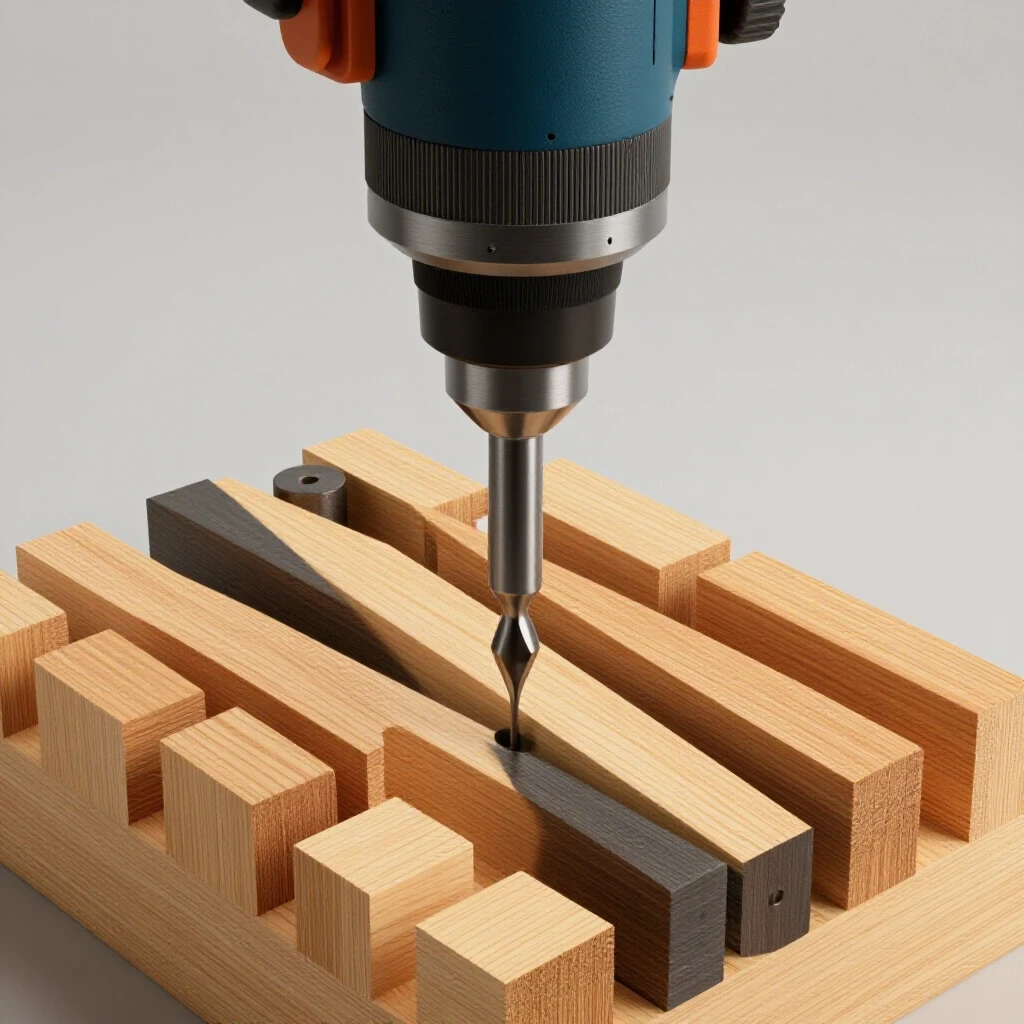
In my thirteen years as a prototype technician, I have learned that consistency is the enemy of the “measure-as-you-go” mindset. If you are making more than ten of anything, you need a way to lock in your coordinates. This guide is about how I build simple, rugged templates that allow me to churn out dozens of identical parts with high precision using nothing more than a standard drill press and some scrap steel.
Establishing a Reliable Baseline for Batch Hole Placement
Designing a template involves mapping out hole centers and stop locations to ensure every part in a series matches the first one without manual layout on every piece. This process moves the “brain work” from the production phase to the setup phase, reducing the chance of human error during repetitive tasks.
When I start a batch run, I look for the “zero point” on my part. This is usually a corner or a straight edge that will sit against my fixture. For a typical bracket, I use two pieces of angle iron bolted or clamped to my drill press table to create a “pocket.” This pocket acts as a physical stop. Once I set that pocket, I never have to pick up a tape measure for the rest of the afternoon.
Building on this, you must account for the thickness of your material. If you are drilling 1/4-inch plate, your stops need to be tall enough to catch the edge but low enough that they don’t interfere with the drill chuck. I usually aim for a stop height that is about 75% of the material thickness. This keeps the part from sliding over the stop while keeping the work area clear.
Selecting Durable Materials for Long-Lasting Fixtures
Material selection for templates focuses on using rigid steel or aluminum sections that won’t flex under pressure, while drill bushings prevent the guide holes from enlarging over time. Choosing the right base material ensures the jig can withstand the vibration and downward force of the drill press without shifting.
I prefer using cold-rolled steel for my jig bases because it has a flatter surface and sharper corners than hot-rolled steel. If I use hot-rolled, the rounded corners can sometimes let a thin workpiece slip underneath the stop. Interestingly, the most important part of the jig isn’t the base—it is the guide. If you just drill a hole through a piece of mild steel and use that as a guide, the drill bit will eventually “wallop out” the hole, making it oversized.
To prevent this, I use hardened steel bushings. These are small, hardened sleeves that press into your jig. They are much harder than a standard drill bit, so they don’t wear down. If you don’t have bushings, you can use a thick piece of high-carbon steel that you have hardened yourself, but for most shop projects, a simple press-fit bushing is the gold standard for keeping holes centered over a 200-part run.
Comparison of Common Jig Materials
| Material | Pros | Cons | Best Use Case |
|---|---|---|---|
| Cold-Rolled Steel | Very flat, crisp edges, durable | Can rust, heavier to handle | High-precision metal parts |
| Aluminum (6061) | Lightweight, easy to drill | Soft, guide holes wear out fast | Light-duty or plastic parts |
| Angle Iron | Naturally square, easy to mount | Internal radius can cause gaps | Creating corner stops |
| Thick Plywood | Cheap, fast to build | Swells with moisture, low life | One-time batch of 10-20 |
Using Locating Pins and Mechanical Stops for Repeatability
Locating pins and mechanical stops are the physical boundaries that lock a workpiece into a specific position, ensuring the drill bit hits the same coordinates every time. These components eliminate the need for visual alignment, allowing the builder to rely on “feel” to seat the part correctly before drilling.
In my experience, the “three-point contact” rule is the most effective way to ensure a part is seated. You want two points of contact on the long side of your part and one point on the short side. If you use a long, flat bar as a stop, a single metal chip or a burr on your workpiece can get trapped, pushing the whole part out of alignment. By using three small pins or bolts as stops, there is less surface area for debris to hide.
As a result, your accuracy stays higher for longer. I often use 1/4-inch bolts as pins. I drill and tap holes into my jig base and thread the bolts in. This allows me to adjust the stops if I realize my initial layout was off by a hair. It also makes the jig “adjustable” for future projects that might be slightly different in size.
Creating a Master Template to Guide the Build
Creating a master template requires a single, perfectly measured part that serves as the blueprint for the fixture, ensuring that any errors in the initial layout are not compounded. This “gold” part is used to set the stops and the drill guide, acting as the physical bridge between your drawing and your finished metal.
I always spend three times as much time on the master part as I do on any other piece. I use a sharp scribe and a layout fluid to get my marks exact. Once that master is drilled, I deburr it thoroughly. Any tiny burr on the master will transfer into the jig and cause every subsequent part to be slightly off. I mark this part with a permanent marker so I don’t accidentally ship it or use it in the assembly.
Once the master is ready, I place it in the jig, bring the drill bit down into the hole (with the power off), and then tighten all my stops against the master. This “centers” the jig to the drill press spindle. It is a simple trick, but it ensures that the physical center of the drill press is perfectly aligned with the hole in your fixture.
Clamping Strategies to Prevent Part Rotation
Mechanical clamping within a fixture keeps the workpiece from spinning or shifting during the drilling process, which is essential for both accuracy and operator safety. A part that catches on the drill bit can become a dangerous “helicopter” if it is not securely held down by the jig or a clamp.
I have seen many builders try to hold their parts by hand while using a jig. This is a mistake. Even if the jig stops the part from moving left or right, the torque of the drill can lift the part up. I prefer using simple toggle clamps or even a basic “hold-down” bar made from a piece of scrap steel and a carriage bolt.
For batch runs, speed is key. You want a clamp that engages and disengages in one second. If you have to turn a screw clamp for every part, you will get frustrated and start skipping the clamp altogether. A simple cam-action lever or a spring-loaded clamp is usually enough to keep the part flat against the base while you work.
Managing Metal Shavings and Debris Clearance
Managing waste like metal shavings and burrs is critical because debris trapped between the part and the stop can throw off alignment by several thousandths of an inch. A clean jig is an accurate jig, and designing features that allow chips to escape will save you from constant cleaning.
One of the best layout tips I ever learned was the “relief cut.” At the corners where your stops meet, I always drill a small “clearance hole” or grind a notch. This gives the metal chips a place to go so they don’t get smashed into the corner. If chips build up in a sharp 90-degree corner, your workpiece won’t sit flush, and your hole will be crooked.
I also keep a small chip brush or a blow gun right next to the drill press. After I pull a finished part out, I give the jig one quick swipe. It takes half a second, but it ensures the next part sits perfectly. If you are working with oil or cutting fluid, this is even more important, as the oil will make the chips stick to the stops like glue.
Checklist for Jig Maintenance During a Run
- Clear the Corners: Use a brush to remove chips from the “three-point” contact areas every 5 parts.
- Check for Heat: If the drill bit gets too hot, it can expand and bind in the bushing. Use cutting fluid.
- Verify the Stops: Every 20 parts, put your “master” part back in to see if any bolts have vibrated loose.
- Deburr the Underside: Ensure the bottom of your workpiece is flat. A burr on the bottom will tilt the part.
- Listen to the Bit: A dull bit will push harder on the jig, potentially shifting your stops.
Testing the Fixture for Slop and Drift
Testing a fixture involves running a small sample batch and measuring the hole-to-edge distances to confirm that the setup remains stable under repeated use. No jig is perfect on the first try, and a “dry run” will reveal if the parts are vibrating out of place or if the drill bit is wandering.
I usually drill three parts and then stack them on top of each other. I run a bolt through the holes to see if they are perfectly aligned. If I can’t slide the bolt through all three easily, I know something is moving. Usually, it is because I didn’t tighten the jig down to the drill press table well enough. I use heavy-duty bolts or T-nuts to lock the jig to the table slots.
Another thing to look for is “slop.” If your part can wiggle even a tiny bit inside the stops, that wiggle will show up in your finished parts. I aim for a fit that is snug but doesn’t require a hammer to seat the part. If it’s too tight, you’ll waste time fighting the jig. If it’s too loose, you lose your precision.
Practical Steps for Building Your First Batch Fixture
When I am ready to build, I follow a specific sequence to ensure I don’t miss any structural details. This keeps the build organized and prevents me from having to “fix” the jig halfway through the production run.
- Layout the Master: Mark and drill your “gold” part with 100% accuracy.
- Prepare the Base: Cut a piece of 3/8-inch or 1/2-inch plate steel larger than your part.
- Install the Guide: If using a bushing, drill the hole in the base and press the bushing in.
- Set the Spindle: Lower the drill press (off) so the bit is inside the bushing. This locks the base in the right spot.
- Clamp the Base: Bolt the jig base firmly to the drill press table.
- Position the Stops: Place your master part over the hole and slide your stops (angle iron or pins) against it.
- Secure the Stops: Tack-weld or bolt the stops into place. I prefer bolting for the ability to fine-tune.
- Add a Hold-Down: Install a toggle clamp to keep the workpiece from lifting.
- Create Chip Relief: File or grind small notches in the corners of the stops.
Troubleshooting Common Alignment Issues
Even with a solid plan, things can go wrong. I have found that most errors come from three places: drill bit “walk,” heat expansion, or “stacking” errors. Drill bit walk happens when the bit flexes before it starts cutting. Using a short “stubby” drill bit or a center drill for the first pass can solve this.
Heat is another silent killer. As you drill 50 holes in a row, the bit and the bushing will get hot. Metal expands when it gets hot. If the bushing gets too hot, it might actually seize the drill bit. I use a small spray bottle of cutting oil to keep things cool. It also helps the chips slide out of the flutes, which prevents the hole from getting “chewed up.”
Finally, watch out for stacking errors. This happens when you use the last part you drilled as the template for the next one. By the time you get to part 50, the tiny error in each part has added up to a massive mistake. Always, always go back to the master template or the physical stops of the jig.
Key Metrics for High-Quality Batch Drilling
- Dimensional Tolerance: Aim for +/- 1/64th of an inch for most utility projects.
- Stop Height: 75% of material thickness to prevent “ride-over.”
- Bushing Hardness: Look for RC 60-64 hardened steel for maximum life.
- Clamping Force: Enough to prevent rotation, but not so much that it deforms the part.
- Chip Clearance: Minimum 1/8-inch gap in corners for debris exit.
Building these fixtures might feel like extra work at the start. However, the first time you zip through 40 parts in twenty minutes—and every single one of them bolts up perfectly—you will never go back to the old way. It turns a tedious, stressful chore into a smooth, mechanical process. You can focus on the quality of the cut rather than worrying if your tape measure slipped.
In my shop, I keep a “jig shelf.” Even if I don’t think I’ll need a specific fixture again, I save the base. Often, I can just swap out the stops for a new project. Over time, you’ll build a library of these tools that make your custom fabrication projects look like they came out of a professional factory. The secret isn’t a million-dollar machine; it’s a $10 piece of steel and a smart plan for holding it still.
FAQ: Frequently Asked Questions
How do I prevent the drill bit from wandering when I start the hole? The best way is to use a hardened drill bushing in your jig. The bushing acts as a physical tunnel that the bit cannot leave. If you aren’t using a bushing, use a “spotting drill” or a “stub” drill bit first. These are shorter and much stiffer than standard bits, so they won’t flex when they hit the metal surface.
What is the best way to attach stops to a jig base without welding? I prefer drilling and tapping holes into the base plate. This allows you to use bolts as pins. You can even use “eccentric” washers on the bolts; by turning the washer, you can micro-adjust the position of the stop. This is much more forgiving than welding, which can pull the stop out of alignment as the weld cools.
How many parts can I drill before a mild steel jig hole wears out? If you are drilling through a simple hole in a mild steel plate, you will likely see the hole start to ovalize after 15 to 20 parts. The hardened flutes of the drill bit will slowly eat away at the softer mild steel. For batches of 50 or more, a hardened bushing is almost a requirement for maintaining a tolerance of +/- 1/64th of an inch.
How do I handle parts that have irregular shapes or curves? For curved parts, the “three-point contact” rule is even more important. Find three points on the curve that define its position. You can use three pins to “cradle” the curve. As long as the part hits those three pins every time, its orientation to the drill spindle will remain identical.
Should I use cutting fluid when batch drilling with a jig? Yes, always. In a batch run, heat builds up quickly because the machine is running constantly. Cutting fluid reduces friction, which keeps the drill bit sharp and prevents the jig from expanding due to heat. It also helps flush the chips out of the bushing, which prevents “galling” or scratching the inside of your guide.
How do I make sure the jig itself is square to the drill press table? I use a “tramming” method. Put a long, straight rod or a fresh drill bit in the chuck. Lower it down and use a machinist square to check the angle between the bit and the jig base. If it’s not 90 degrees, you may need to shim one side of the jig or adjust the drill press table itself.
Can I use these jigs for wood or plastic too? Absolutely. The principles are the same. However, for wood, you need even larger chip relief areas because wood chips are bulkier than metal shavings and will clog a jig much faster. For plastic, go slow to prevent the material from melting and “welding” itself to your drill bit.
What size should the “relief cuts” in the corners be? I usually use a 1/4-inch drill bit to “notch” the corners where my stops meet. This creates a small circular pocket. It is large enough to hold the chips from several drilling cycles but small enough that it doesn’t weaken the structural integrity of the stop.
How do I secure the jig if my drill press table doesn’t have slots? If your table is solid, you can use heavy-duty C-clamps or “F-style” clamps to secure the jig base to the edges of the table. Just make sure you use at least two clamps so the jig cannot pivot around a single point. For a more permanent solution, you can drill and tap mounting holes directly into the cast iron drill press table.
What do I do if my drill bit is too short to reach through the jig and the part? You can counter-bore the top of your jig. This means you drill a larger hole halfway through the jig base so the drill chuck can “sink” into it, allowing the bit to reach further. Alternatively, you can use “aircraft length” drill bits, which are much longer than standard “jobber” bits, though they tend to flex more.
(This article was written by one of our staff writers, Robert Kline. Visit our Meet the Team page to learn more about the author and their expertise.)