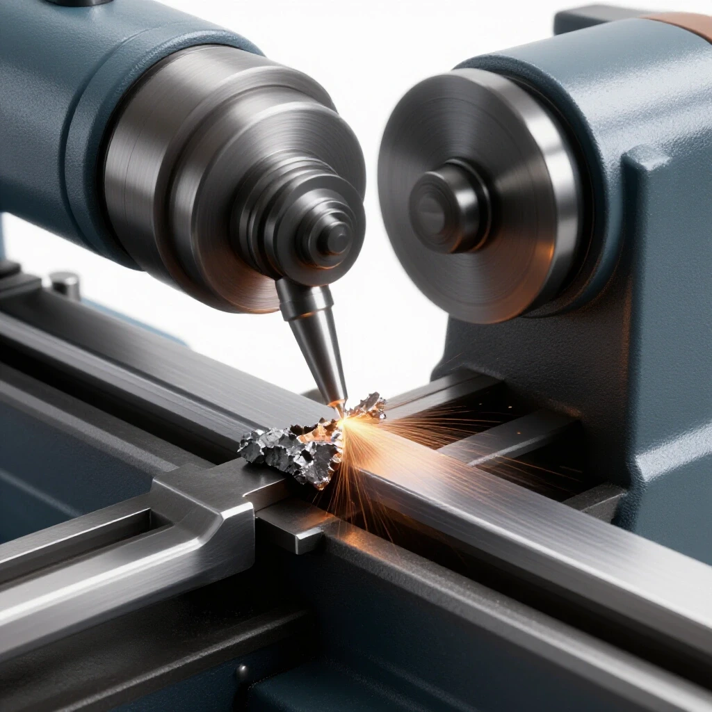
How to Prevent DC Welding Arc Blow on Steel Joints (DIY Fix)
I have spent the better part of eighteen years standing on concrete shop floors, often staring at a weld puddle that refuses to behave. There is a specific kind of frustration that sets in when you have your settings dialed in, your gas flow is steady, and your hand is steady, yet the arc suddenly veers off to the side as if pulled by an invisible magnet. In the world of industrial fabrication, we call this magnetic arc deflection. It is a common hurdle when working with direct current on heavy steel joints, and if you do not have a systematic way to diagnose it, you can waste hours grinding out porous, unstable welds.
My background in millwrighting and machinery repair taught me that most “ghosts in the machine” are actually just physics misbehaving. Whether I am tracking down a harmonic vibration in a lathe spindle or trying to figure out why an arc is wandering at the end of a long fillet weld, the process remains the same. You have to isolate the variables. You cannot just start turning knobs and hope for the best. You need a metalworking diagnostic guide that treats the welding circuit like the electrical system it is.
Understanding the Mechanics of Magnetic Arc Deflection
Magnetic arc deflection occurs when the magnetic field surrounding the welding arc becomes unbalanced, causing the arc to move toward the area of higher flux density. This phenomenon is most common in direct current (DC) welding on ferromagnetic materials like carbon steel.
When you run DC current through a piece of steel, you are essentially creating a temporary electromagnet. The current flows from the electrode, through the arc, into the workpiece, and back to the machine through the work clamp. This flow generates a circular magnetic field. In a perfect world, that field is symmetrical. However, when you get near the end of a plate, or if your ground is placed poorly, the magnetic lines of force get crowded. They take the path of least resistance through the steel, and that “crowding” pushes the arc away from the concentrated field.
In my early days troubleshooting industrial fabrication mills, I saw a crew struggle with a 1-inch thick V-groove butt joint. Every time they reached the last four inches of the seam, the arc would blow backward, leaving a trail of surface porosity and lack of fusion. They thought it was a gas coverage issue, but after checking the flow meter and finding a steady 25 CFH, I realized the magnetic field was simply bunching up at the end of the plate.
Systematic Diagnostic Steps for Unstable Welding Arcs
To solve an arc stability issue, you must follow a structured path of elimination to ensure you are not chasing a phantom problem. This involves checking the physical machine setup before assuming the issue is purely magnetic.
Before diving into complex fixes, I always start with a basic mechanical checklist. You would be surprised how often “arc blow” is actually a loose connection or a contaminated gas line. I use a digital multimeter to check the resistance of the ground path. A healthy circuit should show a resistance value of less than 0.3 Ohms between the work clamp and the workpiece. If the resistance is higher, you have a mechanical contact issue, not a magnetic one.
Isolation of Grounding and Return Path Variables
Isolating the return path involves verifying that the electrical current has a direct, clean route back to the power source without jumping through bearings or hinges. Poor grounding is the primary catalyst for magnetic field imbalances.
If your ground clamp is attached to a table instead of the part itself, you are inviting trouble. The current has to travel through the table, perhaps through a bolt or a pivot point, creating unpredictable magnetic paths. I once diagnosed a tool chatter issue on a large lathe that turned out to be caused by a welder grounding to the machine frame. The stray current was micro-arcing inside the spindle bearings, creating pits that eventually led to resonant vibrations.
- Always place the work clamp as close to the weld zone as possible.
- Ensure the contact point is ground to shiny metal; mill scale adds significant resistance.
- Check that the clamp spring tension is strong enough to maintain a high-pressure connection.
Identifying the Symptoms of Magnetic Interference
Recognizing the difference between a shielding gas problem and magnetic deflection is critical for avoiding unnecessary downtime. Magnetic issues usually present as a directional “push” on the arc.
When you encounter troubleshooting weld porosity, look at the shape of the holes. If they are clustered on one side of the bead and the arc was visibly “blowing” toward that side, you are likely dealing with magnetic deflection. If the porosity is uniform and the arc stayed centered, look at your gas lens or check for a draft in the shop.
| Symptom | Likely Root Cause | Diagnostic Metric |
|---|---|---|
| Arc pulls toward the start of the weld | Back blow (magnetic) | Distance from ground clamp |
| Arc pulls toward the end of the weld | Forward blow (magnetic) | Proximity to edge of plate |
| Uniform porosity in bead | Gas contamination | Flow rate < 15 CFH or leaks |
| Excessive spatter on one side | Directional arc drift | Magnetic flux concentration |
| Intermittent arc snuffing | Loose electrical connection | Resistance > 0.5 Ohms |
Practical Workshop Solutions for Controlling Magnetic Flux
Once you have confirmed that the issue is magnetic, you can use several DIY methods to redirect the flux lines and stabilize the arc. These methods rely on changing the path of the current or the shape of the magnetic field.
One of the most effective metal fabrication fixes I use involves the “grounding split” technique. Instead of using one ground clamp, I use two. By placing one clamp at the start of the weld and one at the end, I balance the magnetic pull. The current now has two paths to return to the machine, which flattens the magnetic field around the arc. This is a standard procedure I recommend for any joint longer than 24 inches.
Using Steel Shunts to Redirect Magnetic Fields
A magnetic shunt is a piece of scrap steel placed across or at the end of a joint to provide a path for the magnetic flux to travel through, preventing it from bunching up at the weld zone.
Think of a shunt like a bypass road for traffic. When the magnetic field hits the end of a plate, it gets “congested.” By tacking a small scrap of steel (roughly the same thickness as your workpiece) at the end of the joint, you extend the path. The magnetic field moves into the scrap piece, allowing you to finish your weld on the actual workpiece with a stable arc. After the weld is complete, you simply snap the scrap piece off and grind the tack smooth.
The Cable Wrap Technique for Field Neutralization
Wrapping the welding lead around the workpiece or a nearby structural member can create a counter-magnetic field that cancels out the arc-deflecting flux.
This is a classic “old school” fix that works surprisingly well. If the arc is blowing to the left, I take the electrode lead and wrap it two or three times around the part in a direction that creates an opposing field. It takes some trial and error to get the direction right. If the blow gets worse, reverse the direction of the wraps. This is an iterative process, much like adjusting the backlash on a mill table; you make a small change, test it, and refine.
Adjusting Technique and Setup for Directional Stability
Sometimes the best way to handle magnetic deflection is to change how you move the torch or how you have prepared the joint. This requires no extra tools, just a change in strategy.
I often tell my students that you cannot fight physics, but you can negotiate with it. If you feel the arc being pushed, you can compensate by “aiming” the electrode into the wind. If the arc is blowing backward, tilt your electrode forward more than usual. This is not a permanent repair for the machine setup, but it is a vital skill for getting a clean bead in a pinch.
Modifying Travel Direction and Sequence
Changing the direction in which you weld relative to the ground clamp can significantly reduce the impact of magnetic pull on the weld puddle.
- Weld toward the ground: If you are experiencing “back blow,” try moving your ground clamp to the end of the joint and weld toward it.
- Back-step welding: Instead of one long continuous bead, break the weld into shorter segments. Start each segment a few inches ahead and weld back toward the previous bead. This redistributes the heat and the magnetic build-up.
- Heavy Tacking: Large, frequent tacks act as mini-shunts. They provide a physical and electrical bridge that helps stabilize the field across the gap.
The Role of Joint Geometry in Arc Stability
The shape of the joint dictates how magnetic flux lines gather. Deep grooves and tight corners are notorious for trapping magnetic fields, which can lead to tool chatter-like inconsistencies in the weld bead.
In a deep V-groove, the magnetic field is forced into a narrow space. This increases the flux density. I have found that increasing the root opening by as little as 0.030 inches can sometimes provide enough “breathing room” for the arc to remain stable. However, you must balance this with the risk of burn-through. In my experience, a consistent root gap of 1/8 inch on 1/2-inch plate is usually the sweet spot for both penetration and arc control.
Diagnostic Math and Measurement Benchmarks
To move from guesswork to professional-grade diagnostics, you need to track your variables. I keep a log of my settings and the resulting arc behavior, much like a machinist tracks feed-per-tooth calculations.
When I am troubleshooting a difficult joint, I use a systematic approach to record my findings. If I change the ground position, I record the distance from the weld. If I wrap the cables, I record the number of turns. This data-driven approach is what separates a fabricator from someone who just “sticks metal together.”
- Arc Length Calibration: Keep your arc as short as possible. A long arc is more susceptible to being pushed by magnetic fields. Aim for an arc length roughly equal to the diameter of your electrode (e.g., 1/8 inch for a 1/8-inch rod).
- Current Verification: Ensure your machine is actually putting out the amperage it claims. I use a clamp-on ammeter to verify that a setting of 125A on the dial is actually 125A at the lead. A 5% variance is common, but anything more indicates an internal machine fault.
- Voltage Drop Testing: Measure the voltage at the machine terminals versus the voltage at the arc. A drop of more than 2 to 3 volts suggests your cables are too long or too thin, which can exacerbate arc instability.
Real-World Case Study: The Heavy Equipment Frame Repair
I once worked on a large excavator frame that had developed a structural crack in a tight corner. The steel was 1.5 inches thick, and the magnetism in the frame was so strong that it would literally pull the rod out of my hand if I wasn’t careful. This was a classic case of residual magnetism in a large mass of steel.
My first attempt resulted in a mess of spatter and lack of fusion. I had to step back and apply the systematic diagnostic steps I have discussed. First, I used a degaussing technique by wrapping the welding leads around the frame and passing a high current through them for a few seconds. Then, I used multiple ground points—four in total—spaced evenly around the repair zone. Finally, I used a short arc technique and welded toward the center of the mass. By isolating the magnetic variables, I was able to produce a code-quality weld on a part that initially seemed “un-weldable.”
Actionable Tracking Framework for Shop Diagnostics
To help you resolve these issues quickly, I have developed a simple fault-tree template. Use this the next time you encounter an arc that won’t stay on track.
- Step 1: Mechanical Check
- Is the ground clamp tight and on clean metal? (Yes/No)
- Is the cable resistance below 0.5 Ohms? (Yes/No)
- Are all connections from the machine to the torch tight? (Yes/No)
- Step 2: Environmental Check
- Is there a draft blowing away the shielding gas? (Yes/No)
- Are you welding near a large motor or transformer? (Yes/No)
- Step 3: Magnetic Isolation
- Does the arc pull toward or away from the ground?
- Does the pull change if you move the ground clamp?
- Does adding a steel shunt at the end of the joint help?
- Step 4: Iterative Fixes
- Try the cable wrap (3 turns).
- Switch to a back-step welding sequence.
- Reduce arc length to the minimum possible.
Conclusion and Next Steps
Mastering the control of magnetic arc deflection is about moving from frustration to observation. When the arc starts to wander, do not fight it with more amperage or faster travel speeds. Stop, look at where your ground is, and think about where those magnetic lines of force are going.
Your first step today should be to inspect your work clamps. Many “magnetic” issues are simply the result of a $20 clamp that has lost its spring tension or is covered in slag. Clean your contact points, move your ground closer to your work, and if the arc still wanders, reach for a scrap piece of steel to use as a shunt. These DIY fixes are the hallmark of a seasoned fabricator who knows how to keep the shop running with minimal downtime.
FAQ: Troubleshooting Magnetic Arc Deflection
Why does my welding arc only start acting up at the very end of a joint? This is known as “end blow.” As you approach the edge of a steel plate, the magnetic field created by the welding current has nowhere to go but to bunch up at the edge. This concentration of magnetic flux pushes the arc back toward the center of the plate. Using a steel “run-out” tab or shunt is the best way to give that flux a path to continue, keeping your arc stable until the very end.
Can I use a permanent magnet to “pull” the arc back into position? I strongly advise against this. While it might seem logical to use a magnet to counter the pull, permanent magnets create their own unpredictable fields that usually make the problem worse. They can also lose their magnetism if they get too hot. It is much better to use electrical methods like cable wrapping or repositioning your ground clamp.
Does the thickness of the steel affect how much the arc wanders? Yes, significantly. Thicker steel can hold a much larger magnetic field. In my experience, you will rarely see these issues on sheet metal thinner than 1/8 inch. However, once you get into 1/2-inch or 1-inch plate, the mass of the steel provides a massive “highway” for magnetic flux, making arc deflection much more likely.
How many wraps of the welding cable should I use for the cable wrap trick? There is no magic number, but I usually start with 3 to 5 wraps. The key is to check the results. If the arc blow gets worse, you are wrapping in the wrong direction. Simply unwrap and wind the cable the other way. It is a trial-and-error process that depends on the specific geometry of your workpiece.
Is it possible for my steel to be “permanently” magnetized before I even start welding? Absolutely. Steel that has been handled by magnetic overhead cranes or has been sitting near large electrical transformers can have residual magnetism. If you suspect this, you can check it by hanging a small piece of steel wire near the joint to see if it is attracted to the plate. If it is, you may need to “degauss” the part by passing an AC current through it or using the cable wrap method with DC.
Does switching from a work clamp to a magnetic ground base help with arc blow? Actually, magnetic ground bases can sometimes contribute to the problem because they introduce a permanent magnetic field into the circuit. While they are convenient, a high-quality, spring-loaded copper clamp is usually better for preventing arc deflection because it does not add any extra magnetic variables to the mix.
What is the difference between “back blow” and “forward blow”? Back blow occurs when the arc is pushed back toward the start of the weld, usually caused by the ground being too close to the start. Forward blow happens when the arc is pushed ahead of the weld pool, often occurring when welding toward a heavy mass of steel or a corner. Knowing which one you have tells you where to move your ground clamp.
Can a dirty liner in my MIG gun cause symptoms that look like arc blow? Yes, and this is a common diagnostic error. A dirty liner or a worn contact tip can cause the wire to feed erratically, which makes the arc jump around. Before you assume it is magnetic, always check your consumables. If the arc “stutters” but stays centered, it is a feed issue. If the arc is smooth but physically leans to one side, it is a magnetic issue.
Will increasing my shielding gas flow help stabilize a wandering arc? No, and it might make it worse. High gas flow (above 35-40 CFH) can create turbulence that makes the arc flutter. If the arc is being moved by magnetism, the gas cannot stop it. Stick to the recommended flow rates—usually 20 to 25 CFH for most shop work—and focus on the electrical and magnetic causes instead.
How does “back-stepping” help with magnetic issues? Back-stepping involves welding in short sections, moving from “clean” metal back into a previously cooled weld bead. This helps because the cooled weld metal acts as a bridge for the magnetic flux, helping to stabilize the field for the next pass. It also helps manage heat distortion, which is a nice secondary benefit.
(This article was written by one of our staff writers, Paul Whitaker. Visit our Meet the Team page to learn more about the author and their expertise.)