How to Read and Use Digital Calipers Accurately (Easy Guide)
In my fourteen years on the shop floor, I have seen how a single misplaced decimal point can turn a structural project into a safety hazard. I remember inspecting a heavy-duty equipment trailer frame that had cracked along a primary load-bearing gusset. The failure wasn’t due to poor welding technique alone, but rather a structural gap caused by an inaccurate measurement during the layout phase. The fabricator had relied on a loose measurement, leading to a 0.040-inch gap that was “bridged” with weld metal. This created a massive heat-affected zone (HAZ) that eventually succumbed to fatigue.
When we work with metal, we are managing physical forces that do not forgive. Whether you are building a custom roll cage or a simple workbench, the structural integrity of your project depends on how well the components fit together. Precision measurement is the first line of defense against structural failure. Using electronic linear measuring tools correctly allows us to identify potential fit-up issues before we ever strike an arc. By mastering these devices, you can ensure that your structural metal load capacity remains within safe limits and that your joints are prepared to handle the stresses of real-world use.
The Role of Precise Measurement in Structural Safety
Precision in fabrication refers to the ability to match design specifications within a defined tolerance. In structural metalwork, even small deviations can lead to uneven load distribution, causing stress concentrations that might exceed the yield strength of the material and result in catastrophic failure. Accuracy ensures that every component shares the load as intended by the design.
Understanding Tolerance and Material Stress Thresholds
Tolerance is the allowable limit of variation in a physical dimension. In garage fabrication safety, staying within these limits is vital because excessive gaps in a joint require more weld filler, which increases the heat input. High heat can weaken the heat-affected zone weakness, making the steel brittle and prone to cracking under a heavy load or sudden impact.
When I analyze material stress thresholds, I look at the yield strength, which is the point where metal permanently deforms. If a structural member is cut too short, the resulting weld joint may not have the required cross-sectional area to support the weight. For example, a 1/4-inch plate of A36 steel has a yield strength of about 36,000 PSI. If your measurement error leads to a poor fit, you might reduce the effective strength of that joint by 20% or more.
How Fit-Up Accuracy Prevents Welding Defects
Welding defect troubleshooting often begins with looking at the initial fit-up of the parts. If your pieces are not measured and cut with high precision, you will likely encounter issues like burn-through or lack of fusion. Using electronic tools to verify that your gaps are consistent helps maintain a stable welding gas flow rate and ensures the arc stays focused on the root of the joint.
Poorly fitted joints are the primary cause of warping and distortion. When you have a large gap on one side of a frame, the weld metal shrinks as it cools, pulling the entire structure out of alignment. By using electronic linear tools to keep your tolerances within 0.005 to 0.010 inches, you minimize the amount of filler metal needed. This keeps your heat input low and your structure straight and predictable.
Mastering Electronic Linear Measurement Procedures
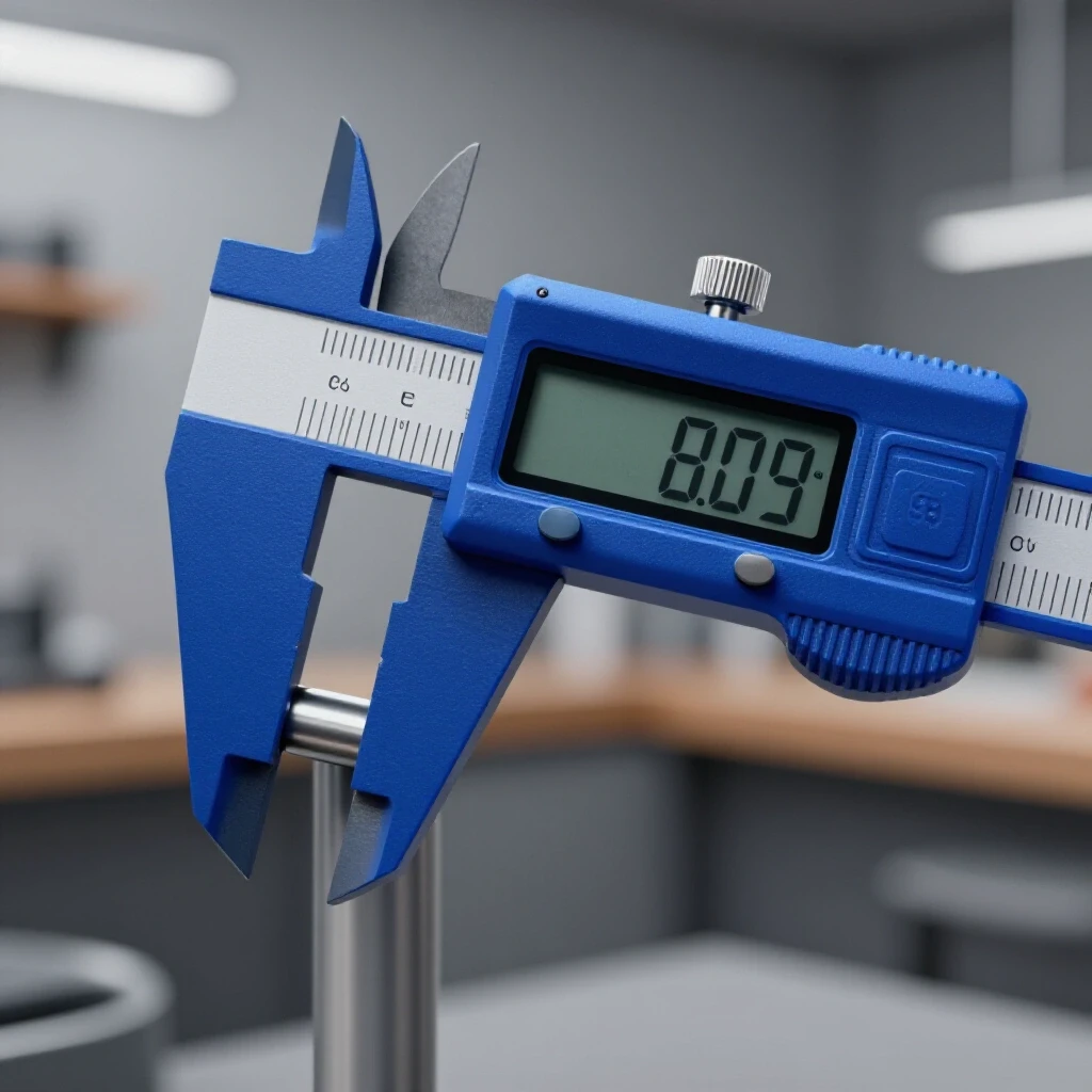
Electronic linear measuring tools are the standard for modern workshop accuracy, providing digital readouts of external, internal, and depth dimensions. These tools use a capacitive sensor to track the movement of the sliding jaw, translating physical distance into a readable number on an LCD screen. They are essential for verifying material thickness and hole diameters.
Establishing a Reliable Baseline with Zeroing
Zeroing is the process of telling your measuring tool where the “starting point” is by closing the jaws and pressing the zero button. This ensures that the electronic sensor is synchronized with the physical position of the jaws. Without a proper zero, every subsequent measurement you take will be offset by a consistent error, leading to failed layouts.
Before I start any layout, I wipe the measuring faces of the jaws with a clean, lint-free cloth. Even a tiny speck of dust can throw off the zero by 0.001 inches. I close the jaws with light, consistent pressure and check that the display reads 0.000. If it doesn’t, I press the zero button. I repeat this check several times throughout a project to ensure the tool hasn’t drifted due to temperature changes or handled vibrations.
Optimizing Jaw Contact for Accurate External Readings
To get an accurate reading on the outside of a workpiece, the jaws must be perfectly square and flat against the material surface. If the tool is tilted or if you use the very tips of the jaws, the measurement will likely be larger than the actual dimension. This is known as “Abbe error,” where a small angular misalignment is magnified over the distance of the measurement.
I always try to seat the workpiece as far back into the jaws as possible, near the main beam of the tool. This is where the jaws are most rigid and less likely to flex. I apply just enough pressure to make solid contact. If you squeeze the jaws too hard, you can actually compress the material or flex the tool, giving you a false reading that could ruin a high-precision structural joint.
Verifying Internal Dimensions and Depth for Load Paths
Measuring the inside of a tube or the depth of a hole requires using the smaller, top-mounted jaws or the depth rod at the end of the tool. For internal measurements, you must ensure the jaws are parallel to the diameter you are checking. For depth, the base of the tool must be held perfectly flat against the reference surface to prevent the rod from entering at an angle.
In structural design, the depth of a bolt hole or the internal diameter of a sleeve is critical for load shear paths. If a sleeve is too large, the bolt will vibrate, leading to “fretting” and eventual bolt failure. I use the internal jaws to check that my tolerances for press-fit or slip-fit components are within the 0.001 to 0.003-inch range required for mechanical stability.
Managing Environmental Factors in Metal Fabrication
The workshop environment is often filled with variables that can interfere with precision, such as temperature swings, metal dust, and oily residues. Maintaining a clean workspace and understanding how these factors affect your tools is a key part of any workshop safety checklist. Protecting your instruments ensures your structural data remains valid and reliable.
Neutralizing the Impact of Debris and Mill Scale
Mill scale is the flaky, dark coating found on hot-rolled steel, and it is a major enemy of accuracy. If you measure over mill scale, you are measuring the thickness of the oxide layer, not the actual steel. This can lead to errors of up to 0.005 inches, which is enough to cause a poor fit in a critical structural assembly.
I always grind or sand the area I am measuring down to bright, clean metal. This ensures the jaws of the electronic tool are contacting the actual structural material. Similarly, metal shavings or “swarf” from drilling can get trapped between the jaws and the beam. If you feel any grittiness when sliding the tool, stop immediately and clean it, as debris can scratch the internal sensor and cause permanent damage.
Preventing Misalignment During High-Stakes Layouts
Misalignment occurs when the measuring tool is not held perpendicular to the axis of the part. In garage fabrication safety, this often happens when trying to measure large plates or long tubes alone. If the tool is canted even slightly, the resulting measurement will be longer than the true distance, leading to parts that are too large to fit into their designated slots.
To prevent this, I often use a “rocking” motion when measuring diameters. I move the tool slightly back and forth while closing the jaws until I find the smallest possible reading. That smallest reading is the true diameter. For flat parts, I use a square to ensure the tool is positioned correctly. Consistent technique is the only way to get repeatable data that you can trust for structural load calculations.
| Measurement Error Source | Structural Consequence | Preventive Action |
|---|---|---|
| Debris on Jaws | Incorrect fit-up, leading to large weld gaps | Wipe jaws with a clean cloth before every use |
| Excessive Jaw Pressure | False small readings, causing parts to be too tight | Use consistent, light thumb pressure on the slider |
| Measuring over Mill Scale | Inaccurate material thickness data | Clean metal to a bright finish before measuring |
| Angular Misalignment | Parts cut too long, causing frame distortion | Ensure jaws are square to the workpiece surface |
| Un-zeroed Tool | Consistent offset error in all dimensions | Zero the tool against closed, clean jaws frequently |
Integrating Precision into Your Workshop Safety Checklist
A workshop safety checklist should include more than just PPE; it should cover the verification of every measurement that affects structural integrity. Before I begin any welding, I perform a “dry fit” and use my electronic tools to verify every critical dimension. This practice identifies errors while they are still easy to fix, preventing the wasted material and frustration of a failed build.
Unit Switching and Conversion for Structural Load Calculations
Most electronic measuring tools allow you to switch between inches and millimeters with the press of a button. This is incredibly useful when working with international designs or specialized hardware. However, you must be careful to verify which unit you are currently using. Mixing up 10mm and 10/16ths of an inch is a recipe for a structural disaster.
I always double-check the screen icon to confirm the units before recording a measurement. When I perform structural load calculations, I prefer to work in decimal inches or millimeters rather than fractions. Fractions are difficult to use in formulas for PSI or stress analysis. By using the decimal output from a digital tool, I can plug the numbers directly into my engineering spreadsheets without the risk of a conversion error.
Using Step Measurements for Consistent Tab Alignment
The “step” measurement is a less common but vital function where you use the back of the tool to measure the distance between two offset surfaces. This is perfect for ensuring that mounting tabs or brackets are aligned perfectly on a frame. If your tabs are not aligned, the bolts will be under constant shear stress, which can lead to a sudden fracture.
To use the step function, I place the stationary head of the tool on the higher surface and slide the moving jaw down until it touches the lower surface. This gives me a direct reading of the offset. In my workshop, I use this to ensure that engine mounts or suspension pick-up points are symmetrical within 0.010 inches. This level of precision is what separates a safe, professional fabrication from a dangerous “backyard” project.
Advanced Structural Verification and Inspection
Once a project moves from layout to welding, the role of measurement shifts to inspection. I use my electronic tools to monitor for heat-induced warping. By measuring the distance between two points before and after welding, I can see exactly how much the metal has pulled. This data helps me adjust my welding sequence to keep the structure within safety margins.
Monitoring Heat-Affected Zone (HAZ) Distortion
Every time you apply heat to metal, it wants to move. The heat-affected zone weakness is where the metal has been heated enough to change its properties but not enough to melt. This area is prone to shrinking, which can pull a perfectly measured frame out of square. I use my measuring tools to check for “pull” after every few inches of weld.
If I notice a dimension shrinking more than 0.015 inches, I stop and change my welding direction. This is a key part of welding defect troubleshooting. By monitoring the physical dimensions of the project in real-time, you can counteract the forces of thermal expansion and contraction. This ensures that the final structure remains true to the original design and maintains its intended load-bearing capacity.
Implementing a Structural Joint Verification Checklist
Before I sign off on a project, I go through a final verification list. This isn’t just about making sure it looks good; it’s about verifying that the math matches the metal. I use my electronic linear tools to check the final dimensions against my blueprints one last time.
- Verify all critical hole diameters for bolt clearance (0.010″ to 0.030″ over bolt size).
- Check the thickness of all structural plates to ensure they match the design specs.
- Measure the “out-of-round” on any tubing that was bent or welded.
- Confirm that parallel members are within 0.020″ of each other over their entire length.
- Check the depth of all blind holes to ensure full thread engagement for fasteners.
- Verify that all mounting surfaces are flat and not warped by welding heat.
Practical Benchmarks for Safe Fabrication
When you are working in a home shop, it can be hard to know what “good enough” looks like. In my experience, setting specific benchmarks for your measurements helps remove the guesswork. For most structural steel projects, a tolerance of +/- 1/32 inch (0.031″) is standard for overall length, but for joint fit-up, you should aim for +/- 0.010 inch.
- Joint Gap: Aim for a gap no larger than 0.010 inches for TIG welding and 0.030 inches for MIG.
- Material Thickness: Always verify with your digital tool; “1/4 inch” plate can vary by 0.010″ or more depending on the supplier.
- Bolt Holes: Keep tolerances tight to prevent shock loading on the fasteners.
- Squareness: Use the “3-4-5” rule or diagonal measurements, verified with your electronic tool for smaller components.
By sticking to these benchmarks, you ensure that your structural metal load capacity is based on solid geometry rather than hope. A well-measured project is a safe project. Taking the extra thirty seconds to clean your metal, zero your tool, and check your jaw contact is the best insurance policy you can have in the workshop.
In the end, the tools we use are only as good as our commitment to accuracy. I have seen talented welders fail because they were lazy with their layout. On the other hand, I have seen beginners produce professional-grade work because they respected the numbers. Precision is a habit. If you make it a part of your daily routine, you will find that your projects fit together better, your welds are stronger, and your workshop is a much safer place to be.
FAQ: Precision Measurement in Metal Fabrication
How do I know if my electronic measuring tool is giving me a false reading? The most common sign of a false reading is “non-repeatability.” If you measure the same part three times and get three different numbers, something is wrong. Usually, this is due to debris on the jaws, uneven pressure, or the tool needing to be re-zeroed. Always check your zero after a questionable reading to see if the tool returns to 0.000.
Why does the display on my tool flicker or show random numbers? This is often caused by electromagnetic interference (EMI) from a welder or a low battery. If you are welding nearby, the high-frequency start of a TIG welder can scramble the electronic sensor. Move the tool away from the welding area or replace the battery if the display becomes unstable.
Can I use an electronic measuring tool on hot metal? No. Heat causes metal to expand, which will give you an inaccurate reading. Furthermore, the electronic sensors and the plastic housing of the tool can be damaged by temperatures above 140°F (60°C). Always wait for your workpiece to cool to room temperature before taking a final measurement.
How much pressure should I apply when closing the jaws? You should apply “light, consistent pressure.” A good rule of thumb is to use the same amount of force you would use to hold a business card against a wall without dropping it. Many tools have a “thumb roller” designed to help you apply consistent pressure every time.
What is the best way to measure a round tube? To measure a tube’s outer diameter, place it between the main jaws and slowly “rock” the tool back and forth across the diameter. The lowest number that appears on the screen as you pass through the center point is the true diameter.
Does it matter if I measure with the tips of the jaws? Yes, it matters. The tips of the jaws are the most likely to flex, which can lead to a larger-than-actual reading. Whenever possible, place the workpiece as deep into the jaws as it will go, near the solid beam of the tool, for maximum accuracy.
How often should I zero my tool? I recommend zeroing the tool at the start of every work session and any time you switch between different types of measurements (like moving from external to internal). If the ambient temperature in your shop changes significantly, re-zero the tool to account for the thermal expansion of the tool’s own metal beam.
What should I do if my tool gets wet or covered in coolant? Wipe it down immediately with a dry, clean cloth. Most basic electronic tools are not waterproof. If liquid gets into the electronics, it can cause a short circuit. Some higher-end models have an “IP” rating (like IP67) which means they are resistant to dust and water, but it is still best practice to keep them dry.
Can I use the depth rod as a scribe to mark my metal? Absolutely not. The depth rod is a precision measuring surface, not a marking tool. Using it to scratch metal will dull the end and change its length, making all future depth measurements inaccurate. Use a dedicated carbide scribe or a layout dye for marking.
How do I measure the thickness of a weld bead? While you can use the jaws to get a rough idea, it is difficult to get an accurate reading on a curved weld surface. For structural inspection, pros use a dedicated “weld fillet gauge.” However, you can use the depth rod of your electronic tool to measure the “throat” of the weld if you have a flat reference point nearby.
(This article was written by one of our staff writers, James Harlan. Visit our Meet the Team page to learn more about the author and their expertise.)