Simple In-Process Quality Checks for Custom Welding (DIY Fix)
Scaling a fabrication shop is rarely a smooth path. I remember the exact moment I realized my home-based operation had outgrown its “hobby” roots. I was tripping over a pile of offcuts while trying to reach a vibrating 220V air compressor, all while the smoke from a long MIG session made it nearly impossible to see the end of the bead. I was producing more than ever, but my rework rate was climbing. My layout was a mess, my power was maxed out, and I was missing simple errors because I couldn’t see them through the haze or find my measuring tools in the clutter.
Twenty years later, my shop looks very different. The transition from a basic setup to a semi-professional manufacturing space isn’t just about buying bigger machines; it is about engineering a system where quality is easy to maintain. When you move into CNC integration and high-volume output, the physical bottlenecks of your shop floor become your biggest enemy. If you have to walk across the room to grab a straightedge, you probably won’t check that part for warping. If your lighting is poor, you won’t notice the tiny pinholes in your weld until the part is at the powder coater.
This guide is about the strategic redesign of your workspace to support high-level output. We will look at how material flow, electrical stability, and air management create an environment where you can spot defects the moment they happen. By applying lean principles to a small-scale shop, we can reduce the friction that leads to costly mistakes.
Mapping Material Travel to Catch Errors Early
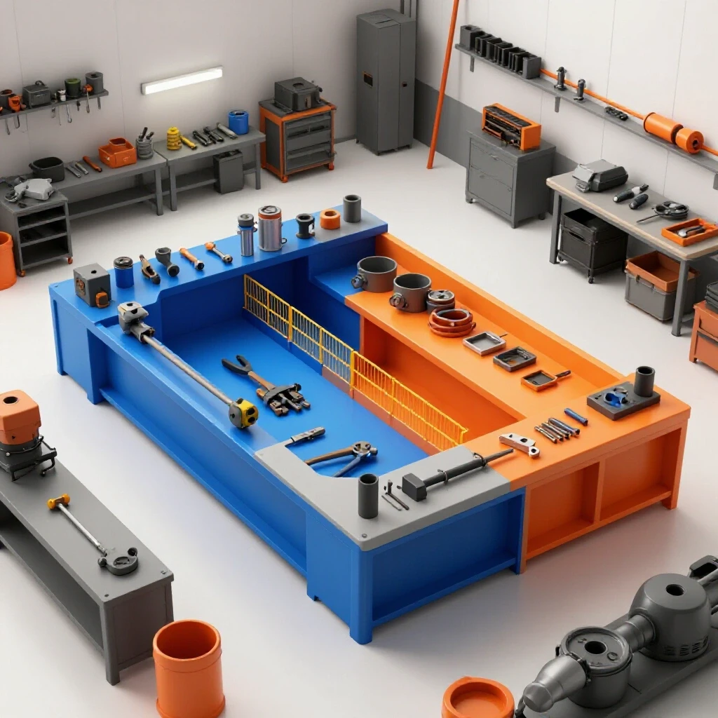
Material flow is the physical path a piece of steel takes from the moment it enters your shop as a raw tube or sheet until it leaves as a finished product. In an optimized shop, this path should be as close to a straight line or a logical “U” shape as possible to minimize handling and keep your eyes on the work.
When you are constantly moving heavy parts back and forth across a cramped floor, you lose the mental bandwidth needed for quality control. Fatigue leads to a “good enough” mindset. By zoning your shop, you ensure that the tools needed for visual and tactile checks are always within arm’s reach of the workstation. This reduces the physical barrier to performing a quick verification between passes.
Why Back-and-Forth Foot Traffic Kills Shop Throughput
Excessive movement is a form of “waste” in lean manufacturing that directly impacts your ability to monitor work quality. When a fabricator spends 15% of their day just walking to get tools or move material, their focus on the technical details of the weld or the cut begins to slip.
I once tracked my steps during a bumper build. I walked nearly two miles inside a 1,000-square-foot shop. By reorganizing my welding table to be central to my material rack and my hand tools, I cut that movement by 60%. More importantly, I found that I was more likely to grab my flashlight and check for undercut because the light was right there, not buried under a pile of scrap across the room.
Workshop Layout Flow Comparison
| Layout Type | Description | Best For | Impact on Quality Monitoring |
|---|---|---|---|
| Spaghetti Flow | Tools and machines placed wherever they fit. | Beginners / Small hobby shops | High risk of missed defects due to clutter and fatigue. |
| Straight-Line Flow | Raw material in one end, finished product out the other. | Long, narrow shops | Excellent; allows for inspection stations between phases. |
| U-Shape Cell | Material enters and exits on the same side; machines wrap around. | High-output micro-manufacturing | Best; keeps the fabricator in a central hub with all tools. |
| Zoned Layout | Grouping by process (Cutting, Welding, Grinding). | Multi-person shops | Good; requires dedicated inspection areas in each zone. |
Establishing Machine Spacing Boundaries
A common mistake in scaling up is crowding machines. For a safe and efficient workflow, you need a 3-foot minimum access zone around every major piece of equipment. This isn’t just for safety; it is so you can physically get around the part to inspect it from all angles. If a weldment is pushed up against a wall, you can’t see the back side of the joint, which is often where the most significant flaws hide.
Scaling Electrical Infrastructure for Consistent Arc Performance
A stable electrical supply is the foundation of high-quality fabrication. If your voltage sags when the neighbor’s AC kicks in, or when your CNC plasma table fires up, your weld penetration will vary. This inconsistency makes it much harder to perform reliable visual checks because the machine’s behavior is a moving target.
For many of us, the jump to 3-phase power is the “line in the sand” between a hobby shop and a professional operation. While most residential areas only offer single-phase power, we can use converters to run industrial-grade equipment. This allows for smoother arcs and more reliable motor performance on your larger tools.
Understanding 3-Phase Power Converters
A 3-phase power converter takes your standard 240V single-phase input and creates a third “leg” of power. This is necessary for running industrial lathes, mills, and high-end welders that require a more balanced electrical load. There are three main ways to achieve this in a home-based shop.
- Static Converters: These are the cheapest but only provide 3-phase power during startup. The motor will only run at about 2/3 of its rated horsepower. I don’t recommend these for high-precision work.
- Rotary Phase Converters (RPC): These use a physical 3-phase motor (an idler) to generate the third leg. They are reliable and can power multiple machines, but they are noisy and consume power even when you aren’t cutting.
- Digital Phase Converters: These use solid-state electronics to create perfect 3-phase power. They are quiet and highly efficient, but they come with a high capital cost.
3-Phase Converter Options and Amortization
| Converter Type | Initial Cost | Efficiency | Power Quality | Lifespan |
|---|---|---|---|---|
| Static | $100 – $300 | Low | Poor | 5-10 Years |
| Rotary (RPC) | $600 – $2,000 | Medium | Good | 20+ Years |
| Digital | $2,500 – $5,000 | High | Excellent | 15+ Years |
Managing Electrical Phase Loads
When you install a rotary converter, you must balance the voltage across all three legs. If one leg is significantly higher or lower, your equipment can overheat or perform poorly. I suggest using a “phase balancing log” to check your voltages under load once a month. A balance within 5% is usually acceptable for most fabrication equipment. When your power is balanced, your welder produces a consistent bead, which means your visual spot-checks will be looking for technique errors rather than equipment failures.
Designing High-Volume Air Filtration for Visual Clarity
You cannot inspect what you cannot see. In a high-output shop, weld fumes and grinding dust build up rapidly. This haze doesn’t just hurt your lungs; it coats your workspace in a fine layer of gray dust that hides surface defects like porosity or cold lap.
A professional-grade air management system involves two parts: source capture and ambient filtration. Source capture uses “fume arms” or downdraft tables to suck away smoke the moment it is created. Ambient filtration uses “air scrubbers” to clean the air that escapes the source capture.
CFM Airflow Metrics for Shop Tools
To design an effective system, you need to understand Cubic Feet per Minute (CFM). This is the volume of air your fan can move. However, you also have to account for static pressure—the resistance created by the ducts and filters.
- CNC Plasma Tables: Require 1,000–2,000 CFM depending on table size.
- Welding Stations: Require 500–800 CFM per person for effective source capture.
- Grinding Booths: Require 1,200+ CFM to pull heavy metallic dust.
Duct Collection Design and Static Pressure Losses
When I built my first duct network, I used 4-inch PVC because it was cheap. It was a disaster. The static pressure loss was so high that my 1,200 CFM collector was only pulling about 400 CFM at the tool. I learned that for metalworking, you need smooth-walled metal ducting, ideally 6 inches or larger for main lines.
Keep your duct runs as short as possible and use “long-radius” elbows instead of T-junctions. Every 90-degree turn is equivalent to adding several feet of straight pipe in terms of air resistance. If your air is clear, your eyes stay sharp, and those simple visual checks become a natural part of your workflow.
Integrating CNC Plasma Systems Without Sacrificing Manual Oversight
Integrating a CNC plasma table is a massive step in shop evolution. It moves you from manual cutting to automated production. However, automation can create a false sense of security. Just because a computer cut the part doesn’t mean the part is perfect.
The “learning curve” of CNC isn’t just about the software; it’s about understanding how to inspect the output. You have to watch for dross (hardened slag), bevel (the angle of the cut), and piercing errors. If your air supply to the plasma cutter has moisture, your cut quality will plummet, and your parts won’t fit together correctly during welding.
Software CAD/CAM Integration and Tooling Files
Your workflow starts in the digital world. Using a “tool library” in your CAM software allows you to save the exact settings for different thicknesses of mild steel. This consistency is a form of quality control. If you use the same “cut chart” every time, you know exactly what a “good” cut should look like.
- CAD (Computer-Aided Design): Where you draw the part.
- CAM (Computer-Aided Manufacturing): Where you tell the machine how to cut it (lead-ins, speeds, and torch height).
- Post-Processor: The “translator” that turns CAM into G-code the machine understands.
Leveling and Squaring the Gantry
A CNC table that is 1/16th of an inch out of square over four feet might not seem like much, but it will cause major headaches during assembly. I use a “tramming” procedure every month to ensure the gantry is perfectly perpendicular to the rails. A quick check with a precision square on a test-cut piece of scrap is a simple way to verify that your automation is still performing as intended.
Simple Routine Monitoring During the Build
Now that the shop layout, power, and air are optimized, we focus on the actual act of checking the work. These are the low-tech, high-impact steps you take while the steel is still on the bench. You don’t need expensive lab equipment; you need a flashlight, a straightedge, and a file.
These checks are “in-process,” meaning you do them between passes or before moving to the next assembly step. This prevents a small error from being buried under more metal, which would require an angle grinder and an hour of rework to fix later.
The Flashlight and Straightedge Method
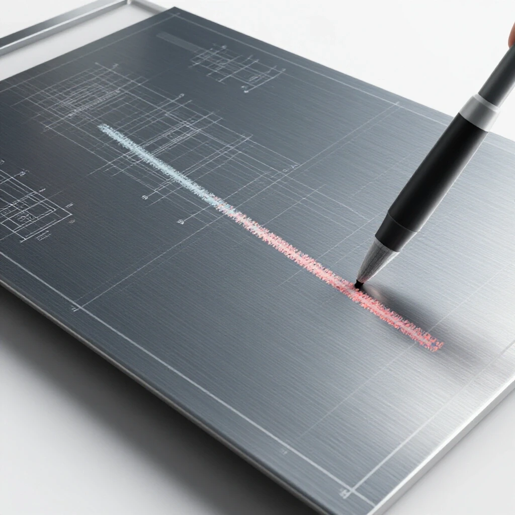
A high-lumen LED flashlight is perhaps the most important quality tool in my shop. By shining the light at a low angle across the weld bead, you can highlight “undercut”—a groove melted into the base metal that hasn’t been filled. You can also spot “porosity,” which looks like tiny bubbles or holes in the metal.
A straightedge is used to check for heat distortion. As you weld, the metal expands and contracts. If you lay down too much heat too fast, the part will warp. By laying a straightedge across the joint after each tack or pass, you can see if the metal is pulling out of alignment. If it is, you can stop and adjust your welding sequence to pull it back.
Using a File for Tactile Verification
Sometimes your eyes can deceive you, especially with shiny mild steel. A simple mill file can tell you a lot about the quality of a joint. If the file “skips” or feels like it’s hitting a glass-like surface, you might have “slag inclusions” or a very hard, brittle spot in the weld. If the file bites in smoothly, you know the metal is consistent.
I also use a file to quickly check for “high spots” or “cold lap,” where the weld metal is just sitting on top of the base metal without actually fusing. If the file can easily get under the edge of the bead, you have a fusion problem.
Actionable Checkpoints for Manual Inspection
- Pre-Weld: Check fit-up gaps. If the gap is wider than your wire diameter, you’re headed for trouble.
- After Tacking: Use a square or straightedge. If it’s not straight now, it won’t be straight after the full weld.
- Mid-Pass: Stop and use the flashlight. Look for “silica islands” or brown spots that might hide a pinhole.
- Post-Weld: Use the file to remove any berries or spatter. This allows you to see the “toe” of the weld clearly.
Workshop Layout Matrix for Scaling Operations
| Feature | Hobby Setup (Current) | Semi-Pro Evolution (Goal) | Why It Matters |
|---|---|---|---|
| Material Handling | Hand-carrying sheets | Jib crane or sheet cart | Reduces fatigue and prevents surface scratches. |
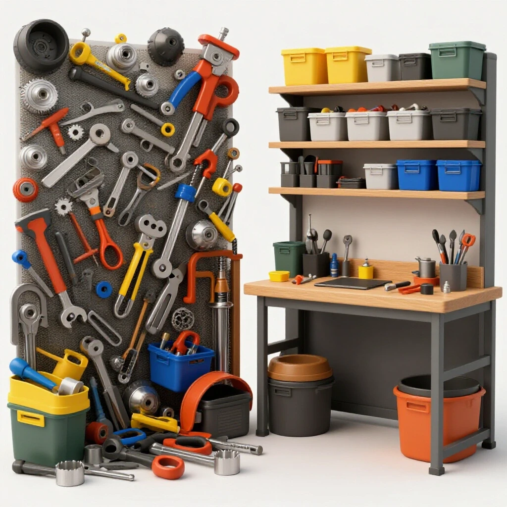
| Tool Accessibility | Tools in a central chest | Point-of-use tool boards | Keeps inspection tools within reach of the weld table. |
| Lighting | Overhead shop lights | Dedicated task lighting at 100+ foot-candles | Essential for spotting surface porosity. |
| Part Cleaning | Wire brush by hand | Dedicated abrasive blast or chemical dip | Ensures a clean surface for better visual monitoring. |
Conclusion: Building a System That Supports Quality
Transitioning your shop from a hobby space to a semi-professional operation is a marathon, not a sprint. It requires a shift in how you view your floor space and your equipment. By focusing on a linear material flow, you reduce the physical stress that leads to skipped steps. By investing in stable 3-phase power and high-volume air filtration, you create an environment where your machines—and your eyes—can perform at their best.
The most sophisticated CNC plasma table in the world cannot replace the intuition of an experienced fabricator. The goal of these shop upgrades is to get the “noise” out of the way. When the air is clear, the power is steady, and your tools are exactly where they should be, you can focus on the work itself. Those simple checks with a flashlight and a file become effortless habits rather than chores.
Start by looking at your floor plan. Where are you walking the most? Move those tools closer. Next, look at your air. If you can smell the weld smoke ten minutes after you stop, your filtration needs an upgrade. These incremental changes build the foundation for a shop that doesn’t just produce more, but produces better.
FAQ: Optimizing Your Fabrication Shop
How do I know if my shop layout is causing bottlenecks? If you find yourself moving the same piece of material more than three times to complete a process, or if you are constantly “shuffling” tools to make room to work, your layout is a bottleneck. Try drawing a “spaghetti diagram” of your movements during a typical build to see where the waste is.
Can I run a CNC plasma table on a rotary phase converter? Yes, but you must ensure the converter is sized correctly. CNC electronics are sensitive to voltage fluctuations. A digital phase converter is often a better choice for CNC equipment, but a well-balanced rotary converter can work if it has enough capacity (usually double the HP of the machine’s load).
What is the “10-foot rule” for shop tools? The 10-foot rule suggests that the tools you use most frequently (like your flashlight, squares, and files) should be within 10 feet of your primary workstation. This reduces the “activation energy” required to perform a quick check on your work.
How often should I clean my air filtration filters? In a high-output shop, pre-filters should be checked weekly and replaced or cleaned monthly. Main HEPA or cartridge filters should be monitored using a “magnehelic gauge” which measures the pressure drop. When the pressure drop increases significantly, the filters are clogged.
Why is moisture in my air lines a problem for CNC cutting? Moisture causes the plasma arc to become unstable and rapidly wears out your consumables (nozzles and electrodes). This leads to poor cut quality, excessive dross, and parts that don’t fit together well, making your welding process much more difficult.
What is the best way to spot warping before it’s too late? Use a straightedge after every few inches of welding. If you see a gap forming between the straightedge and the metal, stop immediately. You may need to use “clamping heat sinks” or change your welding pattern to the “backstep” method to counteract the pull.
Do I really need 3-phase power for a small shop? You don’t need it for basic work, but as you scale up to larger motors (5HP and above) or high-end industrial welders, 3-phase becomes much more efficient. It allows for smaller wire sizes in your walls and provides much smoother power delivery for high-precision tools.
How much space do I need around my welding table? Ideally, you want at least 3 to 5 feet of clear space on all sides. This allows you to move freely, use a cart to bring in parts, and—most importantly—view your work from different angles to ensure everything is square and the beads are consistent.
What is “static pressure” in a dust collection system? Static pressure is the resistance the air faces as it moves through your ducts. It’s caused by friction against the pipe walls and turbulence in bends. If your static pressure is too high, your fan won’t be able to pull enough air to keep the shop clear of smoke and dust.
How do I balance the legs on my rotary phase converter? You use a multimeter to measure the voltage between each pair of legs (L1-L2, L2-L3, and L1-L3) while the converter is running under a typical load. You can then add or remove “run capacitors” to the circuit to bring the voltages closer together, aiming for less than a 5% difference.
(This article was written by one of our staff writers, Edward Sinclair. Visit our Meet the Team page to learn more about the author and their expertise.)