Essential Pre-Paint Inspection Steps for Welded Parts (Guide)
Scaling a fabrication shop from a personal hobby into a professional-grade operation is a journey of managing chaos. In my 20 years of running a shop, I have learned that the most expensive mistakes do not happen during the weld itself. They happen in the moments before a part is sent off for its final finish. When you transition to high-output manufacturing, you realize that a beautiful weld can hide a structural flaw, or a tiny bead of spatter can ruin a high-dollar powder coat.
My background in manufacturing operations taught me that efficiency is not just about moving fast. It is about reducing the “rework loop.” If a part reaches the paint booth and then gets rejected because of a surface defect, you have lost the labor time of the welder, the material handler, and the inspector. I have spent years refining my layout and systems to catch these issues early. This guide focuses on the critical physical and technical checks required to ensure your welded assemblies are truly ready for their final coating.
Optimizing Shop Layout for Systematic Part Verification
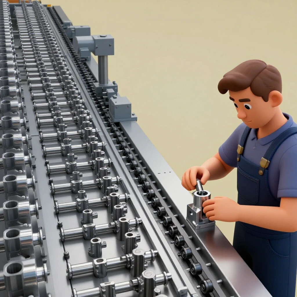
Workshop layout mapping is the process of designing a logical path for materials to move from the welding bench to the final assessment zone. A well-planned flow ensures that every surface of a component is accessible for review without creating bottlenecks in the middle of the shop floor.
In my early days, I had a “back-and-forth” workflow. I would weld a part, walk it across the shop to a bench for cleaning, and then realize the lighting was too poor to see the underside. I’d have to move it again. Now, I advocate for a linear flow. Your parts should move in one direction: from the CNC plasma table to the welding station, then directly into a dedicated cleaning and inspection bay.
A dedicated inspection bay should have at least three feet of clearance on all sides of the part. This “access zone” allows you to walk around the assembly with a light source, checking for slag or undercut from every angle. If you are cramped against a wall, you will miss defects on the back side of the part.
| Layout Feature | Hobby Setup (Random Flow) | Professional Setup (Linear Flow) |
|---|---|---|
| Material Path | Circular/Overlapping | Straight line/U-shaped |
| Inspection Zone | Shared with welding table | Dedicated, clean area |
| Lighting | Standard overhead shop lights | High-intensity task lighting (1000+ LUX) |
| Handling | Manual lifting | Jib cranes or roller tables |
Electrical Infrastructure for Surface Refinement
Designing a robust electrical system means providing the necessary power for industrial-grade grinders, sanders, and high-intensity lighting used during the final cleanup of a part. A steady power supply prevents tool stall and ensures that surface finishing is consistent across the entire project.
When I upgraded to a 3-phase power converter, the performance of my finishing tools changed overnight. Most industrial grinders run smoother on 3-phase power, which reduces operator fatigue and leads to a more uniform surface. If you are running a rotary phase converter, you need to balance the voltage across all three legs. An unbalanced load can cause tools to overheat, leading to “chatter marks” on the metal surface that show up clearly after painting.
Proper lighting is also an electrical concern. I recommend a dedicated circuit for LED task lighting in your verification zone. You need to see the “profile” of the weld. If the light is too dim, you won’t notice the tiny pinholes or “porosity” that can trap moisture and cause the paint to bubble later.
- Rotary Phase Converters: Best for high-surge loads like large grinders.
- Static Converters: Cheap but only provide about 2/3 of the motor’s rated power.
- Variable Frequency Drives (VFDs): Excellent for controlling speed on sanders but require one unit per tool.
High-Volume Air Filtration and Dust Management
Air quality management involves using industrial-grade filtration to remove the fine metallic dust and slag particles generated during the final smoothing of a weld. Keeping the air clean is vital because airborne dust can settle back onto a cleaned part, preventing the paint from adhering correctly.
In my shop, I learned the hard way that a shop vac is not a dust collection system. When you are grinding down weld reinforcements or removing spatter, you create a massive amount of “heavy” dust. You need a system that can handle at least 1,000 to 2,000 CFM (Cubic Feet per Minute) to effectively pull that dust away from the work surface.
I use a multi-stage cyclone separator. The cyclone drops the heavy sparks and large metal chunks into a bin, while the fine filters catch the microscopic dust. This prevents the filters from clogging every twenty minutes. If your air filtration is poor, you are essentially trying to inspect a part through a fog of grit.
- 1,000 CFM: Minimum for a single-operator grinding station.
- 2,000 CFM: Ideal for a two-person shop or large-scale sanding.
- Duct Velocity: Aim for 4,000 feet per minute (fpm) in the ducts to keep metal dust from settling and creating a fire hazard.
Visual Assessment of Surface Integrity and Joint Continuity
Surface assessment is the manual and visual process of checking a welded joint for physical irregularities like spatter, slag, or incomplete fusion before any coating is applied. This step ensures that the finish will be smooth and that the joint is structurally sound enough to represent your shop’s quality.
The first thing I look for is “weld spatter”—those tiny balls of molten metal that stick to the surrounding plate. If you paint over them, they eventually knock off, leaving a hole in the finish where rust can start. I use a wide scraper or a flapper disc to ensure the area around the weld is “parent-metal clean.”
Next, I check for slag. If you are using MIG or Stick welding, slag can hide deep pits or cracks. I use a needle scaler for complex geometries where a grinder can’t reach. Once the slag is gone, I look for “undercut,” which is a groove melted into the base metal next to the weld. If the undercut is deeper than 1/32 of an inch, it can be a structural weak point that needs to be addressed before the part moves forward.
- Remove all spatter: Use a chisel or grinder until the surface is flush.
- Clear the slag: Ensure no glassy residue remains in the weld ripples.
- Check for porosity: Look for tiny “sponge-like” holes in the weld bead.
- Verify fusion: Ensure the weld has blended smoothly into both pieces of metal.
Integrating CNC Precision into the Final Check
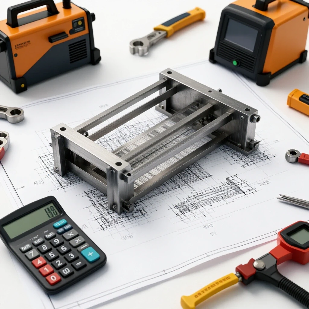
CNC integration allows you to use the original digital design files to verify that the finished welded assembly has not warped or pulled out of alignment during the heating process. This ensures that the final product matches the customer’s specifications exactly.
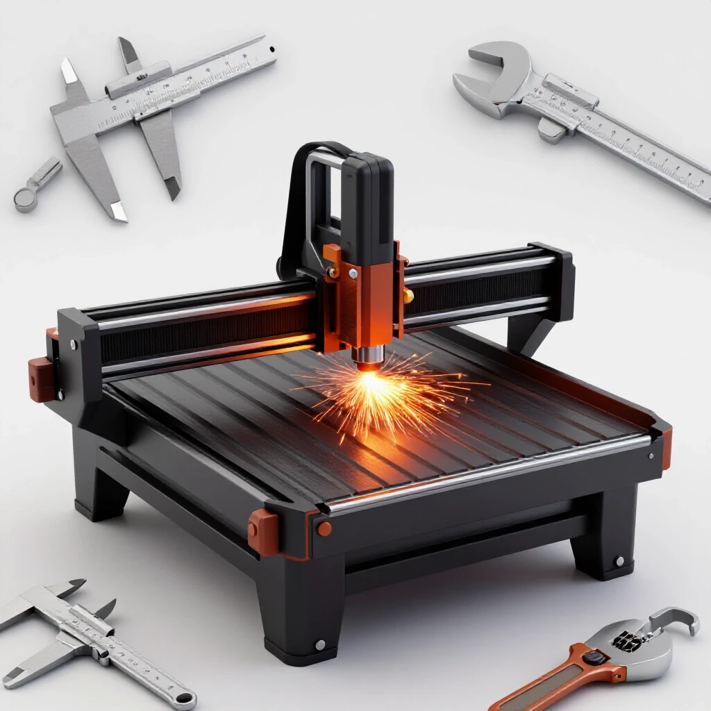
When I integrated a CNC plasma table into my workflow, I realized that the “cut accuracy” was only half the battle. Welding introduces heat, and heat causes “pull.” I now use the CNC table to cut “check templates” or jigs. After welding, I place the part back into the jig. If it doesn’t fit, I know the heat caused the metal to move.
Using stepper or servo motors on your CNC equipment affects how accurately you can cut these verification templates. Servos are “closed-loop,” meaning they know exactly where they are at all times. Steppers are “open-loop” and can lose steps if the gantry hits a piece of slag. For high-precision shops, servos are worth the extra capital cost because they provide a more reliable benchmark for your final part dimensions.
Tracking Quality with a Systematic Framework
To scale effectively, you cannot rely on memory. You need a repeatable framework. I use a simple “Stage-Gate” system. A part cannot move from the welding bench to the paint rack until it passes a specific checklist. This reduces the stress of “hoping” everything is right and replaces it with the confidence of data.
I keep a log of every major assembly. This log tracks the person who performed the final cleaning and the date of the visual check. If we have a failure in the field, I can look back and see if there was a pattern. This is the difference between a “guy in a garage” and a micro-manufacturer.
- Dimensional Check: Does the part match the CAD drawing within +/- 1/16″?
- Surface Prep: Is the metal free of oil, grease, and mill scale?
- Joint Review: Are all welds continuous with no visible cracks?
- Cleanliness: Has all grinding dust been blown out of internal cavities?
Conclusion
Transitioning your shop into a high-efficiency professional space is about mastering the details that happen after the sparks stop flying. By organizing your layout for a linear flow, investing in 3-phase power for better finishing tools, and maintaining a strict visual check for every weld, you protect your reputation and your profit margins.
The goal is to create a system where quality is a predictable outcome, not a lucky accident. Start by looking at your current floor plan. Is there a clear path for a part to be cleaned and inspected? If not, moving a few benches might be the most productive thing you do this week. Once your workflow is set, the transition to automation and higher throughput becomes much less daunting.
Frequently Asked Questions
What is the most common surface defect missed before painting?
Weld spatter is the most frequent offender. It often looks like it is part of the metal, but it is only lightly bonded. If not scraped or ground off, it will eventually detach, leaving an unpainted spot that leads to corrosion.
How much lighting do I really need for a proper inspection?
For detailed work, you should aim for at least 1,000 LUX at the work surface. This is roughly equivalent to a very bright office or a professional drafting table. Standard shop lights usually only provide 300-500 LUX, which is not enough to see fine cracks or porosity.
Why does 3-phase power matter for cleaning welded parts?
Industrial grinders and sanders that run on 3-phase power maintain more consistent torque. When you apply pressure to a single-phase grinder, the RPM often drops, which can cause an uneven surface finish. Consistent RPM leads to a smoother, more paint-ready surface.
Can I use a regular shop vacuum for metal dust collection?
No. Standard shop vacuums do not have the CFM required to capture fine metallic dust at the source. Furthermore, hot sparks from grinding can easily set fire to the paper filters and debris inside a standard vacuum. You need a system designed for metalworking with fire-resistant filters.
What is “undercut” and why is it a problem?
Undercut is a groove or valley melted into the base metal right at the edge of the weld. It acts as a “stress riser.” If you paint over a deep undercut, the paint might hide the fact that the metal is thinner there, which could lead to structural failure under a load.
How do I check for warping after welding?
The best way is to use a “go/no-go” jig or a flat reference surface like a heavy steel table. You can also use your CNC-cut templates to verify that the angles and distances between holes haven’t shifted due to heat expansion and contraction.
Is mill scale okay to leave on if the weld is clean?
Generally, no. Mill scale is a flaky layer of oxide found on hot-rolled steel. While the weld itself might be clean, the paint will only stick to the scale, not the steel. If the scale flakes off later, the paint goes with it. All mill scale should be removed via grinding or sanding.
How do I ensure I haven’t missed any welds in a complex assembly?
I use a “marking” system. As I inspect each weld for slag and spatter, I mark it with a paint pen. If I see a joint without a mark, I know it hasn’t been checked. This is essential for large frames with dozens of small gussets.
What is the best way to clean oil off a part before inspection?
Use a dedicated solvent-based degreaser and a clean rag. Avoid using “shop rags” that might have been used to wipe up oil previously. Even a tiny fingerprint of oil can prevent paint from bonding and can make it difficult to see fine surface defects during your check.
Does CNC plasma cutting affect the pre-paint process?
Yes. Plasma cutting leaves a “nitride” layer on the edge of the cut. This layer is very hard and can prevent paint from sticking. You must grind the edges of plasma-cut parts back to shiny metal to ensure the best possible finish.
(This article was written by one of our staff writers, Edward Sinclair. Visit our Meet the Team page to learn more about the author and their expertise.)