Ergonomic Workshop Upgrades That Reduce Fatigue (DIY Guide)
After twenty years of running a fabrication shop, I have learned that the most expensive tool in the building is not the CNC plasma table or the three-phase press brake. It is the operator. When I first started, I treated my body like a consumable resource, much like a grinding disc or a bag of welding wire. I pushed through the soreness of lifting heavy plate and ignored the stiffness that came from hunching over a low welding table. However, as my shop transitioned from a hobbyist space into a high-output manufacturing environment, I realized that physical exhaustion was the primary bottleneck to my productivity. If I was too tired to think clearly, I made mistakes in my CAD files; if my back hurt, my weld beads suffered.
Scaling a shop requires more than just faster machines. It demands a systematic look at how we interact with our environment. I began applying the same lean manufacturing principles to my workspace that I used for my production runs. This meant redesigning benches, optimizing material paths, and building custom fixtures to ensure that every movement served a purpose. The goal was to create a space where the work flows naturally, and the physical cost of fabrication is minimized through smart engineering rather than expensive store-bought solutions.
Mapping Material Flow to Eliminate Unnecessary Movement
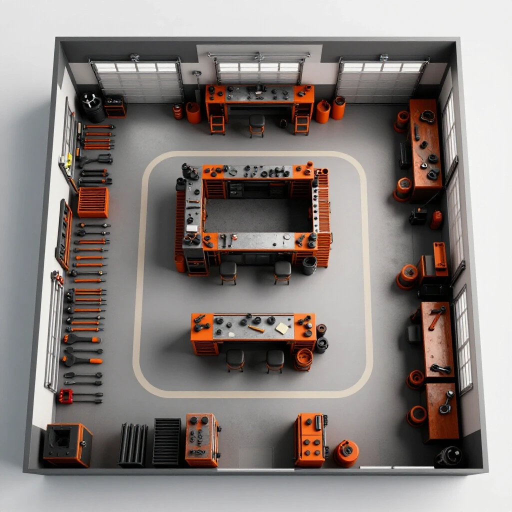
A strategic workshop layout involves analyzing the path a raw piece of steel takes from the delivery truck to the shipping crate. By identifying “material travel loops,” you can pinpoint where you are wasting energy moving heavy stock. A well-designed flow reduces the physical toll of handling materials and keeps the floor clear of trip hazards and clutter.
In my early years, I had my horizontal bandsaw in the back corner and my material rack by the front door. This meant every single cut required carrying heavy stock across thirty feet of floor space. When I finally sat down to map my workflow, I realized I was walking miles every week just to prep material. I shifted to a “linear flow” model. Now, the material rack is adjacent to the saw, which is adjacent to the CNC table. This setup minimizes the “lift and carry” cycles that drain energy before the actual fabrication even begins.
Why Back-and-Forth Foot Traffic Kills Shop Throughput
Linear flow is a layout strategy where materials move in one direction through the shop, from raw stock to finished product. This prevents “bottlenecking,” where work-in-progress piles up and forces the operator to move items multiple times. Reducing these touches preserves physical energy and keeps the production line moving at a steady, predictable pace.
When you analyze your floor plan, look for “spaghetti patterns”—paths where you cross your own tracks multiple times. If you have to move a pallet of parts to get to your welder, your layout is fighting you. I recommend a minimum of a three-foot clear zone around every major machine. This isn’t just for safety; it allows you to use a manual pallet jack or a DIY rolling cart to move heavy assemblies without performing a multi-point turn.
| Layout Type | Material Travel | Space Efficiency | Physical Strain |
|---|---|---|---|
| Random (Evolutionary) | High / Chaotic | Low | High |
| U-Shaped | Moderate | High | Medium |
| Linear (Process-Driven) | Low / Direct | Moderate | Low |
Optimizing Power Delivery for Heavy Fabrication Machinery
A robust electrical system is the backbone of an advanced workshop, especially when integrating industrial-grade equipment. Moving from single-phase residential power to a balanced three-phase environment allows for more efficient motor operation and less heat generation in your tools. Properly planned power distribution reduces the need for long, heavy extension cords that create clutter and physical resistance.
I remember the frustration of tripping breakers every time my air compressor kicked in while I was mid-weld. It wasn’t just an electrical issue; it was a workflow killer that forced me to stop, walk across the shop, and reset the panel. When I upgraded to a rotary phase converter, the difference was immediate. My machines ran cooler and smoother. If you are scaling up, understanding how to balance these loads is critical for maintaining a steady work rhythm.
Building Balanced Three-Phase Systems for High-Output Tools
A three-phase power converter takes standard residential single-phase electricity and generates a third “leg” of power, allowing you to run industrial motors. This is essential for high-capacity mills, lathes, and large compressors. Balancing the voltage across all three legs ensures that your machinery operates at peak efficiency without vibrating excessively or overheating during long production runs.
When installing a rotary phase converter (RPC), you must account for the “starting load” of your largest motor. I typically recommend a converter rated for double the horsepower of your largest machine. For example, if you have a 5HP milling machine, a 10HP RPC provides the necessary overhead. This prevents voltage drops that can crash sensitive CNC controllers. Using a dedicated sub-panel for your three-phase tools also keeps your wiring organized and allows for easier troubleshooting as you add more equipment to your line.
- Rotary Phase Converter (RPC): Best for shops with multiple three-phase machines; provides “true” three-phase power.
- Variable Frequency Drive (VFD): Excellent for single-machine speed control; converts single-phase to three-phase internally.
- Static Phase Converter: Low cost but only provides about 2/3 of the motor’s rated power; not recommended for high-output fabrication.
Designing High-Volume Fume and Dust Extraction Systems
Maintaining clean air is a functional necessity for long-term productivity in a metal shop. Grinding dust and welding fumes don’t just settle on the floor; they settle in your lungs and on your precision machinery. A DIY-built, high-volume filtration system removes these particles at the source, preventing the physical “heavy” feeling that comes from working in a stagnant, smoky environment.
In my shop, I noticed that my afternoon productivity always dipped. It wasn’t just hunger; it was the haze from the morning’s grinding and welding. I designed a multi-stage cyclone dust collection system using heavy-gauge spiral ducting. By calculating the static pressure losses and ensuring I had enough Cubic Feet per Minute (CFM) at each tool, I transformed the environment. The air stayed clear, and I found I could work longer hours without the usual fatigue.
CFM Requirements and Duct Design for Metalworking
CFM, or Cubic Feet per Minute, measures the volume of air an extractor moves. For metal fabrication, you need higher air velocity than woodworking to move heavy metallic dust. Static pressure refers to the resistance the air faces as it moves through ducts and filters. A successful system balances high CFM with low static pressure to ensure pollutants are effectively captured.
To design an effective network, use smooth-walled metal ducting rather than flexible ribbed hoses, which create massive friction losses. For a standard grinding station, you should aim for at least 800 to 1,000 CFM at the hood. I built my own “down-draft” table by fabricating a steel frame with a perforated top, connected directly to the main trunk line. This pulls dust down and away from my face, significantly reducing the amount of grit that ends up on my clothes and in my workspace.
- Calculate Total CFM: Sum the requirements of your two largest tools likely to run simultaneously.
- Size the Main Trunk: Ensure the main duct can handle the total CFM without exceeding 4,000 feet per minute (FPM) velocity.
- Minimize Bends: Every 90-degree elbow adds the equivalent of several feet of straight pipe in resistance.
- Use Blast Gates: Install DIY sliding gates at each tool to focus suction only where it is needed.
Customizing Tooling Stations for Better Body Alignment
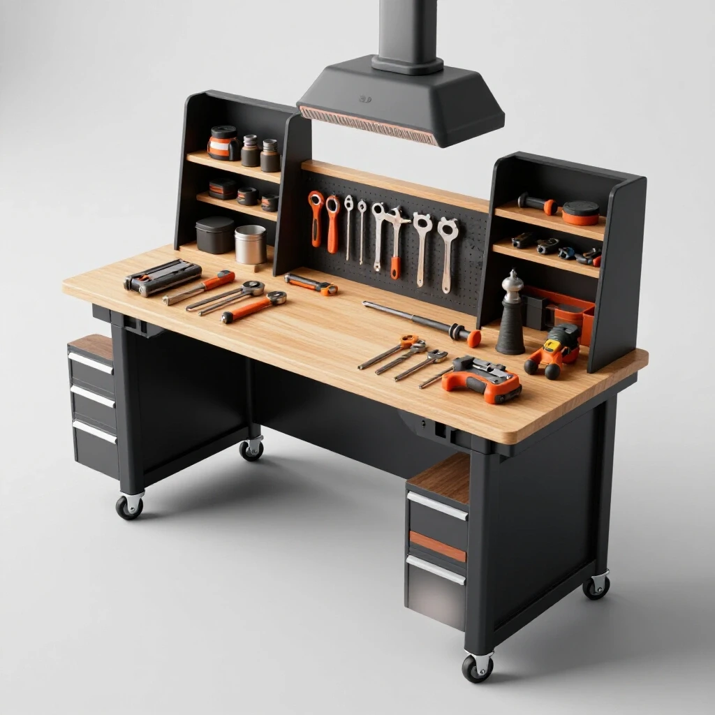
Most standard shop benches are built to a “one-size-fits-all” height that rarely fits anyone perfectly. For an advanced fabricator, spending hours at a bench that is too low leads to a hunched posture and neck strain. By using DIY metal stock to modify bench heights and create adjustable tool stands, you can ensure that your work is always at the optimal level for your specific height and task.
I spent years working on a 34-inch tall bench because that was the “standard.” After a particularly grueling week of TIG welding small parts, I realized I was constantly leaning over to see my arc. I fabricated a set of heavy-duty leveling feet for my main table, raising it to 38 inches. That four-inch difference changed everything. I also built “outrigger” supports for my vise that allow me to swing it out from the bench, giving me 360-degree access to a workpiece without having to twist my body into awkward positions.
DIY Modifications for Benches and Vises
Modifying a workstation involves adjusting the height and reach of your tools to match your natural standing or sitting position. This often requires fabricating custom risers, swing-arms, or pivot points for heavy equipment like vises and grinders. The goal is to keep your elbows at a 90-degree angle and your spine neutral during repetitive tasks like deburring or assembly.
One of my most successful shop upgrades was a “swing-away” grinder station. I used a section of 2-inch square tubing and a heavy-duty trailer hinge to create an arm that holds my bench grinder. When I need to sharpen a tungsten or deburr a part, I pull the grinder to me. When I’m done, I swing it back against the wall. This keeps the tool accessible but out of the way, preventing me from having to reach over other projects or walk to a dedicated grinding area every five minutes.
- Adjustable Height Jigs: Build telescoping legs using two sizes of square tubing and a hitch pin.
- Vise Pedestals: Instead of mounting a vise to a bench corner, weld a heavy pipe pedestal that can be bolted to the floor in a central location.
- Tool Trays: Weld small expanded-metal trays to your welding cart at waist height to keep pliers and brushes within easy reach.
Integrating CNC Plasma and Automated Workflows
The transition to CNC machinery is the single biggest leap an advanced shop can take. It moves the physical burden of cutting and marking from the operator to the machine. However, the integration process has a steep learning curve. A poorly set up CNC plasma table can cause more frustration than it saves if the gantry isn’t level or the software integration is clunky.
When I installed my first 4×8 plasma table, I thought it would solve all my production woes. Instead, I spent the first month fighting “dross” and “torch height” issues because I hadn’t properly leveled the water table. I learned that the foundation of the machine is just as important as the motors. I fabricated a dedicated “computer kiosk” that keeps the sensitive electronics away from the sparks and at an eye-level height, so I wasn’t constantly stooping over a laptop on a bucket.
Leveling CNC Plasma Lines and Configuring Tooling Files
Leveling a CNC system involves ensuring the rails are perfectly parallel and the bed is flat across its entire travel. This prevents the torch from “diving” or “climbing” during a cut, which ruins parts and wastes material. Configuring tooling files means setting up a library of “cut rules” in your CAM software that match your specific plasma cutter’s capabilities, reducing the need for manual trial and error.
I recommend using a precision machinist’s level for the initial setup. Even a 1/16-inch slope over eight feet can cause issues with water levels in the tray. For the software side, I spent a weekend creating a “feed and speed” chart for every thickness of steel I stock. Now, when I start a job, I just load the preset. This reduces the mental fatigue of recalculating settings for every project and ensures consistent part quality every time the torch fires.
| CNC Component | Maintenance Interval | Impact on Workflow |
|---|---|---|
| Gantry Rails | Weekly (Clean/Lube) | Prevents jagged cuts and motor strain. |
| Slats / Bed | Monthly (Clean dross) | Ensures flat material support. |
| Air Filters | Daily (Check moisture) | Prevents torch misfires and tip wear. |
| Software Updates | Quarterly | Improves pathing and nesting efficiency. |
Material Handling and Storage Solutions for High Throughput
As production volume increases, the sheer weight of the material you handle becomes a major factor in shop exhaustion. Moving 10-gauge sheets or 20-foot sticks of tubing by hand is a recipe for a short career. DIY material handling solutions, such as rolling A-frame racks and simple jib cranes, allow you to use mechanical advantage to do the heavy lifting, preserving your strength for the actual fabrication.
I used to store my sheet metal leaning against the wall. Getting the third sheet back meant moving the first two—heavy, dangerous, and exhausting. I fabricated a “vertical toaster rack” using scrap C-channel and 1-inch tubing. Now, every sheet is accessible individually. I also built a simple overhead trolley using an I-beam and a manual chain hoist. It cost me less than five hundred dollars in materials, but it allows me to load the CNC table by myself without breaking a sweat.
Why Mechanical Advantage is Better than Muscle
Mechanical advantage is the use of tools like levers, pulleys, and gears to multiply the force you apply. In a shop setting, this means using a hoist to lift a 200-pound plate instead of calling a neighbor for help. By building these systems into your shop’s infrastructure, you create a semi-professional environment that can handle heavy industrial tasks with minimal physical risk.
A DIY jib crane is a project that pays for itself in the first month. By welding a heavy-wall pipe to a floor-mounted base and adding a rotating arm, you can cover a 10-foot radius of your shop. I use mine to move heavy weldments from the table to the floor. It’s about working smarter, not harder. When you aren’t fighting gravity all day, you have the energy to focus on the precision work that actually makes you money.
- A-Frame Carts: Build these on heavy-duty 6-inch casters to move full bundles of tubing easily.
- Sheet Flippers: Fabricate a simple hinged frame to help transition large sheets from vertical storage to a horizontal cutting bed.
- Scrap Bins: Put every scrap bin on wheels. A full bin of steel is impossible to move otherwise.
Actionable Tracking Frameworks for Shop Efficiency
To truly optimize a shop, you need to measure what is happening. I keep a simple “Efficiency Log” next to my main control panel. I track how long it takes to set up a job, how much time I spend looking for tools, and how I feel at the end of the day. This data-driven approach takes the guesswork out of shop improvements. If I notice I’m spending twenty minutes a day looking for my 1/2-inch wrench, I know it’s time to fabricate a dedicated wrench rack at the machine.
I also use a “Machine Amortization Sheet” to track the cost of my upgrades. By seeing how much time a new DIY jib crane saves me per week, I can calculate exactly when the project has paid for itself in saved labor. This financial clarity reduces the anxiety of scaling. You aren’t just spending money; you are investing in a system that increases your capacity and extends your working life.
Workshop Layout Matrix
| Task Area | Primary Bottleneck | DIY Solution | Efficiency Gain |
|---|---|---|---|
| Cutting | Material handling | Rolling saw infeed/outfeed | 30% faster prep |
| Welding | Part positioning | Adjustable height table | 25% less back strain |
| Grinding | Dust / Cleanliness | Downdraft table / Cyclone | 40% better air quality |
| CNC | Setup time | Dedicated tool library | 50% less CAD/CAM prep |
Conclusion
Transitioning a workshop from a hobbyist setup to a high-output fabrication space is a journey of a thousand small adjustments. It starts with the realization that your physical well-being is a critical component of your shop’s success. By mapping your material flow, balancing your power, and fabricating custom solutions for height and reach, you create an environment that supports your work rather than hindering it.
The most successful upgrades I’ve made over the last two decades weren’t the ones I bought out of a catalog. They were the ones I built myself to solve a specific physical bottleneck. Start small. Pick one area of your shop that causes you the most frustration or fatigue. Apply these lean principles, weld up a solution, and measure the results. Over time, these incremental changes will transform your shop into a highly efficient, professional space where you can produce high-quality work for years to come.
FAQ
What is the best way to determine the ideal bench height? Stand with your shoulders relaxed and your elbows bent at 90 degrees. The distance from the floor to your forearms is generally the best height for precision work like TIG welding. For heavy assembly or manual sawing, drop that height by 3 to 5 inches to allow for more leverage.
How do I calculate the static pressure for my DIY dust collection? Static pressure is calculated by adding the resistance of your longest duct run, every elbow, and the filter itself. Most DIY builders use online calculators where you input duct diameter and length. Aim to keep your total static pressure below 8 to 10 inches of water for a standard 2HP to 3HP collector.
Is a Rotary Phase Converter better than a VFD for a small shop? An RPC is better if you have multiple three-phase machines that you want to run from a single power source. A VFD is better for a single machine where you want precise speed control. If you plan on scaling and adding more industrial tools, the RPC is a more flexible long-term investment.
How much space should I leave around my CNC plasma table? You should have at least 3 feet of clearance on three sides to allow for material loading and maintenance. If you use a forklift or pallet jack, ensure your main aisles are at least 5 to 6 feet wide to allow for safe maneuvering of heavy sheets.
Can I use PVC pipe for my shop’s air filtration ducts? It is generally discouraged in professional shops. PVC can build up a static charge that may lead to sparks, and in a metal shop, the hot sparks from a grinder can melt or ignite the plastic. Smooth-walled galvanized steel ducting is the industry standard for a reason.
What is the most common mistake when scaling a fabrication shop? The most common mistake is buying faster machines without fixing the layout first. A faster laser or plasma cutter won’t help if you are still spending hours moving material by hand or tripping over cords. Fix the flow before you add the speed.
How do I balance the “third leg” on my rotary phase converter? You use a multimeter to measure the voltage between each pair of wires (L1-L2, L2-L3, and L1-L3) while the converter is running. You want the voltages to be within 5% of each other. This is usually adjusted by adding or removing “run capacitors” within the converter’s control box.
What are the signs that my shop layout is inefficient? If you find yourself moving the same piece of material more than three times before it is finished, your layout is inefficient. Other signs include “hidden” tools, cluttered walkways, and physical exhaustion early in the workday.
How do I prevent my CNC gantry from racking? Racking occurs when one side of the gantry moves faster than the other. Ensure your drive belts or rack-and-pinion gears are tensioned identically on both sides. Using a “homing” sequence that squares the gantry against physical stops every time you power up is a reliable DIY fix.
Why is air quality management considered a lean manufacturing principle? Lean is about removing waste. Poor air quality leads to “waste” in the form of operator fatigue, increased cleaning time, and premature equipment failure. By managing air quality, you maintain a higher “uptime” for both your machines and yourself.
(This article was written by one of our staff writers, Edward Sinclair. Visit our Meet the Team page to learn more about the author and their expertise.)