How to Check Symmetrical Parts Before Final Welding (Tips)
I have spent the last 14 years in metal fabrication shops, ranging from small custom garages to industrial structural sites. During that time, I have seen projects that looked perfect on paper fail because a single measurement was off by a fraction of an inch before the final arc was struck. There is a specific kind of anxiety that comes with fabrication. You worry about the structural integrity of your build and whether the finished piece will actually perform under load.
In my early years, I once built a heavy-duty engine stand. I thought I had leveled everything by eye. Once I finished the final passes and hung a V8 block on it, the entire frame leaned three degrees to the left. That lean created a massive shear stress on the mounting bolts that they were never designed to handle. It was a hard lesson in the importance of verifying geometric balance before committing to permanent joints.
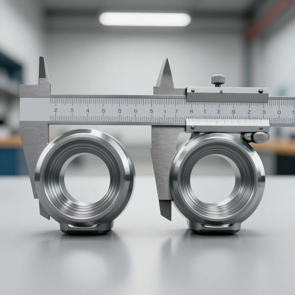
This guide focuses on the rigorous methods I use to ensure that every mirror-image component is perfectly aligned. We will look at manual measurement techniques, the physics of load paths, and the safety protocols required to keep your workshop a productive, injury-free environment.
The Physics of Balanced Geometric Loads
Structural balance ensures that the weight of an object travels through the frame exactly as the designer intended. When a part is not perfectly centered or aligned, it creates an offset load that can lead to premature structural fatigue.
In mechanical engineering, we look at the load path, which is the continuous route that a force takes through a structure. If a frame is lopsided, the force no longer travels vertically through the center of the steel. Instead, it creates a “moment arm,” which is a fancy way of saying it tries to twist the metal. This twisting force, or torque, can exceed the tensile strength of your material. Tensile strength is the maximum amount of pulling stress a material can take before it breaks. For common A36 structural steel, the yield strength—the point where it permanently deforms—is roughly 36,000 PSI.
- A 2:1 safety factor means the structure is twice as strong as its maximum expected load.
- A 4:1 safety factor is standard for overhead lifting or critical structural supports.
- Misalignment by just 1/4 inch can reduce these safety margins by 20% or more.
Building with a focus on geometric consistency is not just about aesthetics. It is about ensuring the Heat Affected Zone (HAZ) of your joints is not subjected to forces it cannot handle. The HAZ is the area of base metal that did not melt but had its microstructure altered by the heat. This area is often more brittle than the rest of the part, making it a prime candidate for a brittle fracture if the load is uneven.
Establishing a Reliable Reference Datum
A datum is a fixed starting point or a “ground truth” from which all other measurements are taken. Without a datum, you are essentially “stacking tolerances,” where a small error in one measurement is added to a small error in the next.
I always start by scribing a permanent centerline on my welding table or the workpiece itself using a carbide scriber. This line acts as my zero point. If I am building a frame with two identical sides, I measure everything from that center line outward. This ensures that even if my overall length is slightly off, the part remains centered.
- Use a fine-point scriber rather than a thick soapstone for your datum lines.
- Verify the flatness of your work surface using a precision straightedge.
- Clamp your primary reference piece to the table to prevent it from shifting during measurement.
If your table is not perfectly flat, your measurements will be skewed. I often use a 48-inch precision straightedge to check for gaps. If I can slide a 0.005-inch feeler gauge under the straightedge at any point, I know I need to shim my workpiece to create a level plane.
Essential Manual Tools for Geometric Verification
To achieve industrial-grade accuracy in a home shop, you need a specific set of manual tools. These tools allow you to check for squareness, parallelism, and equidistant spacing without relying on expensive sensors.
A high-quality combination square is the backbone of my inspection process. I use it to check 90-degree and 45-degree angles. However, you must verify your square is actually square. I do this by drawing a line perpendicular to a straight edge, flipping the square over, and drawing a second line. If the lines are not perfectly parallel, the tool is inaccurate.
- Steel Rules and Tapes: Use a rule with 1/64-inch increments for small parts.
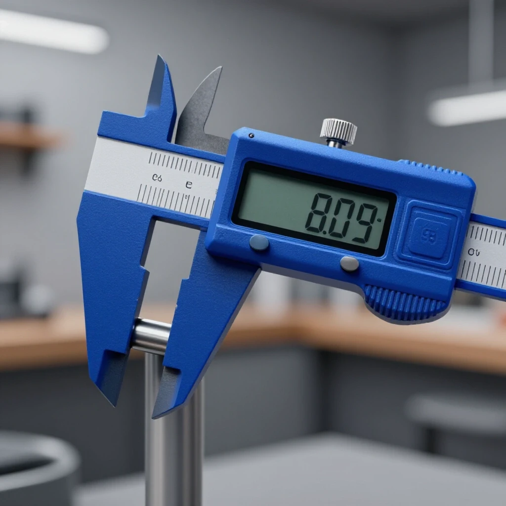
- Calipers: Dial or manual vernier calipers are essential for checking the thickness of matching plates.
- Dial Indicators: These are used to check for “runout” or to ensure a surface is perfectly parallel to the table as you move it.
- Trammel Points: These allow you to measure long distances between two points with much higher accuracy than a sagging tape measure.
| Tool | Primary Use | Accuracy Benchmark |
|---|---|---|
| Combination Square | Angle verification | +/- 0.001 inch per inch |
| Dial Caliper | Internal/External widths | +/- 0.001 inch |
| Trammel Points | Long-distance symmetry | +/- 1/64 inch |
| Feeler Gauges | Gap and flatness checks | 0.001 to 0.030 inch |
Cross-Measurement and Triangulation Strategies
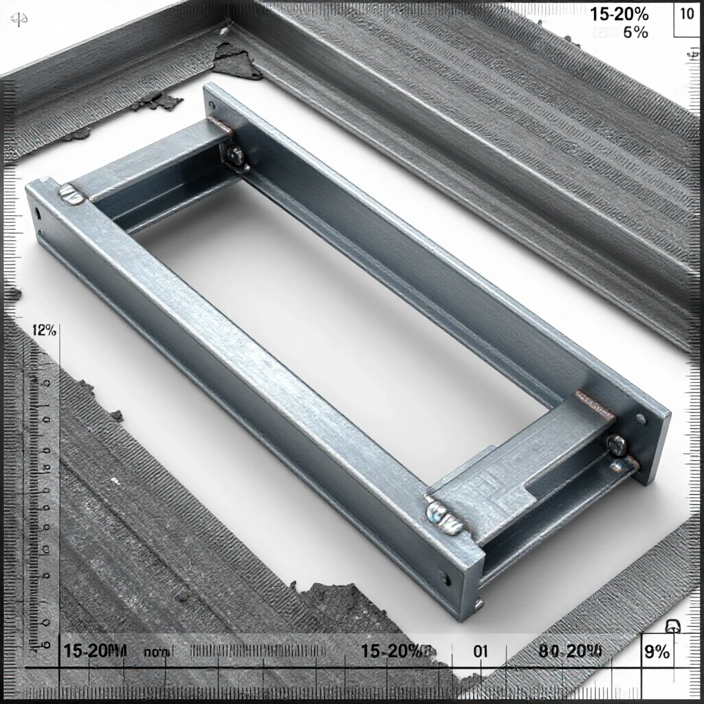
One of the most effective ways to confirm that a rectangular frame is balanced is through cross-measuring. This is based on the geometric principle that the diagonals of a perfect rectangle must be equal.
I pull a tape measure from the top-left corner to the bottom-right corner, then repeat the process for the opposite corners. If the measurements differ by more than 1/16 of an inch on a four-foot frame, the structure is “racked” or skewed. This skewing creates internal stress because the joints are no longer under pure compression or tension; they are being pulled at an angle.
- The 3-4-5 Rule: For large structures, measure 3 feet on one side and 4 feet on the adjacent side. The diagonal must be exactly 5 feet.
- Center-to-Center Checks: When checking the placement of holes or brackets, always measure from the center of the hole, not the edge.
- Parallelism: Use a set of calipers to check the distance between two parallel rails at both ends and the middle.
When I was building a custom utility trailer, I used triangulation to set the axle hangers. If one hanger is 1/8 inch further forward than the other, the trailer will “dog-track,” meaning it pulls to one side. This causes uneven tire wear and puts constant lateral stress on the wheel bearings. By measuring from the center of the hitch to each hanger, I ensured the axle was perfectly perpendicular to the direction of travel.
Managing Thermal Expansion and Tack Stability
Even if your parts are perfectly aligned, the act of welding can pull them out of place. This is due to thermal expansion. As the metal heats up, it expands; as it cools, it contracts and pulls the surrounding metal with it.
I use a sequence of small, strong tack welds to hold everything in place. After the tacks are set, I perform a full secondary inspection. It is a common mistake to assume that because it was straight before the tacks, it is still straight after. I have seen tacks pull a vertical post out of plumb by several degrees in seconds.
- Place tacks on opposite sides of a joint to balance the pulling forces.
- Keep tacks small—roughly 1/4 inch to 3/8 inch in length.
- Never proceed to a final pass if a tack has cracked or if the part has shifted.
If the parts have moved, I carefully cut the tack with a thin cutoff wheel and reset the piece. Trying to “pull” a part back into alignment with heat during the final weld is a recipe for internal stress. This stress stays locked in the metal, waiting for an external load to help it finally snap.
Safety Protocols and Workshop Layout
A cluttered shop is a dangerous shop, and it is also where most measurement errors happen. If you are tripping over cords or struggling to find a clear spot on your bench, you are not going to take the time to verify your work properly.
Workshop safety starts with your personal protective equipment (PPE). When performing these close-up inspections, I always wear Z87+ rated safety glasses. If I am checking parts that have just been tacked, I wait for them to cool or use insulated gloves. A “near-miss” in the shop often happens when a fabricator reaches for a tool and brushes against a hot workpiece.
- Welding Gas Flow: Ensure your shielding gas (typically Argon/CO2 mix) is flowing at 15–20 CFH (cubic feet per hour). Poor gas coverage leads to porosity, which are tiny holes in the weld that destroy structural integrity.
- PPE Ratings: Use a welding helmet with a Shade 10-13 filter depending on your amperage.
- Ventilation: Use a fume extractor or ensure cross-ventilation to prevent the buildup of hexavalent chromium or zinc fumes.
| Hazard | Prevention Strategy | Metric/Standard |
|---|---|---|
| Weld Porosity | Check gas flow and nozzle | 15–20 CFH Flow Rate |
| Eye Damage | Auto-darkening helmet | ANSI Z87.1 / Shade 10+ |
| Structural Failure | Material verification | ASTM A36 (36ksi Yield) |
| Fire Risk | Clear 35ft “Hot Zone” | NFPA 51B Standard |
Structural Joint Verification Benchmarks
Before you lay down the final bead, you must have a checklist. This is the difference between a hobbyist and a professional fabricator. I use a physical checklist for every major project to ensure I haven’t missed a single dimension.
- Datum Alignment: Is the part still aligned with the centerline?
- Angular Accuracy: Have all 90-degree and 45-degree joints been checked with a square?
- Linear Equidistance: Are matching components the exact same distance from the reference point?
- Flatness: Does the structure sit flat on the table without rocking?
- Gap Consistency: Are the gaps between parts uniform to ensure even heat distribution?
If any of these benchmarks are not met, I do not start the final weld. I treat every joint as a potential failure point. If a joint fails, it’s usually because the builder underestimated the forces involved or ignored a small alignment error that grew into a major structural defect.
Real-World Case Study: The Balanced Engine Hoist
A few years ago, I assisted a colleague who was building a heavy-duty shop crane. He had cut all his steel perfectly, but when he went to tack the uprights to the base, he didn’t check the symmetry of the gussets. Gussets are the triangular plates used to reinforce corners.
One gusset was tacked 1/2 inch higher than the other. This seemingly small error meant that when the crane lifted a load, the stress was not shared equally between the two supports. The higher gusset took the brunt of the weight. During a test lift of a 1,000-pound lathe, we heard a sharp “crack.” The weld on the overloaded gusset had developed a longitudinal crack because the geometry was forcing it to carry 80% of the load. We had to stop, support the load with other means, and rebuild the base. If we had checked the equidistant placement of those gussets from the base plates, that failure would have been avoided.
Frequently Asked Questions
What is the most accurate way to check for symmetry on a long frame? The most reliable manual method is cross-measuring the diagonals. Use a high-quality tape measure and ensure the hook is seated the same way on every corner. If the two diagonal measurements are identical, the frame is square and balanced. For lengths over 10 feet, use trammel points to avoid the “tape sag” that can introduce errors.
How much of a measurement difference is acceptable before welding? For most structural garage projects, a tolerance of 1/16 of an inch is the standard. If you are working on precision machinery mounts, you should aim for 1/32 of an inch or less. Anything beyond 1/8 of an inch will likely cause visible alignment issues and uneven load distribution.
Why does my part move even after I have clamped it down? Metal is elastic. Even when clamped, the heat from tack welding causes localized expansion. When the metal cools, it contracts with thousands of pounds of force. This is why a sequence of staggered tacks is better than one long weld. The clamps should remain in place until the tacks have cooled to room temperature.
How do I check if two holes are perfectly aligned across a frame? Pass a tight-fitting “drift pin” or a piece of cold-rolled round bar through both holes. If the bar slides through without binding, the holes are aligned. If you have to hammer the bar through, the holes are offset, which will create shear stress on whatever bolt or pin you eventually install.
What is “racking” and how do I prevent it? Racking occurs when a rectangular frame becomes a parallelogram. One set of corners becomes obtuse (greater than 90 degrees) while the other becomes acute (less than 90 degrees). You prevent this by using corner magnets or squaring clamps and verifying with the 3-4-5 rule before tacking.
Does the thickness of the metal affect how I check for symmetry? Yes. Thicker materials (1/4 inch and up) require larger gaps for weld penetration, which can make measuring more difficult. Always measure from the “root” or the base of the metal rather than the top of a beveled edge to ensure your dimensions are based on the actual structural footprint.
What should I do if my square doesn’t fit in a tight corner? Use a “set block” or a 1-2-3 block. These are precision-ground blocks of steel that are exactly 1, 2, and 3 inches on their respective sides. You can place the block against one surface and use a rule to measure the distance to the other, ensuring it is consistent along the entire length.
Is it safe to weld if I find a 1/8-inch gap on one side of a symmetrical part? A 1/8-inch gap is significant. It requires more filler metal, which means more heat input. This increased heat will cause that side to pull harder during cooling, likely worsening the asymmetry. It is better to trim the part or use shims to close the gap to a uniform width (usually 1/16 inch) before welding.
How do I verify symmetry on curved parts? Use a flexible steel rule to measure the “arc length” from a central datum point. Mark increments along the curve on both sides. If the distance from the center to the end of the curve is identical on both sides, the part is symmetrical. You can also use a contour gauge to compare the shapes.
Why is the Heat Affected Zone (HAZ) a concern for symmetrical parts? If a part is asymmetrical, the load is uneven. This uneven load often concentrates stress right at the edge of the weld, which is the HAZ. Since the HAZ is often the weakest point of the joint due to grain growth during heating, this is where a structural crack is most likely to start. Perfect symmetry ensures the HAZ is stressed evenly within its design limits.
(This article was written by one of our staff writers, James Harlan. Visit our Meet the Team page to learn more about the author and their expertise.)