How to Transfer Metal Shapes Accurately with Templates (Fix)
In my fourteen years navigating the concrete floors of industrial fabrication shops and structural inspection sites, I have learned that a project’s success is rarely decided at the final weld. Instead, it is won or lost in the quiet moments of the layout phase. I remember a specific incident early in my career involving a heavy-duty equipment trailer frame. The fabricator had used a rough cardboard cutout to mark the gussets for the main cross-members. Because the template flexed during the marking process, the gussets were off by nearly 3/16 of an inch.
This seemingly small error created a gap that the welder tried to “bridge” with extra filler metal. The resulting excessive heat input expanded the heat affected zone weakness, leading to a brittle fracture during a load test just six months later. That failure was a turning point for me. It proved that precision in replicating profiles is not just about aesthetics; it is a fundamental requirement for structural metal load capacity and overall workshop safety. When we talk about moving a design from a concept to a physical piece of steel, we are managing the life cycle of the material’s integrity.
The Physics of Precision Layout and Material Integrity
Precision layout involves translating design dimensions onto physical metal with high fidelity. This ensures that load-bearing components align perfectly, preventing uneven stress distribution and premature structural failure in the finished assembly. When components do not fit tightly, the mechanical load paths are interrupted, forcing the weld joints to carry stresses they were never designed to handle.
In mechanical engineering, we look closely at the yield strength of the material—the point at which metal permanently deforms. If you are working with common A36 structural steel, your yield strength is roughly 36,000 PSI. However, if your layout is inaccurate and you force a fit-up, you introduce “built-in” stress before the structure even sees a load. This is why I insist on using rigid patterns. A rigid pattern acts as a physical constant, ensuring that every hole, notch, and radius is placed exactly where the physics of the design requires it to be.
Selecting Rigid Pattern Materials for Consistent Replication
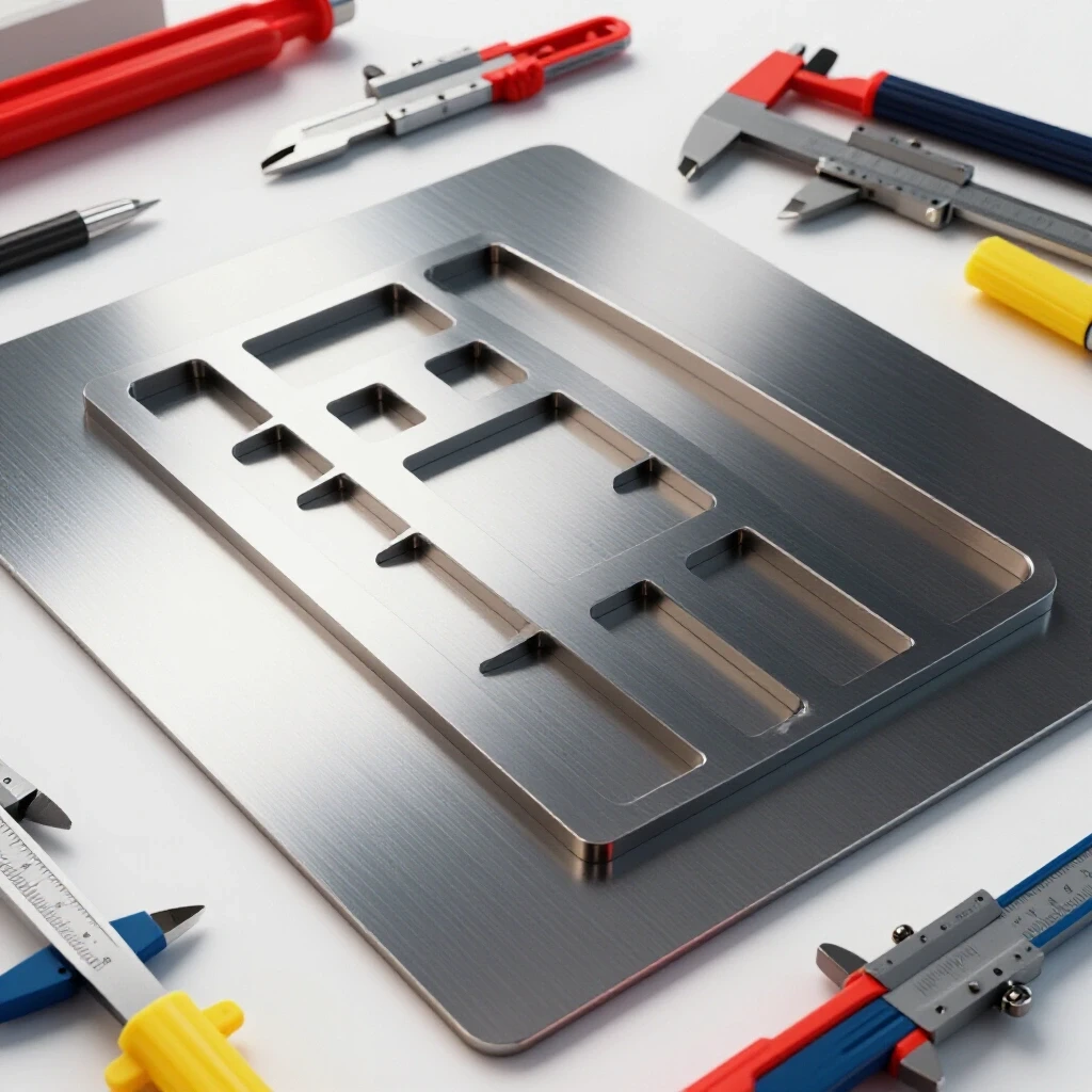
The material used for a pattern must resist deformation, moisture, and compression. Choosing rigid sheet stock like thin steel or high-density plastic ensures that the shape remains constant during multiple transfers and heavy workshop handling. While many hobbyists reach for a cereal box or thin poster board, these materials are prone to “edge crush” and moisture absorption, which can alter dimensions by several millimeters over a long profile.
I prefer using 22-gauge galvanized sheet or 1/8-inch tempered hardboard for my templates. These materials do not compress when a scribe is pushed against them. In a garage fabrication safety context, using a durable template also reduces the time spent near heavy machinery or under suspended loads, as the fit-up is correct the first time. If you must use paper, laminate it to a rigid backing. This prevents the “creep” that occurs when a marking tool drags against a soft edge, a common cause of dimensional drift in complex builds.
Essential Tools for High-Fidelity Shape Duplication
Accurate duplication requires tools that minimize the distance between the pattern edge and the marking line. Scribes, prick punches, and transfer punches are the primary instruments used to create fine, permanent references on the workpiece. A common mistake is using a standard felt-tip marker. A “fine” marker might leave a line 0.5mm wide; on a critical joint, that width represents a margin of error that can lead to poor penetration or excessive gaps.
A tungsten-carbide scribe is my go-to tool. It creates a line only a few thousandths of an inch wide, allowing for extreme precision during the cutting phase. When transferring hole locations, I rely on transfer punches. These are specialized pins that match the diameter of the hole in your template exactly, with a small point in the center to mark the workpiece. This eliminates parallax error—the optical illusion where your viewing angle makes a mark appear shifted from its true center.
Mitigating Heat Affected Zone Weakness through Proper Fit-Up
The Heat Affected Zone (HAZ) is the area of base metal that has had its microstructure altered by welding heat. Tight tolerances achieved through accurate templates reduce the volume of filler metal needed, thereby minimizing HAZ-related brittleness. When you have a gap-free fit-up, you can use less current and move faster, which keeps the total heat input low.
If a profile is transferred poorly, resulting in a 1/8-inch gap on a butt joint that should have been tight, the welder must deposit significantly more metal. This extra heat can cause grain growth in the steel, making the area surrounding the weld far more likely to crack under vibration or impact. By ensuring your shapes are replicated accurately, you are directly protecting the ductility of your base metal and preventing a welding defect troubleshooting nightmare later on.
Comparison of Material Stress and Layout Gaps
The following table illustrates how layout inaccuracies can affect the structural requirements of a standard fillet weld on 1/4-inch plate steel.
| Gap Width (Inches) | Required Weld Size (Leg) | Heat Input Increase | Risk Factor |
|---|---|---|---|
| 0.00 (Tight Fit) | 1/4″ | Baseline | Minimal |
| 1/16″ | 5/16″ | ~25% | Low (Increased Distortion) |
| 1/8″ | 3/8″ | ~50% | Medium (HAZ Embrittlement) |
| 3/16″ | 7/16″ | ~100% | High (Structural Failure Risk) |
Safe Workshop Protocols for Precision Marking and Cutting
Safe workshop protocols involve organizing the workspace to prevent tripping, ensuring proper lighting for layout tasks, and using PPE. These steps protect the fabricator while maintaining the mental focus required for high-accuracy work. I have seen more layout errors caused by poor lighting and fatigue than by lack of skill.
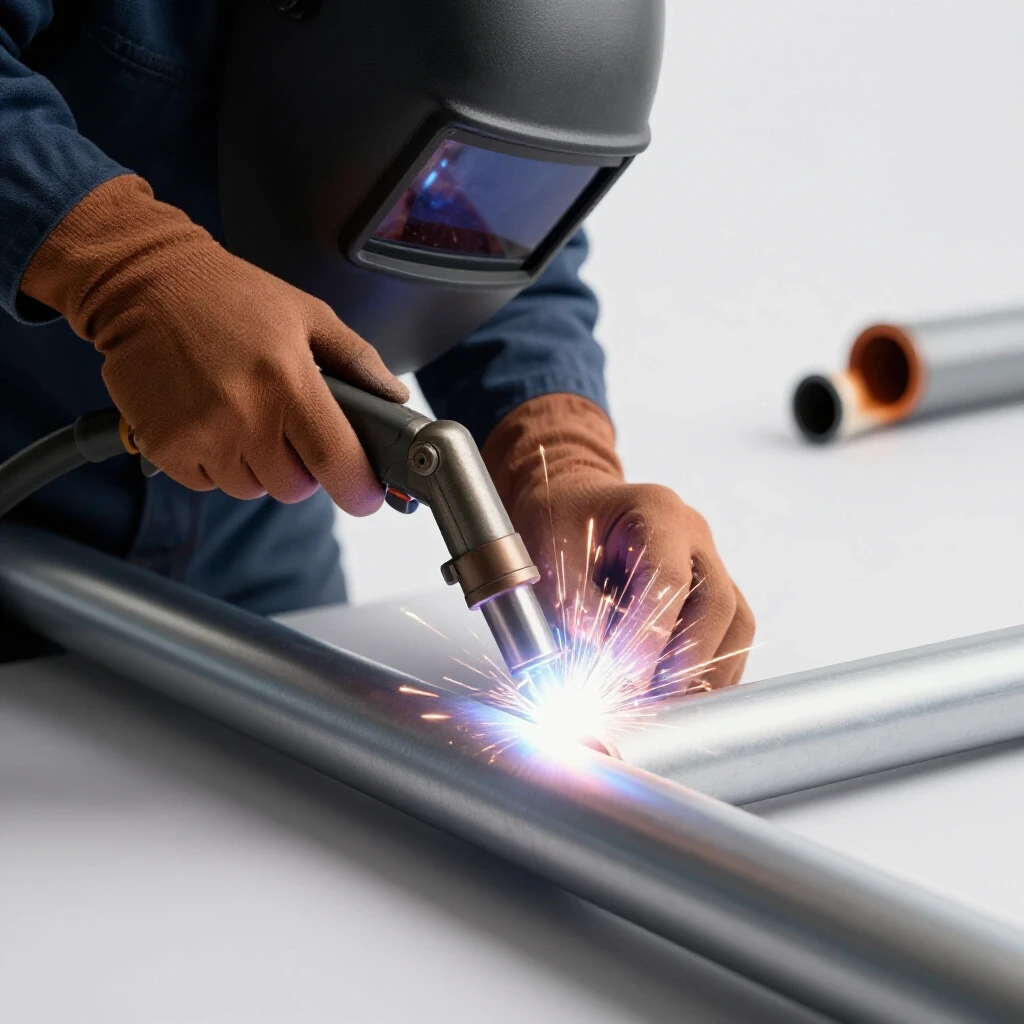
When you are ready to move from the template to the metal, your workshop safety checklist should include verifying your ventilation. If you are marking on galvanized steel or primed plate, the subsequent cutting or tack welding will release fumes. Ensure your welding gas flow rate is calibrated (typically 15–20 CFH for MIG) if you plan to tack-weld your pieces immediately after layout. Proper PPE, including a Shade 10-13 lens for welding and impact-rated clear shields for grinding, is non-negotiable.
Step-by-Step Guide to Transferring Complex Profiles
Transferring complex profiles involves securing a template to a workpiece and using mechanical marking methods to trace the perimeter. This process ensures that irregular curves and hole patterns are replicated without dimensional drift. Follow these steps to maintain a high degree of accuracy:
- Clean the Workpiece: Remove all mill scale, rust, and oil from the metal surface using a wire brush or flap disc. A clean surface allows the scribe to bite and the prick punch to leave a clear mark.
- Secure the Pattern: Use C-clamps or locking pliers to fix the template to the metal. Never rely on hand pressure alone; the template will move as you reach around it.
- Scribe the Perimeter: Hold the scribe at a consistent 90-degree angle to the workpiece. Drag it firmly against the edge of the pattern. One clear pass is better than multiple light passes.
- Mark Center Points: Use a transfer punch for existing holes. If the template has center marks, use a prick punch and a ball-peen hammer to create a small “dimple” that will guide your drill bit later.
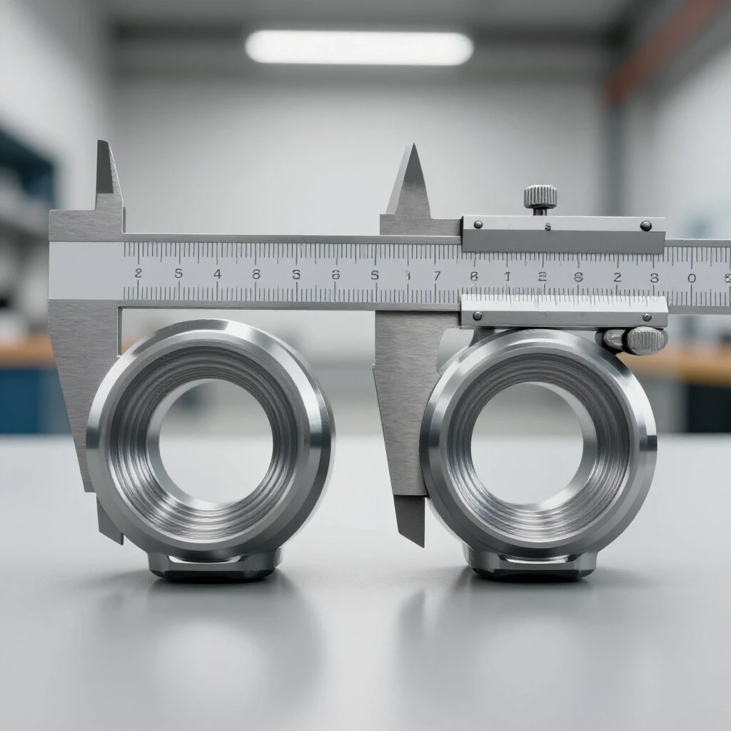
- Verify the Layout: Before removing the clamps, use a machinist’s square or calipers to check at least two “control dimensions” against your original drawing.
Diagnostic Inspection and Structural Load Verification
Post-fabrication inspection uses non-destructive testing (NDT) and physical measurements to confirm the build matches the original pattern. This step identifies internal weld defects and verifies that the structure can handle its intended load capacity. Even if your layout was perfect, the welding process introduces heat that can pull the metal out of alignment.
I recommend using a simple dye penetrant kit for critical joints. This involves spraying a red dye on the weld, wiping it off, and then applying a white developer. If there are any surface-reaching cracks or porosity caused by poor fit-up or gas coverage issues, the red dye will bleed through the developer. This is a low-cost way to ensure your garage fabrication safety standards match industrial requirements. Always check for “undercut” along the edges of your welds, as this is a sign of excessive heat or improper torch angle.
Common Failures in Pattern Replication and How to Avoid Them
Failures often stem from template movement, thick marking lines, or failing to account for the “kerf” or width of the cutting tool. Identifying these errors early prevents wasted material and structural instability. One common mistake is marking the “outside” of the line but cutting on the “inside.”
To avoid this, I always mark my “waste side” with a series of small “X” marks. This tells me exactly which side of the scribed line the saw blade or plasma torch should travel on. Another frequent error is ignoring the thickness of the template itself. If your template is 1/4-inch thick, your scribe might angle under the edge, resulting in a piece that is slightly smaller than intended. Keep your marking tool perfectly vertical to the surface of the workpiece.
Layout Accuracy and Workshop Safety Checklist
Use this checklist before every major cut or weld to ensure structural integrity:
- Is the template material rigid enough to resist bending or edge wear?
- Have all mill scale and oils been removed for clear marking?
- Are clamps positioned so they don’t interfere with the scribe path?
- Has the “waste side” of every cut line been clearly identified?
- Are all hole centers marked with a prick punch to prevent drill bit “walk”?
- Is the lighting adequate to see a fine scribe line clearly?
- Have you accounted for the kerf width of your specific cutting tool?
- Is the welding area clear of flammables and equipped with proper ventilation?
Mastering the Structural Safety Margin
In structural design, we often use a safety factor, such as 2:1 or 4:1. This means the structure is built to handle two to four times the expected maximum load. However, these margins are calculated based on perfect joints. An error in profile replication that leads to a 20% reduction in weld throat thickness effectively cuts your safety margin in half.
When I inspect a project, I look for symmetry. If a bracket on the left side of a frame looks different from the one on the right, it suggests the templates were not used consistently. This asymmetry creates eccentric loading, where the weight is not distributed evenly, leading to twisting (torsion) and eventual fatigue failure. Accurate replication ensures that the load paths remain predictable and the structure behaves as the math intended.
Conclusion
The discipline of accurately duplicating shapes is the foundation of safe metalwork. By moving away from soft, temporary patterns and adopting rigid materials and precision marking tools, you significantly reduce the risk of structural failure. Remember that every gap created by a poor layout is a liability that must be managed with heat and filler metal—both of which can compromise the base material’s strength if not handled perfectly.
Start your next project by treating your layout as a separate, critical phase of construction. Take the time to build a durable template, secure it firmly, and mark with a fine edge. These small, deliberate actions are what separate a “garage build” from a professional-grade structural assembly. Your safety, and the safety of those using your fabrications, depends on the precision you establish before the first spark ever flies.
FAQ: Precision Metal Layout and Safety
How does a wide gap from a poor layout affect weld strength? A wide gap requires more filler metal and higher heat, which expands the heat affected zone. This can lead to a loss of ductility and make the joint prone to brittle cracking under stress.
What is the best material for a reusable metalworking template? For most workshop applications, 22-gauge sheet steel or 1/8-inch tempered hardboard provides the best balance of rigidity and ease of cutting.
Why shouldn’t I use a Sharpie for marking my metal? Felt-tip markers have a wide line width (often 0.5mm to 1mm). This creates a large margin of error compared to a scribe, which produces a line only a few thousandths of an inch thick.
What is parallax error in layout work? Parallax error occurs when you view the template and workpiece from an angle, causing you to mark a point slightly to the side of its true location. Looking directly down at the mark minimizes this.
How do I account for the “kerf” when using a template? The kerf is the width of material removed by the saw or torch. You should always scribe the exact size needed and then guide your cutting tool so the blade stays on the “waste” side of the line.
Can I use a template to mark holes for drilling? Yes, but you must use a transfer punch that matches the hole size in the template. This ensures the center point is exactly where it needs to be, preventing misaligned bolts.
What should my welding gas flow rate be after I finish my layout? For standard MIG welding on mild steel, a flow rate of 15–20 CFH (cubic feet per hour) is generally recommended to ensure proper shielding and prevent porosity.
How do I know if my template moved during scribing? Always check “control dimensions” with calipers before removing your clamps. If the distance between two known points on the metal doesn’t match the template, it shifted.
Does mill scale affect the accuracy of a shape transfer? Yes. Mill scale is an oxide layer that can flake off, taking your marks with it. Always grind or sand the area to shiny metal before laying out your profile.
What is the “waste side” of a cut? The waste side is the portion of the metal that will not be used in the final project. Marking this side ensures you don’t accidentally cut into the dimensions of your finished part.
(This article was written by one of our staff writers, James Harlan. Visit our Meet the Team page to learn more about the author and their expertise.)