How to Document Your Shop Projects for Better Planning (Fix)
I have spent the last 14 years walking the concrete floors of industrial fabrication shops and heavy equipment yards. In that time, I have seen exactly how a lack of clear records leads to structural failure. Early in my career, I watched a custom-built gantry crane frame twist under a load that was well within its theoretical limit. The issue was not the steel itself, but a series of small, unrecorded changes in the weld sequence that caused massive internal stress. That day taught me that memory is a poor tool for structural integrity.
When you work in a home shop, the stakes are just as high. A project that fails can mean wasted material, ruined tools, or a dangerous collapse. I approach every build now with the mindset of a forensic investigator. I document every dimension, every material grade, and every machine setting. This practice turns a chaotic workshop into a controlled environment. By keeping a detailed paper trail, you move away from guesswork and toward a repeatable, safe fabrication process.

Recording Material Specifications and Yield Strength Data
Material documentation involves tracking the specific mechanical properties and origins of every piece of metal used in a build. This process ensures that the steel or aluminum you use actually meets the load requirements of your design. It prevents the common mistake of mixing low-grade alloys into high-stress structural areas.
Understanding the difference between nominal size and actual strength is the first step in a safe build. For example, if you are using A36 structural steel, you need to record its minimum yield strength of 36,000 PSI. If you accidentally swap a piece of A36 for a lower-grade mystery metal from a scrap pile, your structural metal load capacity calculations become useless. I keep a dedicated section in my project log for “Material Origin.”
- Grade and Alloy: Note the specific ASTM or AISI grade (e.g., 1018 Cold Rolled vs. A36 Hot Rolled).
- Heat Numbers: If available, record the heat number from the mill test report to track material consistency.
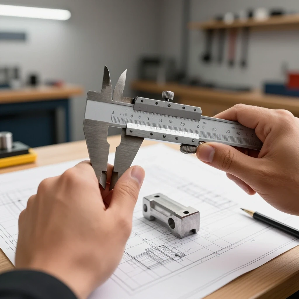
- Dimensions: Measure the actual thickness with calipers. A “quarter-inch” plate might actually be 0.235 inches, which changes your weld penetration needs.
- Surface Condition: Document if the material has mill scale, rust, or oil that requires specific cleaning protocols.
| Material Type | Common Yield Strength (PSI) | Typical Application | Documentation Priority |
|---|---|---|---|
| A36 Carbon Steel | 36,000 | General Framing | Thickness Verification |
| 6061-T6 Aluminum | 35,000 | Lightweight Brackets | Heat Treatment State |
| 4130 Chromoly | 63,000 | High-Stress Tubes | Normalizing Records |
| Grade 8 Bolts | 130,000 | Structural Fastening | Torque Specs |
Why Yield Strength Records Prevent Structural Collapse
Yield strength is the point where metal deforms permanently and will not return to its original shape. By documenting these limits, you can calculate a proper safety margin, typically a 3:1 or 4:1 ratio for overhead or moving parts. If you do not record the specific yield of your material, you are essentially guessing when the structure will fail.
Tracking the Heat Affected Zone (HAZ) Weakness
The Heat Affected Zone is the area of base metal that has not melted but has had its microstructure altered by the heat of welding. Documenting the width of this zone is vital because the HAZ is often the weakest point of a joint. I record the heat input for every critical pass to ensure I am not making the metal brittle or overly soft.
Mapping Structural Load Paths and Design Deviations
Structural load path documentation is the practice of drawing and recording how weight travels through your project to the ground. It involves identifying every joint and fastener that sits in the “line of fire” for mechanical stress. This record allows you to see if a design change in one area will overload another.
When I design a heavy workbench or an engine stand, I start with a simple skeleton sketch. I use arrows to show where the force goes. If I decide to move a cross-member by two inches to make room for a tool, I update that sketch immediately. Small shifts in geometry can turn a simple tension force into a destructive shear force.
Identifying Shear Stress Points in Your Log
Shear stress occurs when forces act in opposite directions across a material, like a pair of scissors cutting paper. In fabrication, this usually happens at bolts or lap joints. I document the number of fasteners and their shear ratings to ensure the load is distributed evenly. Failing to record these details often leads to “zipper failures,” where one bolt snaps and the rest follow instantly.
Calculating and Recording Safety Margins
A safety margin is the extra capacity built into a design to account for unexpected loads or material flaws. I always record the “Design Load” versus the “Ultimate Failure Load” in my project notes. For a shop crane, if the max lift is 1,000 lbs, I document a design that can theoretically handle 4,000 lbs to account for dynamic shifts and weld fatigue.
- Static Load: The weight of the structure itself and any permanent attachments.
- Dynamic Load: The force of moving parts or sudden impacts.
- Safety Factor: The ratio of the material’s strength to the actual expected stress.
Documenting Weld Sequences to Manage Metal Distortion
Weld sequence documentation is a step-by-step plan that dictates the order in which joints are tacked and fully welded. This log is essential for controlling thermal expansion, which causes metal to warp or “pull” out of alignment. By recording the sequence, you can repeat successful layouts or troubleshoot why a frame ended up twisted.
I learned this the hard way while building a 10-foot trailer frame. I welded one side completely before moving to the other. The heat caused the long rails to bow inward by nearly three inches. Now, I use a “staggered” approach and write it down. I weld a few inches on the front left, then move to the back right. This balances the heat input across the entire structure.
Using a Welding Defect Troubleshooting Guide
A defect log helps you identify patterns in your work, such as recurring porosity or undercut. If I notice a specific joint keeps showing signs of internal weld defects, I check my notes on the gas flow and travel speed used for that section. Recording these variables allows you to adjust your technique based on data rather than a “gut feeling.”
Tracking Heat Input and Cooling Rates
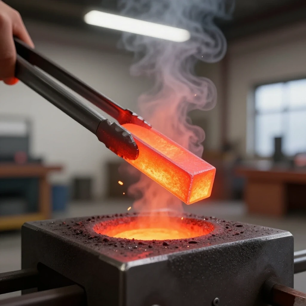
The speed at which a weld cools can change the hardness of the metal. For high-carbon steels, cooling too fast can lead to brittle fractures. I document if I used pre-heat (using a Tempilink stick) or if I allowed the piece to air-cool slowly under a welding blanket. This is especially important for structural metal load capacity in load-bearing frames.
Recording Machine Parameters for Repeatable Joint Integrity
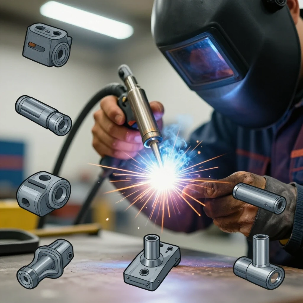
Machine parameter logging involves writing down the exact settings on your welder, saw, or mill for every specific material thickness. This includes voltage, wire feed speed, and shielding gas flow rates. This record eliminates the “test scrap” phase of a project and ensures that your penetration is consistent from the first inch to the last.
I keep a laminated chart next to my MIG welder. Every time I find a “sweet spot” for 3/16-inch plate, I write it down: 19.5 Volts, 320 IPM (inches per minute) wire speed. This ensures that the heat affected zone weakness is minimized and the fusion is deep enough to handle the calculated loads.
- Voltage and Amperage: The primary controls for heat and penetration.
- Wire Feed Speed: Controls the amount of filler metal added to the joint.
- Welding Gas Flow Rate: Usually set between 15–20 CFH (cubic feet per hour) to prevent porosity.
- Electrode Type: Document the specific rod (e.g., E7018) or wire (e.g., ER70S-6) used.
| Material Thickness | Voltage Setting | Wire Speed (IPM) | Gas Flow (CFH) | Joint Type |
|---|---|---|---|---|
| 1/8″ (11ga) | 17.5V | 210 | 18 | Fillet |
| 3/16″ | 19.0V | 280 | 20 | Lap |
| 1/4″ | 21.0V | 350 | 20 | V-Groove |
| 1/2″ | 24.5V | 420 | 25 | Multi-pass |
Why Shielding Gas Porosity Records Matter
Porosity is caused by gas bubbles trapped in the cooling weld metal, often looking like tiny Swiss cheese holes. This is a major structural red flag. If I encounter porosity, I document the weather conditions—like a draft in the garage—and my welding gas flow rate. This helps me realize that a flow rate of 10 CFH is insufficient in a breezy garage fabrication safety environment.
Calibrating Your Workshop Safety Checklist
While I focus on the build, I also document the state of my equipment. I record the last time I checked the seals on my gas regulators and the condition of my ground clamps. A poor ground connection can lead to erratic arcs and cold-lapping, which are hidden defects that can cause a structural joint to fail under load.
Implementing a Project Failure and Adjustment Log
A failure log is a dedicated record of every mistake, near-miss, or “re-work” session during a build. Instead of just fixing a mistake and forgetting it, you document why it happened and how you corrected it. This turns a frustrating error into a valuable data point that prevents future structural design uncertainty.
In my shop, if a hole is drilled 1/16th off or a weld cracks during cooling, it gets a red entry in my notebook. I analyze the cause: was the drill bit dull, or was the clamping pressure too high? This level of detail is what separates a hobbyist from a master fabricator. It builds a personal database of “what not to do.”
- Describe the Error: Be specific. “Weld bead cracked at the crater.”
- Identify the Root Cause: “Fast cooling on 1/2-inch plate without pre-heat.”
- Record the Fix: “Ground out weld, pre-heated to 400 degrees, and re-welded.”
- Preventive Action: “Added a note to pre-heat all plate over 3/8-inch thickness.”
Analyzing Brittle Fracture and Fatigue Points
Brittle fracture happens when a material snaps without bending first, often due to poor material selection or improper welding. By documenting where cracks occur, you can identify fatigue points in your design. If a bracket always cracks at a sharp corner, your log will show you that you need to add a radius to that corner to distribute the stress.
The Value of a Workshop Safety Checklist for Structural Integrity
A structural checklist is a final verification step. Before I call a project “done,” I go through a list: Are all bolts torqued? Are there any visible cold-starts in the welds? Is the frame square within 1/16th of an inch? Documenting this final inspection provides peace of mind that the structure is stable and safe for use.
Organizing Your Physical Project Archive
A physical project archive is a non-digital collection of sketches, material receipts, cut lists, and weld logs kept in a binder or notebook. This system ensures that your technical data is always accessible in the shop, even with dirty hands or no internet. It serves as the “black box” for your fabrication history.
I prefer a heavy-duty three-ring binder with plastic sleeve protectors. I keep my “garage fabrication safety” notes in the front, followed by specific project tabs. This allows me to look back at a project I built three years ago and know exactly what wire speed I used or where I bought the steel. It makes repairs and modifications much safer because the original design intent is preserved.
- Sketches and Blueprints: Hand-drawn or printed diagrams with final dimensions.
- Cut Lists: A record of every piece of metal, its length, and its angle of cut.
- Weld Maps: A diagram showing which joints were welded in what order.
- Testing Results: Notes from any load tests or dye-penetrant inspections.
Why You Should Avoid Relying on Memory
The human brain is excellent at solving problems but terrible at storing precise numbers over long periods. If you build a trailer today and need to add a winch mount two years from now, you won’t remember the wall thickness of the tubing. Having that documented in your archive allows you to calculate the new load capacity without stripping paint to measure the metal.
Standardizing Your Documentation Symbols
To make your logs easier to read, use standard symbols for different types of welds and stresses. Use a triangle for a fillet weld or a circle with a cross for a bolt hole. This creates a professional-grade record that any other fabricator could understand, which is vital if you ever sell the item or need a second opinion on a structural issue.
Frequently Asked Questions
What is the most important thing to document in a new project? The material grade and its yield strength are the most critical. Without knowing the physical limits of your steel, every other calculation for load and safety is just a guess. Always record the source and the specs of your base metal before you strike an arc.
How do I record weld sequences without it taking too much time? Keep a simple top-down sketch of your project. Number the joints in the order you plan to weld them (e.g., 1, 2, 3, 4). As you finish each weld, circle the number. This takes seconds but provides a clear map of the heat distribution across the frame.
What should I do if my documented weld settings aren’t working? Check your environment and machine maintenance. If your log says 19V worked last time but you’re getting spatter now, look for a loose ground, a dirty nozzle, or a change in the ambient temperature. Document these “deviations” to find the new “sweet spot.”
Why does documenting the heat affected zone (HAZ) matter for hobbyists? Even if you aren’t building a bridge, the HAZ is where most failures occur. If you weld too hot or too slow, you can make the surrounding metal brittle. Recording your heat settings helps you stay within the safe “window” for that specific material thickness.
How often should I update my project log? Update it in real-time. Do not wait until the end of the day. Record your settings as soon as the machine is dialed in, and note any design changes the moment you make them. Real-time logging prevents the “I think it was 1/4 inch” errors that lead to failure.
Can I just use a whiteboard for my shop notes? Whiteboards are great for temporary cut lists, but they are easily erased. For structural data and weld sequences, you need a permanent record. Transfer important whiteboard notes to a physical notebook or binder at the end of every work session.
What is a “safety factor” and how do I document it? A safety factor is a multiplier used to ensure a structure can handle more than its intended load. If you expect a shelf to hold 500 lbs, you might design it for 1,500 lbs (a 3:1 safety factor). Document both the “Expected Load” and the “Design Capacity” to track this margin.
How do I document internal weld defects I can’t see? While you can’t see inside a weld without X-ray, you can document the conditions that cause defects. Record if you had a “cold start,” if the gas blew away, or if you saw a “pop” in the puddle. This alerts you to joints that may need extra reinforcement or grinding and re-welding.
What measurements are essential for structural design documentation? Beyond length and width, you must document the “fit-up” or the gap between pieces before welding. A gap that is too wide (e.g., over 1/8th inch on thin material) significantly weakens the joint. Recording these gaps helps you account for shrinkage and final alignment.
Why is gas flow rate part of project documentation? Shielding gas flow (typically 15–20 CFH) is what protects your weld from the atmosphere. If you don’t document it, you might forget that a certain project required a higher flow due to joint geometry or shop drafts, leading to hidden porosity and structural weakness.
How do I track “iterative adjustments”? An iterative adjustment is a change made during the build to fix a problem. If a part doesn’t fit and you have to grind it down, record the new dimension. This ensures that if you ever have to build a second one, your “Master Cut List” is already corrected.
What is the best way to document torque specs for bolts? Create a “Fastener Schedule” in your log. List the bolt size, grade (e.g., Grade 8), and the required torque in foot-pounds. Check them off as you tighten them with a calibrated torque wrench to ensure no structural connections are left loose.
(This article was written by one of our staff writers, James Harlan. Visit our Meet the Team page to learn more about the author and their expertise.)