How to Troubleshoot and Fix Broken Workshop Tools (Guide)
I remember walking into a shop three years ago to look at a used gear-head drill press. The seller had polished the casting and slapped on a fresh coat of “industrial gray” paint, but the second I flicked the switch, the machine screamed. It wasn’t a healthy mechanical hum; it was the sound of a dry bearing fighting for its life inside a poorly shimmed headstock. This is the reality of the workshop world: marketing focuses on horsepower and paint, but longevity lives in the iron and the tolerances.
After 17 years of tearing down machinery and diagnosing mechanical failures, I’ve learned that a tool’s true value isn’t on the spec sheet. It’s found in the ease of alignment, the quality of the spindle bearings, and whether the frame can handle a heavy cut without vibrating like a tuning fork. When you are deciding between a budget import and a premium domestic brand, you aren’t just buying a name. You are buying a specific set of engineering compromises. My goal is to help you see past the branding so you can identify which machines are worth fixing and which ones are destined for the scrap bin.

Evaluating Machinery Materials and Casting Integrity
This phase involves inspecting the base materials of a tool to determine its ability to absorb vibration and maintain its shape under load. High-quality machinery typically uses gray cast iron for its internal dampening properties, while cheaper alternatives often rely on thin, stamped steel frames that flex during heavy operation.
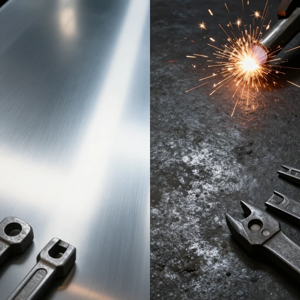
When I evaluate a new piece of equipment, the first thing I do is “ring” the casting. I take a small brass hammer and lightly tap the main frame. A high-quality, dense casting like Class 30 or Class 40 gray iron will produce a dull thud. This indicates the material is excellent at absorbing harmonics. A thin, hollow-sounding ring usually means the manufacturer cut corners on wall thickness. This matters because vibration is the enemy of accuracy. If your machine vibrates, your finishes will be poor, and your cutting tools will dull prematurely.
The weight of the machine is your first clue to its structural health. In the world of metalworking, mass equals stability. A 500-pound lathe will almost always outperform a 200-pound lathe of the same size because the extra iron prevents the bed from twisting. When a machine is out of alignment, the first thing I check is the level of the bedways. If the frame is too light, simply bolting it to an uneven floor can twist the entire structure, throwing your cuts out of true.
- Class 25 Cast Iron: Common in budget hobbyist tools; decent dampening but prone to more internal voids.
- Class 40 Cast Iron: Found in industrial-grade machinery; higher tensile strength and superior wear resistance.
- Ductile Iron: Often used for parts that need to withstand impact, like vise jaws or hammer components.
Assessing Motor Designs and Drive Systems
This process focuses on identifying the type of electrical motor and power transmission system used to drive the tool’s moving parts. Understanding the difference between induction motors, universal motors, and modern brushless drives is essential for predicting the tool’s torque delivery and long-term maintenance needs.
I’ve seen countless motors burn out because they were mismatched for the task. Most budget-friendly portable saws and grinders use universal motors. These are loud, they use carbon brushes that wear out, and they tend to overheat if pushed too hard. For a stationary workshop tool, I always look for an induction motor. These are larger and heavier, but they run much cooler and have no brushes to replace. If a tool won’t start, the first thing I check is the start capacitor—a small cylindrical component that gives the motor the “kick” it needs to get moving.
The drive system is just as important as the motor itself. When I’m comparing machine tool reviews, I look at how the power gets from the motor to the spindle. V-belts are great because they act as a mechanical fuse; if you jam the tool, the belt slips instead of snapping a shaft. However, link-belts are a popular upgrade for older machines because they reduce the vibration caused by a belt that has “taken a set” from sitting in one position too long.
| Motor Type | Common Use | Pros | Cons |
|---|---|---|---|
| Universal | Angle Grinders, Portable Saws | High power-to-weight ratio | Loud, high maintenance, runs hot |
| Induction | Drill Presses, Lathes, Bandsaws | Quiet, long lifespan, constant speed | Heavy, requires large starting current |
| Brushless DC | Modern Cordless & High-end Mills | High efficiency, compact | Complex electronics, higher repair cost |
Checking Frame Rigidity and Torsional Stiffness
Rigidity testing involves measuring how much a tool’s frame deflects or twists when subjected to mechanical force. This is a critical factor in maintaining precision, as any movement in the machine’s structure during a cut will lead to dimensional errors in the finished workpiece.
I once worked on a budget milling machine that couldn’t hold a tolerance better than 0.005 inches. After stripping it down, I realized the column was made of thin-walled tubing rather than a solid casting. To fix this, I had to fill the column with a mixture of epoxy and granite chips to add mass and stiffness. This is a common workaround, but it’s better to buy a rigid frame from the start. Torsional stiffness is the machine’s ability to resist twisting. If you can grab the head of your drill press and visibly move it relative to the table, the frame lacks the stiffness required for metalworking.
To test this, I use a dial indicator mounted on the table, with the tip touching the spindle. I apply a moderate amount of hand pressure to the headstock. If the needle moves more than 0.002 inches, the machine will likely struggle with chatter when using larger drill bits or end mills. Heavy castings dampen these harmonics, ensuring that the energy of the cut goes into removing metal rather than vibrating the machine.
- Box Way Construction: Provides maximum surface area for stability; ideal for heavy milling.
- Dovetail Ways: Common in smaller machines; offers a good balance of precision and adjustability.
- Linear Rails: Found in high-speed equipment; very low friction but less dampening than solid cast ways.
Measuring Spindle Runout and Bearing Quality
Spindle runout refers to the amount of “wobble” or deviation from a perfect circle as a shaft rotates. Measuring this involves using a high-precision dial indicator to ensure the tool’s primary rotating axis is true, which is vital for drilling straight holes and achieving smooth finishes.
If a tool is “broken” in terms of accuracy, the spindle is usually the culprit. Total Indicated Runout (TIR) is the metric we use to measure this. To check a lathe or mill, I place a precision ground rod in the chuck and set my dial indicator against it. As I rotate the spindle by hand, I watch the needle. For most workshop tasks, you want a TIR of less than 0.001 inches. If you see 0.005 inches or more, your holes will be oversized and your finishes will look like a plowed field.
Replacing bearings is one of the most common mechanical repairs I perform. Most mid-range tools use standard deep-groove ball bearings. These are cheap and easy to find, but they don’t handle “axial load” (pushing force) very well. For heavy-duty equipment, I look for tapered roller bearings or angular contact bearings. These are designed to take force from multiple directions, which keeps the spindle stable even during aggressive cuts.
- Clean the Spindle: Ensure the internal taper is free of chips or grease.
- Mount the Indicator: Use a magnetic base to secure the indicator to a non-moving part of the frame.
- Zero the Dial: Place the tip on the rotating surface and set the dial to zero.
- Rotate Slowly: Turn the spindle by hand and record the maximum and minimum readings.
- Calculate TIR: The difference between the high and low points is your runout.
Inspecting Slide Tolerances and Way Alignment
This step involves evaluating the fit and finish of the sliding surfaces, known as “ways,” that allow machine components to move. Proper alignment and the correct amount of “drag” are necessary to prevent the tool from wandering or binding during operation.
When a machine feels “sloppy,” it’s often because the gibs are out of adjustment. Gibs are small strips of metal (usually brass or cast iron) that sit between the sliding surfaces. They are designed to be tightened as the machine wears down. If your lathe carriage or mill table moves or rocks when you push on it, you need to adjust the gib screws. I usually tighten them until the slide binds, then back them off just enough to allow smooth movement.
Alignment is the next hurdle. I’ve seen brand-new saws where the blade wasn’t parallel to the miter slot. This causes “heeling,” where the back of the blade catches the wood or metal, leading to dangerous kickbacks or burnt cuts. I use a dedicated alignment gauge to ensure the blade, fence, and slots are all within 0.002 inches of each other. If they aren’t, I loosen the mounting bolts under the table and shim the trunnions until everything is square.
Testing Speed Controllers and Electrical Health
Electrical troubleshooting focuses on the components that regulate the tool’s speed and power. This includes checking switches, capacitors, and variable speed controllers to ensure the motor receives the correct voltage and responds accurately to user inputs.
Many modern tools use a Variable Frequency Drive (VFD) or a simple potentiometer to control motor speed. If a tool runs at full speed but has no torque, or if it won’t change speeds at all, the controller is likely failing. Before I replace a board, I always check the simple things first. Over 50% of the “broken” tools I’ve repaired just had a blown fuse, a loose wire in the switch box, or a thick layer of conductive metal dust shorting out the terminals.
For tools that use a belt-and-pulley system for speed changes, I check for “pulley wobble.” If the pulley isn’t perfectly centered on the motor shaft, it will create a vibration that mimics a bad bearing. I also look at the “Back-EMF” (Electromotive Force) feedback. High-end controllers use this to sense when the motor is slowing down under load and automatically pump in more voltage to maintain a constant RPM.
- Check the Power Cord: Look for frays or internal breaks near the strain relief.
- Test the Switch: Use a multimeter to ensure continuity when the switch is in the “on” position.
- Inspect the Brushes: If the motor is sparking excessively, the carbon brushes are likely worn out or stuck.
Planning Spare Parts and Maintenance Pipelines
This strategy involves identifying and sourcing critical replacement parts before they are needed. A proactive approach to maintenance ensures that a tool can be repaired quickly, minimizing downtime in the workshop.
One of the biggest mistakes I see buyers make is purchasing a “bargain” machine from a company that doesn’t sell spare parts. A $500 lathe is worthless if you can’t buy a replacement drive gear when one snaps. Before I commit to a major purchase, I check the manufacturer’s website for an exploded parts diagram. If I can’t find a part number for the drive belt or the spindle bearings, I move on to a different brand.
I keep a “maintenance log” for every major tool in my shop. This isn’t anything fancy—just a notebook where I record the date I greased the gears or replaced a belt. I also write down the bearing numbers (like “6203-2RS”) so I don’t have to take the machine apart just to find out what to order. Having a small stock of common consumables, like V-belts and fuses, can turn a week-long shutdown into a ten-minute fix.
- Identify Wear Items: Belts, brushes, bearings, and light bulbs.
- Source Locally: Find a local industrial supply house for bearings and hardware; they are often cheaper than the manufacturer.
- Download Manuals: Keep a digital and physical copy of the parts list for every machine.
- Standardize Hardware: If possible, replace odd-sized bolts with standard Grade 8 hardware to make future repairs easier.
Choosing the Right Tool Class for Your Workload
Selecting the appropriate machinery requires balancing the intended use against the machine’s design limits. Matching the tool’s duty cycle and structural capacity to your specific projects prevents premature mechanical failure and ensures a better return on investment.
When you are choosing workshop machinery, you have to be honest about your needs. If you are only drilling thin aluminum, a lightweight benchtop drill press is fine. But if you plan to push a 1-inch silver and deming bit through 1/2-inch steel plate, that lightweight machine will flex, the belt will slip, and you might even crack the casting. This is where the “duty cycle” comes in. Industrial machines are designed to run 8 hours a day, whereas hobbyist tools are designed for intermittent use.
I always recommend buying the heaviest machine your space and budget allow. You can do small work on a big machine, but doing big work on a small machine is frustrating and often dangerous. Look for “clues” of quality: are the handwheels made of chrome-plated steel or cheap plastic? Are the ways ground smooth or do they still have rough milling marks? These small details tell you how much the manufacturer cared about the final product.
Comparison of Machine Tool Grades
| Feature | Entry-Level / Budget | Mid-Range / Prosumer | Industrial / Professional |
|---|---|---|---|
| Material | Stamped Steel / Thin Cast | Class 25 Gray Iron | Class 40+ Gray Iron |
| Bearings | Unshielded / Generic | Shielded Brand Name | Precision Tapered Roller |
| Motor | Universal (Brushed) | Induction (TEFC) | High-Torque Brushless/VFD |
| Accuracy (TIR) | 0.005″ – 0.010″ | 0.001″ – 0.003″ | < 0.0005″ |
| Repairability | Disposable / No Parts | Good Parts Support | Fully Rebuildable |
Practical Steps for Long-Term Tool Reliability
Maintaining your equipment doesn’t require a degree in mechanical engineering, but it does require consistency. The most common cause of tool failure I see is simple neglect—specifically a lack of lubrication and the accumulation of metal dust. Metal chips are abrasive; if they get into your bearings or onto your sliding ways, they act like sandpaper, grinding away the precision surfaces.
Every month, I do a “walk-around” inspection of my shop. I check for loose bolts, apply a fresh coat of way oil to the bare metal surfaces to prevent rust, and blow out the motor vents with compressed air. If I notice a new noise or a slight increase in vibration, I investigate it immediately. Catching a failing bearing early can save the shaft it’s riding on. If you wait until the machine seizes, the repair bill will triple.
In the end, the best tool is the one that stays accurate and reliable through years of hard use. By focusing on the iron, the bearings, and the electrical components, you can cut through the marketing hype and make an investment that pays off every time you flip the switch.
Frequently Asked Questions
What is the most common cause of a motor hum without rotation? This is usually caused by a faulty start capacitor or a seized bearing. If the motor hums, turn it off immediately to avoid burning the windings. Try rotating the spindle by hand (with power off). If it spins freely, the capacitor is likely the culprit. If it’s hard to turn, the bearings have likely failed or the drive belt is jammed.
How often should I lubricate the ways on my lathe or mill? In a typical hobbyist shop, you should apply a thin coat of “Way Oil” (specifically ISO 68 or similar) every time you use the machine. Unlike standard motor oil, way oil contains “tackifiers” that help it stick to vertical surfaces and prevent “stick-slip” motion, ensuring smooth travel during precise cuts.
Can I replace a universal motor with an induction motor? It is possible, but usually not practical. Induction motors are significantly larger and heavier for the same horsepower rating. You would likely need to fabricate a new motor mount and potentially change the pulley ratios, as induction motors typically run at lower RPMs (1725 or 3450 RPM) compared to universal motors.
Why does my drill press table flex when I apply pressure? This is usually due to a thin-walled column or a lightweight table casting. You can sometimes minimize this by ensuring the table locking handle is extremely tight. For a permanent fix, some fabricators fill the hollow column with a mixture of sand and oil or epoxy to increase rigidity and dampen vibrations.
What is “Spindle Preload” and why does it matter? Spindle preload is the intentional “squeezing” of bearings during installation to remove internal clearance. Proper preload ensures that the spindle doesn’t move axially (up and down) or radially (side to side) under load. If the preload is too loose, you get chatter; if it’s too tight, the bearings will overheat and fail prematurely.
How do I know if my machine’s cast iron is high quality? Look at the unpainted surfaces. High-quality gray iron will have a consistent, fine-grained appearance. If you see large pits, “sand holes,” or jagged edges in the casting, it indicates a poor pour at the foundry. Heavier weight relative to the machine’s size is also a reliable indicator of denser, better-quality iron.
What should I do if my tool’s variable speed controller stops working? First, check for a blown fuse or a tripped circuit breaker on the machine itself. Inspect the potentiometer (the speed knob) for loose wires. If the machine uses a DC motor, check the carbon brushes. If those are fine, the control board may have a failed component, which usually requires a board replacement unless you are skilled in micro-electronics.
Is “Runout” the same thing as “Wobble”? In practical terms, yes. Runout is the technical measurement of how much a rotating part deviates from its intended axis. Even a tiny amount of runout (0.005″) can cause a drill bit to “walk” or a milling cutter to vibrate, leading to poor accuracy and broken tools.
Why are some tools “Ground” and others “Milled” on their surfaces? Grinding is a secondary process that provides a much flatter and smoother surface than milling alone. You want the critical surfaces of your tools—like a table saw top or a lathe bed—to be precision ground. Milled surfaces are cheaper to produce but often have “peaks and valleys” that can affect accuracy.
What is the benefit of a VFD (Variable Frequency Drive) over pulleys? A VFD allows you to change the motor speed electronically by turning a dial, rather than manually moving a belt between pulleys. This saves time and allows for “fine-tuning” the speed to match the specific material and tool size you are using, which extends the life of your cutting tools.
(This article was written by one of our staff writers, Steven Brooks. Visit our Meet the Team page to learn more about the author and their expertise.)