How to Safely Use Angle Grinder Cutoff Wheels (Tutorial)
I have spent 17 years in industrial maintenance and fabrication shops, and if there is one thing I have learned, it is that the most dangerous tool is the one you underestimate. I have torn down hundreds of power tools, from high-end German-engineered units to budget-tier clones, to see how they handle the heat.
Many buyers get caught up in brand wars, but I prefer to look at the motor brushes, the spindle bearings, and the quality of the resin bonds in the discs. A shiny tool body does not prevent a disc from shattering if the spindle has too much play. In this guide, I will break down the mechanics of making clean, safe cuts through metal stock. We will look at the engineering behind the equipment and the physical forces at play when you pull the trigger.
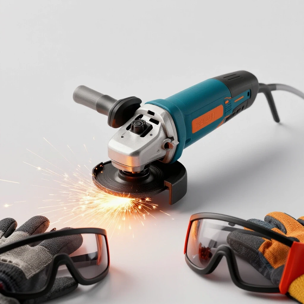
Foundations of Abrasive Cutoff Technology
Abrasive cutoff technology relies on thin, resin-bonded discs designed to wear away material through high-speed friction. These discs are engineered for peripheral cutting only, meaning the edge does the work while the sides remain vulnerable to lateral stress. Understanding the internal structure of these wheels is the first step toward safe operation in any workshop.
Understanding Resin-Bonded Reinforcement
Resin-bonded wheels are composed of abrasive grains, like aluminum oxide or zirconia, held together by a synthetic resin and reinforced with fiberglass mesh. This mesh provides the structural integrity needed to withstand thousands of rotations per minute. Without this internal skeleton, the centrifugal force would cause the disc to fly apart the moment it touches the metal.
When I evaluate these discs, I look at the “use-by” date printed on the center ring. The resin is an organic compound that degrades over time, especially in humid shop environments. A disc that is five years old might look fine, but the bond strength has likely weakened. Interestingly, the fiberglass reinforcement is what gives the disc its “tensile strength,” allowing it to flex slightly without snapping, though this flexibility has very strict limits.
Disc Thickness and Material Compatibility
Choosing the right disc thickness is a balance between cutting speed and structural rigidity. Thinner discs, often around 0.040 to 0.045 inches, cut faster because they remove less material, but they are also more prone to “walking” or bending in the cut. Thicker wheels, near 1/16 of an inch, offer more stability for heavy-walled tubing or thick plate.
- 0.040-inch discs: Best for sheet metal and thin-walled conduit.
- 0.045-inch discs: The “all-purpose” standard for most fabrication.
- 1/16-inch discs: Preferred for structural steel and solid bar stock.
Building on this, you must match the abrasive type to the metal. Using a disc designed for carbon steel on stainless steel can lead to contamination and premature disc failure. Always check the label for the “Fe-S-Cl” free designation if you are working with stainless, as this prevents iron contamination that leads to rust.
Assessing Tool Rigidity and Spindle Accuracy
The mechanical health of your handheld power tool is just as important as the disc itself. If the tool has internal vibrations or a bent output shaft, it will transmit those irregularities to the abrasive wheel. This section covers how to inspect the tool’s core components to ensure they meet the demands of high-speed metal severing.
Measuring Spindle Runout for Stable Cutting
Total Indicated Runout (TIR) is a measurement of how much the spindle deviates from its center of rotation. In my shop, I use a dial indicator to check this. A high-quality tool should have a TIR of less than 0.001 to 0.002 inches. If the runout is higher, the disc will wobble, creating an uneven kerf and increasing the risk of the disc grabbing the material.
Just as you would check a metal lathe comparison guide for spindle accuracy, you must ensure your handheld tool’s output shaft is true. A wobbly spindle causes “chatter,” which is essentially the disc micro-hammering the metal. This vibration fatigues the resin bond and can lead to a catastrophic disc explosion. As a result, I always recommend checking for bearing play by unplugging the tool and trying to wiggle the spindle by hand.
Motor Torque and RPM Synchronization
The motor’s ability to maintain a constant speed under load is critical for a clean cut. When the disc enters the metal, the friction creates drag. If the motor lacks sufficient torque, the RPMs will drop, causing the abrasive grains to “rub” rather than “cut.” This generates excessive heat, which can soften the resin bond.
| Feature | Entry-Level Tool | Professional-Tier Tool |
|---|---|---|
| Bearing Type | Shielded Ball | Sealed Precision Ball |
| Gear Material | Sintered Metal | Machined Heat-Treated Steel |
| Spindle Runout | 0.003″ – 0.005″ | 0.0005″ – 0.0015″ |
| Motor Cooling | Basic Plastic Fan | High-Volume Centrifugal Fan |
When choosing workshop machinery, look for tools with “constant speed circuitry.” This electronic feature senses the load and increases the current to the motor to maintain the set RPM. This prevents the disc from stalling in the middle of a cut, which is a common cause of kickback.
Critical Mounting and Inspection Protocols
Properly mounting the abrasive wheel is a mechanical process that requires attention to detail. A disc that is off-center or improperly clamped will vibrate violently, leading to poor performance and potential danger. These steps ensure the interface between the tool and the disc is secure and balanced.
The Ring Test and Visual Integrity Checks
Before mounting any disc, I perform a visual inspection and a “ring test.” Even a brand-new disc can have hairline cracks from shipping or improper storage. Hold the disc by the center hole and lightly tap it with a non-metallic object, like the handle of a screwdriver. A healthy disc will produce a clear, metallic ring; a cracked disc will give a dull “thud.”
If the disc fails the ring test, I break it in half immediately so no one else accidentally uses it. It is also vital to check the center hub for any signs of rust or deformation. The metal ring in the center of the disc must be seated perfectly flat against the tool’s inner flange. Any grit or debris trapped between the flange and the disc will cause the wheel to run out of true.
Flange Alignment and Tightening Torque
The flanges are the two metal plates that sandwich the disc. The inner flange usually has a “boss” or a raised shoulder that centers the disc. It is imperative that the disc’s bore matches the diameter of this boss perfectly. Most common discs have a 7/8-inch bore, but some smaller tools use different sizes.
- Step 1: Clean the flanges to remove any metal dust or old resin.
- Step 2: Place the disc on the inner flange, ensuring it is centered on the boss.
- Step 3: Thread the outer nut on. For thin cutoff wheels, the “raised” portion of the nut usually faces outward to allow the flat side to grip the disc.
- Step 4: Hand-tighten the nut while holding the spindle lock. Use the provided wrench to snug it down just past finger-tight—do not over-tighten, as the rotation of the tool will naturally tighten the nut during use.
Strategic Workpiece Fixturing and Load Management
How you secure the metal you are cutting is often overlooked, but it is the primary factor in preventing the disc from “pinching.” A pinched disc is the leading cause of kickback and wheel breakage. This section details how to set up your workspace for a controlled and predictable cut.
Preventing Mechanical Pinching
When you cut through a piece of metal, the material’s weight or internal stresses can cause the kerf (the gap made by the disc) to close up. If the kerf closes, it clamps down on the spinning disc like a brake. This creates an immediate transfer of energy that can jerk the tool out of your hands.
To prevent this, always support the material so that the cut opens up as you progress. For example, if you are cutting a long bar, do not support it at both ends and cut in the middle. The bar will sag, and the cut will pinch. Instead, support the bar on one side and let the “waste” piece hang off into the air. This ensures gravity pulls the cut open, keeping the path clear for the disc.
Vibration Dampening and Clamping
Vibration is the enemy of abrasive cutting. If the workpiece is vibrating, it acts like a saw blade against the side of the cutoff wheel. This thins out the disc and can lead to a side-load failure. I use heavy-duty C-clamps or a machinist’s vise to secure the metal as close to the cut line as possible.
Interestingly, the mass of your work surface matters. A heavy steel welding table provides better dampening than a light wooden bench. When I am reviewing milling machine buying tips or lathe bed alignments, I always emphasize cast iron dampening specs. The same logic applies here: the more rigid your setup, the smoother the disc will transition through the metal.
Operational Execution and Kickback Prevention
Once the tool is running, your body position and the way you approach the metal determine your safety. Abrasive cutting is a game of physics. You are managing a high-speed gyroscope, and you must stay out of the “line of fire” while maintaining total control over the tool’s movement.
Body Positioning and the Plane of Rotation
Never stand directly behind the tool. If the disc shatters, the fragments travel in the “plane of rotation”—the same path the sparks take. I always stand to the side of the tool’s path. This ensures that if a failure occurs, the debris flies past me rather than into me.
Keep a firm, two-handed grip on the tool at all times. The side handle is not optional; it provides the leverage needed to resist the gyroscopic forces of the motor. I have seen many people remove the handle to get into tight spaces, but this significantly reduces their ability to react if the disc catches an edge.
Controlling the Spark Path and Depth of Cut
The direction of the sparks tells you which way the tool will move if it kicks back. I prefer to pull the tool toward me so that the sparks fly away. This “climb cutting” approach ensures that if the disc grabs, the tool will jump away from my body. If you push the tool away and it catches, it will kick back directly toward you.
- Initial Contact: Let the tool reach full speed before touching the metal.
- Pressure: Use light, consistent pressure. Let the speed of the disc do the work.
- Depth: Only plunge the disc as deep as necessary to clear the thickness of the metal. Deep plunging increases friction and heat.
- Movement: Move the tool in a straight line. Never twist or tilt the tool while the disc is in the kerf.
PPE and Environmental Safety Standards
The debris created by abrasive cutting is a mixture of tiny metal shards and spent resin. This “dust” is both a respiratory hazard and a fire risk. Proper personal protective equipment (PPE) is the final layer of defense when all other mechanical controls have been met.
Respiratory and Eye Protection
A standard dust mask is rarely enough for metalworking. I use a P100-rated respirator to filter out the fine metallic dust and the fumes from the burning resin. For eye protection, safety glasses alone are insufficient. The high-velocity sparks can easily bounce off your cheek and under the lens. I always wear a full-face shield over my safety glasses for double protection.
Building on this, consider the clothing you wear. Synthetic fabrics like polyester can melt to your skin if hit by a concentrated stream of sparks. Heavy cotton or leather is the standard. I also avoid gloves with loose cuffs, as they can potentially snag on the spinning spindle, though some debate exists about wearing gloves at all with rotating tools. My preference is tight-fitting leather work gloves for heat protection.
Fire Safety and Spark Containment
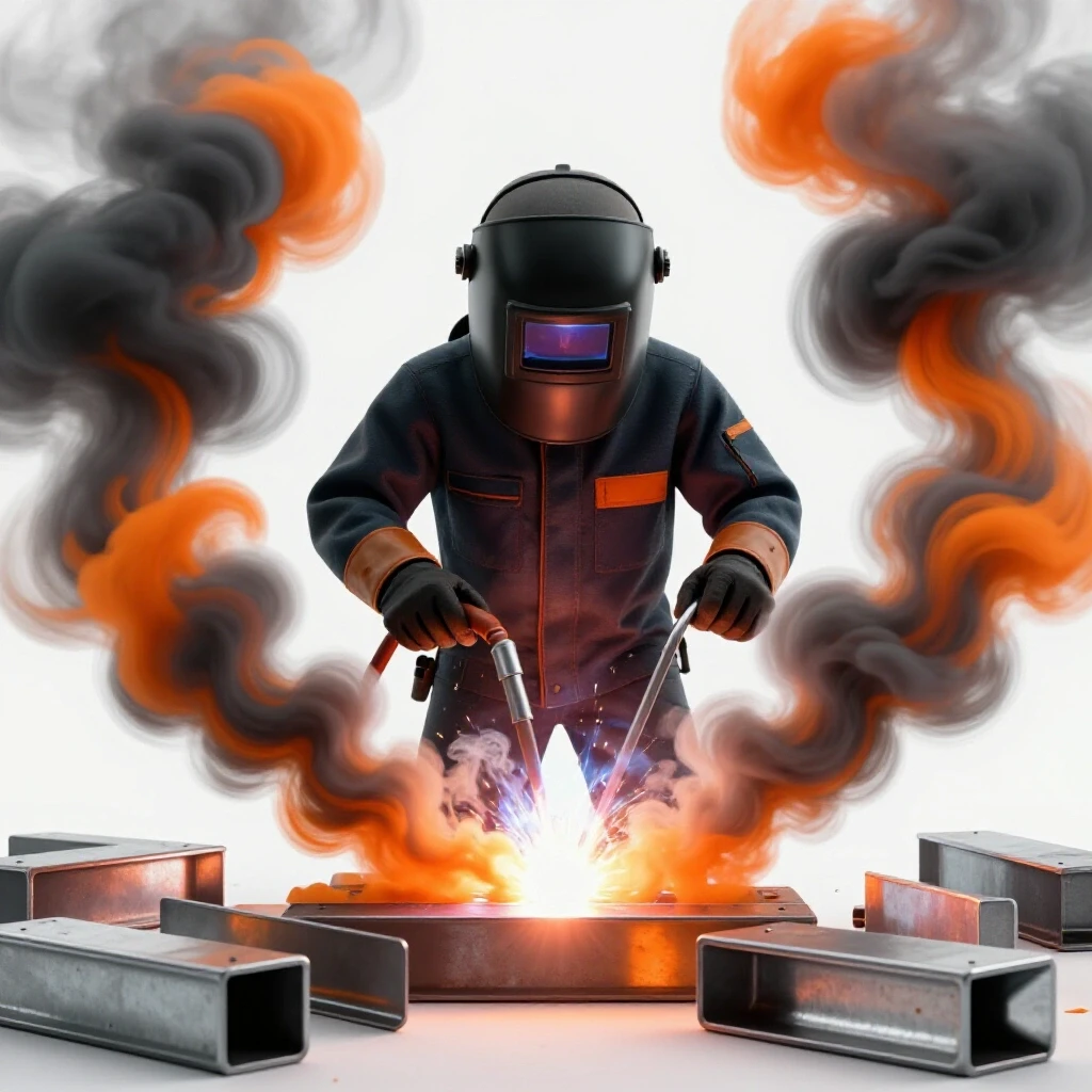
The sparks from a cutoff wheel can travel up to 20 feet and remain hot enough to ignite sawdust, oily rags, or flammable vapors. Before I start cutting, I clear a “spark zone.” If I am working in a confined space, I use fire-resistant welding blankets to catch the debris.
Always keep a fire extinguisher within arm’s reach. It is also a good practice to stay in the shop for at least 30 minutes after you finish cutting. Small “smoldering” fires can start in hidden corners or inside trash cans and may not become visible until long after you have left the room.
Technical Specifications and Tolerances
When you are evaluating which discs to buy, you need to be able to read the technical codes printed on the wheel. These aren’t just marketing numbers; they are engineering limits defined by organizations like the American National Standards Institute (ANSI) or ISO.
Decoding the Abrasive Label
A typical disc might be labeled “A60-T-BF.” Here is what that means in practical terms: * A: The abrasive type (Aluminum Oxide). * 60: The grit size. Lower numbers are coarser; 60 is a standard medium-fine grit for cutoff wheels. * T: The bond hardness. Letters further in the alphabet (like T or U) indicate a harder bond that lasts longer but cuts slower. * BF: Resinoid bond reinforced with fiberglass.
The most critical metric is the Maximum RPM. Never use a disc on a tool that spins faster than the disc’s rating. If your grinder spins at 11,000 RPM, your disc must be rated for at least 11,000 RPM. Using a 7,000 RPM disc on a high-speed tool is a recipe for an immediate structural failure.
Maintenance and Tool Longevity
To keep your equipment in top shape, you must manage the “metal mud”—the mixture of oil and metal dust that gets sucked into the motor. Every few projects, I use compressed air to blow out the motor vents. This prevents the abrasive dust from wearing down the commutator and the brushes.
If you notice the tool getting excessively hot or making a high-pitched whining sound, the grease in the gearbox may have broken down. Most professional-grade tools allow you to open the gear housing and pack it with fresh molybdenum grease. This simple maintenance step can double the life of the tool and ensure the spindle stays stable for accurate cutting.
| Component | Inspection Frequency | Action |
|---|---|---|
| Power Cord | Every Use | Check for nicks or exposed wire |
| Spindle Nut | Every Use | Ensure threads are clean and not stripped |
| Motor Brushes | Every 50 Hours | Replace if worn to less than 1/4 inch |
| Gearbox Grease | Every 100 Hours | Inspect for metal shavings or drying |
Conclusion
Selecting the right equipment and following a disciplined mechanical process is the only way to safely sever metal with a handheld tool. From checking the spindle runout with the same precision you would use for a metal lathe to ensuring your workpiece is fixtured to prevent pinching, every detail matters. By focusing on the engineering of the disc and the tool rather than the brand name, you can achieve clean, industrial-quality results in your own shop. The next time you pick up a cutoff wheel, remember that you are managing a high-energy system; respect the physics, and the tool will work for you.
FAQ
What should I do if the disc starts to vibrate during a cut? Stop immediately. Vibration is a sign that the disc is either cracked, improperly centered, or that the tool’s spindle bearings are failing. Unplug the tool and perform a “ring test” on the disc. If the disc is fine, check the flanges for debris and ensure the workpiece is clamped tightly.
Can I use a cutoff wheel for light grinding or deburring? No. Cutoff wheels are designed for “peripheral” loading only. The fiberglass reinforcement is concentrated to handle the tension of the spinning edge. Side-loading the disc by grinding on the face puts stress on the resin bond that it was never designed to handle, which can lead to the disc shattering.
How do I know when a cutoff wheel is too small to use? As the disc wears down, its diameter decreases, which actually changes the “surface feet per minute” (SFM) at the cutting edge. Once the disc is so small that you have to remove the guard to make a cut, it is past its useful life. Additionally, smaller discs require more RPM to cut effectively, which most fixed-speed tools cannot provide.
Is it safe to use a cutoff wheel without the guard? Never. The guard is your primary shield against flying fragments if a disc fails. Even if it makes the cut more difficult to see, you must adjust your position rather than remove the safety equipment. If the guard is in the way, you likely need a different tool or a better work setup.
Why do some discs seem to “glaze over” and stop cutting? This happens when the metal is too hard for the disc or if you are not using enough pressure. The abrasive grains become dull, and the resin doesn’t wear away to expose new, sharp grains. This is common when using a disc meant for mild steel on hardened tool steel.
Can I use a 4.5-inch disc on a 5-inch grinder? Generally, yes, as long as the RPM rating of the disc exceeds the RPM of the tool and the bore size matches the spindle. However, you should never do the opposite (fitting a larger disc on a smaller tool) as this requires removing the guard and exceeds the tool’s designed gear stress.
What is the “shelf life” of a resin-bonded cutoff wheel? Most manufacturers recommend using discs within three years of the manufacture date. You can usually find the date stamped on the metal center ring. If the disc feels “brittle” or shows any discoloration, it’s best to discard it.
Does it matter which way the label faces when mounting the disc? While many people believe the label must face a certain way, the mechanical priority is the seating of the metal center ring on the flange boss. However, most manufacturers design the disc so that the label faces the nut (outward) to provide a slightly better gripping surface for the flange.
How can I tell if my grinder’s spindle is bent? The easiest way is to mount a new, high-quality disc and spin it by hand. Look at the edge of the disc against a fixed point. If you see the disc “wobble” side-to-side more than 1/32 of an inch, your spindle or flanges are likely out of true.
What is the best way to store cutoff wheels? Store them flat on a level surface in a dry, temperature-controlled environment. Do not hang them on pegs, as this can put constant stress on the center hole. Avoid damp areas, as moisture is the primary cause of resin degradation.
Why are some discs labeled “Inox”? “Inox” is a term for stainless steel. Discs with this label are manufactured without iron, sulfur, or chlorine. This ensures that they won’t leave behind particles that cause stainless steel to rust or corrode at the cut site.
What causes a disc to “explode” suddenly? The most common causes are side-loading (bending the disc), pinching (the kerf closing on the disc), or exceeding the RPM limit. Structural flaws in the disc or a severely wobbly spindle can also trigger a failure, which is why pre-use inspections are so critical.
(This article was written by one of our staff writers, Steven Brooks. Visit our Meet the Team page to learn more about the author and their expertise.)