MIG vs TIG Welding for Custom Steel Roll Cages (Comparison)
I have spent the last 18 years in industrial fabrication shops and millwright environments where a single failed weld or a misaligned frame doesn’t just mean a hobby project is delayed; it means a production line stops or a structural safety component fails. There is a specific kind of frustration that sets in when you are staring at a cluster of porosity in a critical joint or watching a tube frame warp out of square as it cools. You have the tools, and you have the experience, but the material is suddenly behaving like it has a mind of its own.
In my time diagnosing these failures, I have learned that “guessing” is the fastest way to waste expensive mild steel tubing. Whether you are using a wire-fed system or a precision tungsten electrode, the physics of the melt pool do not change. I once spent three days tracking down an intermittent porosity issue on a large tubular assembly, only to find a microscopic crack in the gas hose inside the machine cabinet. That experience solidified my belief in a systematic metalworking diagnostic guide: observe the symptom, isolate the variables, and test one change at a time.
When building load-bearing tubular assemblies, the choice between a semi-automatic wire process and a manual tungsten process dictates your entire troubleshooting workflow. Both have their “gremlins,” and understanding how they interact with thin-wall mild steel is the difference between a structural repair and a structural failure.
Establishing a Metalworking Diagnostic Guide for Tubular Structures
A diagnostic guide is a structured framework used to identify the root cause of a mechanical or metallurgical failure by eliminating variables in a logical order. In the context of mild steel tubing, this means looking at the machine, the material, and the environment before blaming the operator’s technique.
Before you strike an arc, you have to establish a baseline. If your tube frame is pulling 0.125 inches out of alignment, is it the heat input or was the notch fitment loose? I always start with the mechanicals. If the notches in your steel tubing have a gap larger than 0.005 inches, you are already fighting a losing battle with shrinkage. We use the “isolation method” here: fix the fitment first, then look at the heat.
Building a diagnostic path requires you to document what is happening in real-time. If you see the arc wandering, don’t just turn up the voltage. Stop and check your ground clamp. A poor ground creates electrical resistance, measured in Ohms, which can lead to “arc blow” or inconsistent penetration. By following a systematic approach, you turn a chaotic problem into a series of small, solvable tasks.
Why Joint Fit-up is the Foundation of Mechanical Troubleshooting
Mechanical troubleshooting steps begin with the physical interface of the two workpieces, where the quality of the “notch” determines the success of the fusion. In tubular fabrication, the fit-up refers to how tightly the curved end of one tube sits against the surface of another.
I have seen fabricators try to “bridge the gap” with a wire-fed welder on a 1/8-inch gap in 1.5-inch OD tubing. This is a recipe for disaster. When the gap is too wide, the cooling weld metal pulls the tubes inward with immense force. This is basic physics: as the molten steel solidifies, it shrinks. If the fitment is tight (less than 0.010 inches of light showing), there is less room for that shrinkage to distort the frame.
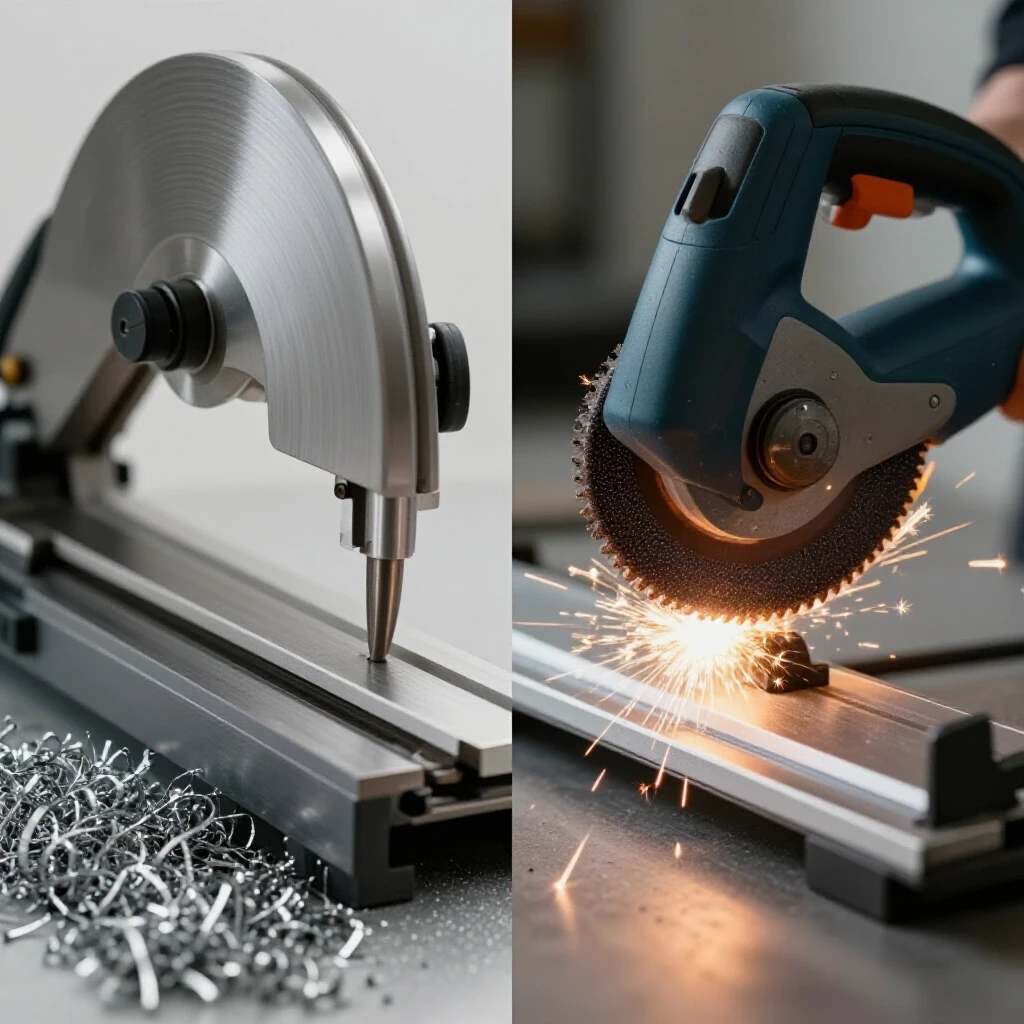
To isolate this variable, use a digital caliper to check your notches. If you are experiencing tool chatter solutions in your tube notcher, it usually stems from spindle backlash or a dull holesaw. A spindle with more than 0.002 inches of play will create a wavy notch, leading to uneven gaps. Tighten your equipment before you blame your welding process for a warped frame.
Troubleshooting Weld Porosity in Wire-Fed and Manual Processes
Weld porosity is the presence of tiny gas pockets trapped in the solidifying metal, often resembling a sponge-like texture that severely compromises structural integrity. It is one of the most common “electrical gremlins” that is actually an atmospheric or contamination issue.
When you find porosity in your mild steel joints, your first step is to check the shielding gas flow. For most tubular work, a flow rate of 15 to 25 cubic feet per hour (CFH) is standard. However, too much flow can cause turbulence, drawing in outside air. I once diagnosed a porosity issue where the fabricator had the flow set to 50 CFH, thinking “more is better.” It was actually creating a vacuum effect that sucked oxygen into the weld pool.
| Symptom | Potential Root Cause | Diagnostic Test |
|---|---|---|
| Pinholes in weld bead | Shielding gas coverage loss | Check for drafts or leaks in gas line using soapy water. |
| Black soot around weld | Surface contamination | Use an acetone wipe on a clean white rag to check for oils. |
| Erratic arc/spatter | Poor electrical ground | Measure resistance between workpiece and ground clamp (should be < 1 Ohm). |
| Internal voids (X-ray) | Moisture in the metal | Pre-heat the tubing to 200°F to drive off surface condensation. |
Building a habit of checking these variables saves hours of grinding. If you are using a wire-fed process, the “liner” inside the torch lead can also collect dust and metal shavings, causing the wire to “stutter.” This feed inconsistency looks like an electrical fault but is actually a mechanical friction issue.
Identifying and Dampening Tool Chatter and Vibrational Issues in Tubing Prep
Tool chatter is a resonant vibration that occurs when the cutting tool and the workpiece are not held rigidly, resulting in a poor surface finish and inaccurate dimensions. In the world of tubular steel, this usually happens during the notching or “fish-mouthing” phase.
If your tube notcher is screaming or vibrating, you are dealing with harmonic resonance. This vibration doesn’t just ruin your holesaw; it creates a jagged edge on the steel that makes a clean fusion weld nearly impossible. To resolve this, I look at the “rigidity triangle”: the machine base, the tube clamp, and the spindle.
- Check the Spindle Backlash: Use a dial indicator to check for side-to-side movement. Anything over 0.003 inches needs adjustment.
- Verify Tube Support: If the tube extends 4 feet past the notch, the unsupported weight creates a “tuning fork” effect. Support the end of the tube with a jack stand.
- Adjust Feed Rate: In manual notching, we often feed too slowly, which causes the teeth to rub rather than cut. This increases heat and vibration.
By isolating these mechanical vibrations, you ensure that the joint you are about to weld is as clean and tight as possible. A smooth notch requires less filler metal and less heat, which directly reduces the risk of warping the entire assembly.
Analyzing Heat-Affected Zones and Metallurgical Defect Troubleshooting
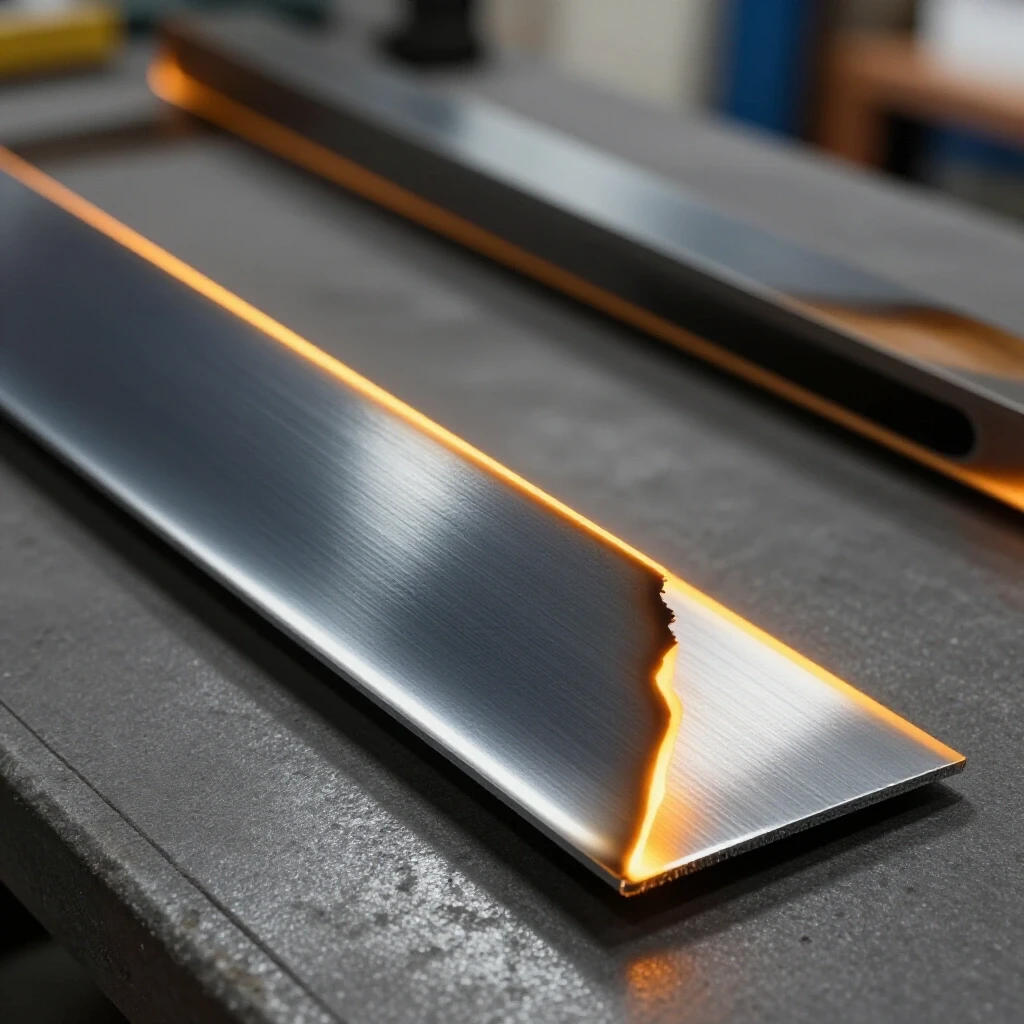
The Heat-Affected Zone (HAZ) is the area of base metal that has not been melted but has had its microstructure and mechanical properties altered by the heat of welding. Understanding the HAZ is critical when comparing high-heat manual processes to faster wire-fed methods.
In thin-wall mild steel tubing, a large HAZ can lead to “brittle zones” right next to the weld bead. If you are using a precision tungsten electrode (TIG), you are often putting more total heat into the part because the process is slower. This results in a wider HAZ. Conversely, a wire-fed (MIG) process is much faster, which keeps the HAZ narrower but can sometimes lead to “cold lap” where the metal doesn’t actually fuse to the tube.
To diagnose HAZ issues, look at the “heat tint” or the colors on the steel. A deep blue or purple color extending more than 1/4 inch from the weld suggests you are moving too slowly or your amperage is too high. If the metal looks “cooked” or gray and flaky, you have likely overheated the carbon in the steel, making the joint prone to cracking under stress.
Mechanical Troubleshooting Steps for Frame Alignment
Frame alignment is the process of ensuring all structural members are in the correct spatial orientation according to the design specifications. When welding complex tubular structures, the heat will always try to pull the structure out of square.
I use a “rule of opposites” when troubleshooting alignment. If I am welding a joint on the right side of a frame, I know it will pull the frame to the right. To counter this, I use a systematic tack-welding sequence. I never fully weld one joint before the rest of the structure is tacked and checked against a lathe alignment checklist or a dedicated jig.
- Level the Base: Ensure your welding table is level within 0.005 inches per foot.
- Square the Main Hoop: Use a digital protractor to verify the vertical angle.
- Cross-Measure Diagonals: On any rectangular section, the diagonals must be within 0.030 inches of each other.
- Tack Weld Sequence: Place 1/4-inch tacks at the 12, 6, 3, and 9 o’clock positions on every tube junction.
- Final Weld-Out: Weld in short 1-inch segments, jumping from one side of the frame to the other to distribute heat evenly.
If you find the frame has moved, do not try to “pull” it back with a ratchet strap while cold. This introduces “locked-in” stress. Instead, use a rosebud torch to gently heat the side opposite the weld to “pull” the metal back into alignment through thermal expansion.
Testing Machine Electronics and Power Delivery
Electrical component testing is the process of using a multimeter or oscilloscope to verify that the welding power source is delivering consistent voltage and amperage. Sometimes, the issue isn’t your technique or the steel; it’s the “back-EMF” or a failing capacitor in the welder.
If you notice the arc “fluttering” or the wire speed changing mid-weld, you need to check your input power. In many shops, we run long extension cords that cause a “voltage drop.” If your 220V machine is only receiving 205V under load, the arc will be unstable.
- Check the Voltage Drop: Measure the outlet voltage while the arc is struck. A drop of more than 5% indicates your circuit is overloaded or the wire gauge is too thin.
- Inspect the Drive Rolls: In wire-fed machines, the tension on the drive rolls should be just enough to feed the wire. Too much tension deforms the wire (making it “birdnest”), while too little causes slipping.
- Test the Potentiometer: Use a multimeter to check the resistance (Ohms) of the wire speed and voltage knobs. The reading should change smoothly as you turn the knob. Any “dead spots” mean the component is failing.
These electrical checks are often overlooked, but they are the root cause of many “unexplained” weld defects. A stable arc is the only way to achieve the deep, consistent penetration required for load-bearing structures.
Comparison of Thermal Input and Penetration Characteristics
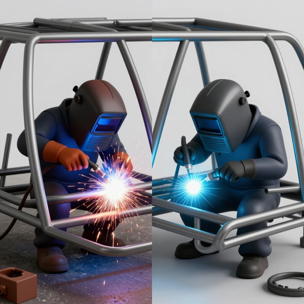
When choosing between a manual electrode and a wire-fed system for mild steel tubing, you are essentially choosing between “control” and “speed.” Both can produce a sound joint, but the failure modes are different.
A wire-fed system (GMAW) uses a continuous spool of wire, which allows for very fast travel speeds. This is excellent for preventing distortion, but it is prone to “lack of fusion” if the voltage is set too low. I always tell my students: “Just because it looks like a weld doesn’t mean it is stuck to the metal.” You must see the “toes” of the weld flowing smoothly into the tube surface.
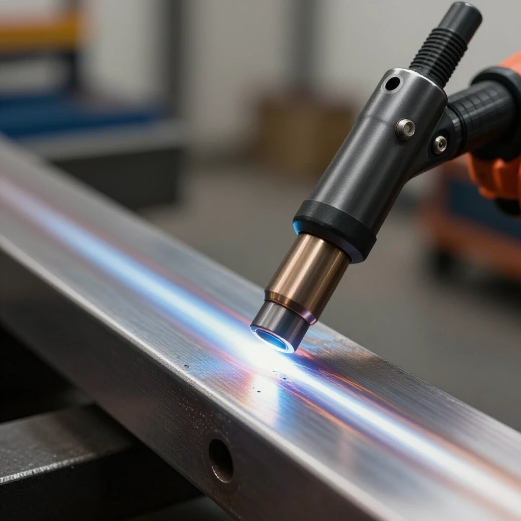
A manual tungsten process (GTAW) allows you to separate the heat source from the filler metal. This gives you ultimate control over the melt pool. However, because it is slower, the total “heat soak” into the tubing is much higher. This increases the risk of the frame warping. If you are working on very thin-wall tubing (0.065 inches or less), the precision of the tungsten electrode is often necessary to avoid “blowing through” the metal.
| Factor | Wire-Fed (GMAW) | Precision Electrode (GTAW) |
|---|---|---|
| Heat Input | Low (Fast Travel) | High (Slow Travel) |
| Risk of Warping | Lower | Higher |
| Common Defect | Lack of Fusion (Cold Lap) | Tungsten Contamination |
| Cleaning Required | Moderate | Extreme (White Metal Clean) |
| Ease of Diagnostics | Moderate (Many variables) | High (Simple variables) |
Final Diagnostic Checklist for Structural Steel Assemblies
Before you call a project “finished,” you must perform a final inspection. I rely on a “post-weld diagnostic” to ensure no hidden issues are lurking in the joints. This isn’t just about looking at the beads; it’s about verifying the structural integrity of the entire system.
- Visual Inspection for Undercut: Look for a “groove” melted into the tube right next to the weld. If it’s deeper than 0.010 inches, it’s a stress riser that could lead to a crack.
- Check for “Cold Start” Craters: Every weld should end with a “fill” to prevent a tiny hole (crater) at the end. These craters are where 90% of structural cracks begin.
- Surface Cleaning: Remove all “silica islands” (glassy brown spots) with a stainless steel wire brush. These can hide small pockets of porosity.
- Dimensional Verification: Re-measure your diagonals. If the frame moved more than 0.060 inches during the final weld-out, you may need to perform a “heat-straightening” procedure.
Mastering these systematic diagnostic methodologies ensures that your fabrication work is not just aesthetically pleasing, but mechanically sound. Whether you are chasing a vibration in your notcher or a pinhole in your weld, the solution is always found in the data, not in the guesswork.
Frequently Asked Questions
Why does my weld have tiny bubbles in it even though I’m using gas? This is typically troubleshooting weld porosity at its most basic level. It is usually caused by a draft in the shop blowing away the shielding gas, a leak in the internal gas hose, or “mill scale” on the steel that wasn’t properly ground off. Check your flow rate (aim for 20 CFH) and ensure the metal is ground to “bright white” steel before welding.
How do I stop my tube frame from warping when I weld it? Warping is caused by uneven heat distribution. To fix this, use a “staggered” welding sequence. Never weld an entire joint at once. Instead, weld 1 inch on the top, move to the opposite side of the frame and weld 1 inch there, and continue rotating. This keeps the total heat soak balanced across the structure.
What is “cold lap” and how do I diagnose it? Cold lap, or lack of fusion, happens when the weld metal sits on top of the base metal without actually melting into it. You can diagnose this by looking at the “toe” of the weld. If the edge of the bead looks like it is “rolling over” rather than blending smoothly into the tube, you need to increase your voltage or slow down your travel speed.
Why is my tube notcher vibrating so much? Tool chatter solutions usually involve increasing rigidity. Check that the tube is clamped as close to the cut as possible. If the spindle has play, you may need to replace the bushings or bearings. Also, ensure you are using a high-quality bi-metal holesaw and a cutting lubricant to reduce friction.
Can I weld mild steel tubing if it has a little bit of rust? Technically yes, but you shouldn’t. Rust is iron oxide, which contains oxygen. When you weld over it, that oxygen is released into the melt pool, causing porosity and “brittle” welds. For structural safety, always grind the weld area until it is shiny and clean.
What is the difference between “backlash” and “play” in fabrication tools? Backlash specifically refers to the clearance or “lost motion” between mating gear teeth or threads (like in a lead screw). Play is a more general term for any looseness in a mechanical system. In a tube notcher, backlash in the feed handle can make it hard to control the cut depth, leading to inconsistent notches.
How do I know if my ground clamp is “good enough”? A good ground is essential for a stable arc. Use a multimeter to check the resistance between the workpiece and the ground clamp. It should be less than 1 Ohm. If the clamp is getting hot during welding, it has high resistance and needs to be cleaned or replaced.
Why does the “Heat-Affected Zone” matter for mild steel? The HAZ is where the metal’s grain structure has changed. If this zone is too large or was cooled too quickly, it can become brittle. In a roll cage or safety structure, a brittle HAZ is where the tube will snap during an impact rather than bending.
How much gap is acceptable in a tube notch? Ideally, you want a “zero-gap” fitment. In practice, a gap of up to 0.010 inches (about the thickness of three sheets of paper) is manageable. Anything larger than 0.030 inches will cause significant shrinkage and frame distortion as you try to fill the void with weld metal.
Is it better to use 0.030″ or 0.035″ wire for 1/8″ wall tubing? For 0.120-inch (1/8″) wall tubing, 0.035″ wire is generally preferred for Gas Metal Arc Welding. It allows for better penetration at lower wire speeds, which gives the operator more control over the heat input. 0.030″ wire is better suited for thinner 0.065″ or 0.095″ wall tubing.
How do I check for “arc blow”? Arc blow occurs when the magnetic field of the welding current deflects the arc away from the joint. If you see the arc “wandering” or pulling to one side, try moving your ground clamp to a different location on the workpiece or wrapping your welding lead around the tube to counteract the magnetic field.
What should I do if I find a crack in a finished weld? Never just weld over a crack. You must “stop-drill” the ends of the crack with a small drill bit, grind out the entire cracked weld bead until you reach solid base metal, and then re-weld the joint. Simply “capping” a crack leaves the structural failure underneath, where it will continue to grow.
(This article was written by one of our staff writers, Paul Whitaker. Visit our Meet the Team page to learn more about the author and their expertise.)