Essential Layout Tools for Precise Metal Projects (Review)
When I started my first garage shop in 2013, I had a limited budget and a lot of ambition. My background as an industrial maintenance technician taught me that a project succeeds or fails long before a single cut is made. In those early days, I tracked every penny and every mistake in a spiral-bound notebook. One of the most painful lessons I recorded was the cost of inaccuracy. If a mark is off by a fraction of an inch, the error compounds as you build. By the time you reach the final assembly, parts do not fit, and material is wasted.
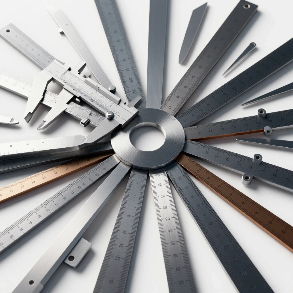
Setting up a fabrication space requires a disciplined approach to choosing marking and measuring instruments. You do not need the most expensive tools, but you do need tools that provide repeatable results. In this guide, I will walk through the core instruments required to achieve dimensional accuracy. We will focus on how these tools function and how to integrate them into a workflow that respects both your time and your budget.
Establishing a Foundation for Dimensional Accuracy
Dimensional accuracy is the degree to which a physical part matches the measurements specified in a plan or drawing. In metalworking, this begins with a clean, organized layout process where every line is placed with intent.
When I was maintaining industrial machinery, we relied on the “datum” principle. A datum is a fixed starting point from which all other measurements are taken. In your home shop, this might be the factory edge of a steel plate or a machined corner of a square tube. Without a consistent starting point, measurements “creep,” leading to parts that are slightly too long or too short.
The first step in any project is identifying these reference points. Once you have a reliable edge, you can use layout tools to transfer your dimensions. This process is more than just drawing lines; it is about creating a physical map on the metal surface that your tools will follow.
The Role of Linear Measurement Devices
Linear measurement devices are tools used to determine the distance between two points along a straight path, such as steel rules or tape measures. These are the most frequently used instruments in any shop.
For metalwork, a standard tape measure is often too bulky and imprecise for fine layout. While a tape is fine for cutting a six-foot length of angle iron, it lacks the resolution needed for hole placement or small brackets. A stainless steel rule is a better choice. These rules usually feature etched graduations, which are more durable and easier to read than printed marks.
I prefer rules that show both 1/32-inch and 1/64-inch increments. In my 2013 shop logs, I noted that switching from a standard ruler to an etched steel rule reduced my layout errors by nearly 40 percent. The thinness of the steel rule allows the markings to sit flush against the workpiece, which eliminates “parallax error”—the slight shift in measurement that happens when you look at a scale from an angle.
Tool Tolerance and Resolution Comparison
| Tool Type | Typical Resolution | Best Use Case |
|---|---|---|
| Steel Tape Measure | 1/16 inch | Rough cutting long stock |
| Etched Steel Rule | 1/64 inch | General layout and part sizing |
| Dial Caliper | 0.001 inch | Critical fitment and hole diameters |
| Vernier Protractor | 1 degree | Angle transfers and bevels |
Precision Scribing and Marking Instruments
A scribe is a tool with a hardened, sharp point used to scratch a permanent, fine line into the surface of a metal workpiece. Unlike a pencil or a felt-tip marker, a scribe does not leave a thick, blurry line that can be easily rubbed off.
In a professional setting, we use scribes because the width of the line matters. A standard carpenter’s pencil leaves a mark that is about 1/16-inch wide. If you cut to the left side of that line versus the right side, your part could be off by a significant margin. A tungsten carbide scribe, however, produces a line only a few thousandths of an inch wide. This level of detail is necessary when you are trying to align parts for a tight fit.
To make these fine lines visible, many fabricators use layout fluid. This is a thin, dyed coating applied to the metal before marking. When you draw the scribe across the dyed surface, it reveals the bright metal underneath. This creates a high-contrast line that is easy to follow even under shop lights.
The Physics of the Scribed Line
When you use a scribe, you are physically displacing a tiny amount of metal. This creates a “V” shaped groove. This groove is not just a visual guide; it can also act as a physical track for other tools. For example, a divider tip or a center punch will naturally want to settle into a scribed line, which helps prevent the tool from wandering.
I have found that maintaining the sharpness of the scribe is vital. A dull scribe requires more pressure, which increases the chance of the tool slipping across the workpiece. In my maintenance days, I kept a small honing stone at my bench specifically for touching up the points of my marking tools.
Dividers and Compasses for Geometry
Dividers are adjustable, two-legged tools with sharp points used for stepping off equal distances or drawing circles and arcs on metal. They work on the same principle as a school compass but are built from hardened steel to withstand contact with metal.
Dividers are particularly useful for finding the center of a circle or laying out a bolt pattern. By setting the legs to a specific distance against a steel rule, you can “walk” the dividers along a line to mark equal segments. This is much faster and more accurate than measuring and marking each point individually with a ruler.
Squaring and Angular Alignment Tools
Squaring tools are instruments used to ensure that two surfaces or lines are exactly 90 degrees to one another. In metal fabrication, “square” is the standard by which almost everything is judged.
The most versatile tool for this is the combination square. It consists of a steel rule (the blade) and a sliding head. The head has a 90-degree face and a 45-degree face. A high-quality combination square allows you to check for squareness, mark 45-degree miters, and measure depths all with one tool.
One mistake I often see beginners make is trusting a square without testing it. Even a new tool can be slightly out of alignment. I use a method called the “four-square check” or the “line reversal test” to verify my squares. You draw a line perpendicular to a straight edge, flip the square over, and see if the blade still aligns with the line. If it doesn’t, the tool is inaccurate and will lead to crooked projects.
Protractors and Bevel Gauges
A protractor is a tool designed to measure or transfer specific angles between 0 and 180 degrees. While many projects rely on 90-degree joints, custom fabrication often requires odd angles for braces or decorative elements.
A simple stainless steel protractor with a pivoting arm is usually sufficient for most home shop tasks. When you need to replicate an angle from an existing object, a sliding bevel gauge is the tool of choice. It doesn’t tell you the degrees of the angle, but it “locks” the angle so you can move it from the workpiece to your marking station.
Angular Accuracy Benchmarks
- 90-Degree Square: Should be accurate to within 0.005 inches over the length of the blade.
- Combination Square Head: Must lock firmly without any wiggle or “play” in the slot.
- Protractor Resolution: Most manual shop protractors offer 1-degree increments, which is standard for fabrication.
Reference Planes and Surface Plates
A surface plate is a flat, heavy slab—usually made of granite or cast iron—that provides a nearly perfect horizontal reference plane. While a full-sized industrial surface plate might be too heavy for a small garage, a small “toolmaker’s” plate is a valuable addition to a layout station.
The surface plate serves as the “zero” for your measurements. When you place a workpiece on the plate, you know the bottom surface is flat. You can then use a height gauge to mark lines at precise elevations from the base. This is the most accurate way to ensure that holes on opposite sides of a part are perfectly aligned.
In my first shop, I couldn’t afford a granite plate immediately. I used a thick piece of float glass as a temporary substitute. It wasn’t as durable as granite, but it provided a much flatter surface than my wooden workbench. This allowed me to keep my layout work consistent while I saved for better equipment.
The Importance of Center Punches
A center punch is a hardened steel rod with a conical point, used to create a small indentation in the metal. This indentation serves as a starting point for a drill bit.
If you try to drill into a flat metal surface without a center punch mark, the drill bit will “walk” or slide across the surface before it starts to bite. This ruins your accuracy. There are two main types: manual punches, which you strike with a hammer, and automatic punches, which use an internal spring mechanism to deliver the strike.
I prefer the manual punch for critical work because it allows for more control. You can place the tip exactly in the intersection of two scribed lines, tilt it to see the placement, and then straighten it before striking. This ensures the hole is exactly where the layout says it should be.
Organizing the Layout Workflow
Accuracy is not just about the tools; it is about the order in which you use them. A structured workflow prevents small errors from growing into large problems. I recommend a “top-down” approach to layout, moving from the largest dimensions to the smallest details.
- Clean the Material: Remove rust, scale, or oil so the marking fluid adheres and the lines are crisp.
- Establish the Datum: Choose one or two edges that will be your primary reference points.
- Apply Layout Fluid: Coat the areas where you expect to make marks.
- Scribe Primary Lines: Use a steel rule or combination square to mark the main boundaries of the part.
- Mark Intersections: Use dividers or a height gauge to locate hole centers or secondary features.
- Punch the Centers: Use a center punch to lock in the locations for drilling or further machining.
Layout Tool Maintenance and Longevity
| Tool | Maintenance Action | Frequency |
|---|---|---|
| Steel Rules | Wipe with light oil to prevent rust | After every use |
| Scribes | Hone the tip on a fine stone | When the line becomes thick |
| Combination Squares | Clean the groove in the blade | Monthly |
| Dividers | Tighten the tension nut | As needed |
Avoiding Common Layout Mistakes
One of the most frequent errors I see in beginner shops is “cumulative error.” This happens when you measure from one mark to the next, rather than measuring every point from the original datum edge. If your first mark is 1/64-inch off, and you measure the next mark from there, the second mark might be 1/32-inch off. By the fifth mark, you are significantly out of spec. Always pull your measurements from the same starting point.
Another pitfall is using the wrong tool for the scale of the work. Using a 25-foot tape measure to mark a 2-inch bracket is a recipe for frustration. The hook on a tape measure is designed to move to account for its own thickness, but this movement can become inconsistent over time. For anything under 12 inches, a rigid steel rule is almost always the superior choice.
Finally, remember that heat affects metal. If you are marking a piece of steel that has just been cut with a saw or a torch, it will expand. If you layout your holes while the metal is hot, the dimensions will change as the part cools. Always wait for the material to reach room temperature before performing precision layout.
Building a Capable Layout Kit
You do not need an exhaustive collection of tools to start. A focused kit of high-quality basics will serve you better than a drawer full of cheap, inaccurate instruments. In my experience, the following items form the core of a reliable layout station:
- 12-inch Combination Square: The workhorse of the shop.
- 6-inch and 12-inch Steel Rules: For various scales of work.
- Tungsten Carbide Scribe: For permanent, fine lines.
- Spring Dividers: For circles and stepping off distances.
- Prick Punch and Center Punch: For marking hole locations.
- Layout Fluid: To make your work visible.
By investing in these tools and learning to use them methodically, you create a foundation for success. Metalworking is a rewarding craft, but it demands respect for the numbers. When your layout is precise, the rest of the fabrication process—the cutting, the fitting, and the assembly—becomes much more predictable and enjoyable.
Frequently Asked Questions
Why is a scribe better than a permanent marker for metal layout?
A permanent marker leaves a line that is typically 0.03 to 0.05 inches wide. In precision work, that width represents a significant margin of error. A scribe scratches a line into the metal that is only 0.003 to 0.005 inches wide. This allows for much higher accuracy when aligning tools or checking fitment. Additionally, scribed lines cannot be accidentally wiped away by oils or coolants during the fabrication process.
How do I check if my combination square is actually square?
The simplest way is the “line reversal test.” Take a piece of material with a perfectly straight factory edge. Hold the square head against the edge and draw a fine line along the blade. Flip the square over so the head is on the same edge but facing the opposite direction. Slide the blade up to your line. If the blade and the line are perfectly parallel, the square is accurate. If they diverge, the square is out of alignment.
What is the difference between a prick punch and a center punch?
A prick punch has a sharper point, usually ground to a 30-degree or 60-degree angle. It is used for the initial, precise placement of a mark at the intersection of scribed lines. A center punch has a wider point, usually 90 degrees, and is used to enlarge the prick punch mark so it can properly guide a drill bit. Using a prick punch first increases the accuracy of the final hole location.
Does the thickness of a steel rule matter?
Yes. Thinner rules are generally preferred for layout because they minimize parallax error. When a rule is thin, the graduated markings sit closer to the surface of the workpiece. This makes it easier to transfer the measurement accurately with a scribe. Thicker rules are more durable but can be harder to use for high-precision marking.
Can I use wood-working squares for metal fabrication?
While you can, it is often not ideal. Woodworking squares are designed for the tolerances of timber, which expands and contracts significantly. Metalworking requires tighter tolerances. Furthermore, metal chips and sparks can damage the softer materials (like brass or wood) often found in woodworking squares. A hardened steel machinist or combination square is better suited for the heat and abrasion of a metal shop.
How do I prevent my layout tools from rusting in a garage?
Most precision layout tools are made of high-carbon steel or stainless steel. To prevent rust, especially in humid garage environments, you should wipe them down with a light coat of machine oil or a dedicated corrosion inhibitor after every use. Avoid storing them in damp areas, and consider keeping them in a lined drawer or a tool roll to protect the precision edges from moisture and physical damage.
What is layout fluid, and is it necessary?
Layout fluid is a thin, fast-drying dye (usually blue or red) that you brush or spray onto the metal. It creates a high-contrast background that makes scribed lines stand out clearly. While not strictly “necessary” for rough work, it is essential for precision layout. It allows you to see exactly where your scribe has traveled and helps you follow lines more accurately during cutting or filing.
Why do some steel rules have “etched” markings?
Etched markings are physically chemically eaten into the surface of the metal, rather than just printed on top. This makes the markings permanent; they will not wear off with heavy use or exposure to solvents. Etched rules are also easier to feel with a scribe or a fingernail, which can help in setting dividers or other tools to a specific measurement.
How often should I calibrate or check my measuring tools?
In a home shop, you should check your primary squares and rules every few months, or any time a tool is dropped. Dropping a combination square can easily knock the head out of alignment. Regular checks ensure that you aren’t building projects based on faulty data, which saves money on wasted material in the long run.
What is a “datum” and why should I care?
A datum is a fixed reference point, line, or surface from which all other measurements are taken. In layout, using a single datum (like the left edge of a plate) prevents “tolerance stack-up.” If you measure every feature from the same edge, your errors won’t accumulate. If you measure from one hole to the next, any tiny mistake in the first hole will be carried over and added to the second, leading to significant inaccuracies.
(This article was written by one of our staff writers, Michael Thompson. Visit our Meet the Team page to learn more about the author and their expertise.)