How to Find Blockages in Shop Dust Collection Hoses (Fix)
When you spend your days chasing 0.002-inch tolerances on a lathe or trying to eliminate the last bit of porosity in a critical TIG weld, you develop a sixth sense for when a system is “off.” It usually starts with a sound—a slight change in pitch from a spindle or a subtle hiss from a gas line. In my eighteen years troubleshooting industrial fabrication setups, I have learned that the most frustrating issues are the ones you cannot see. One of the most common, yet overlooked, performance killers in a busy shop is the gradual loss of suction in your extraction lines.
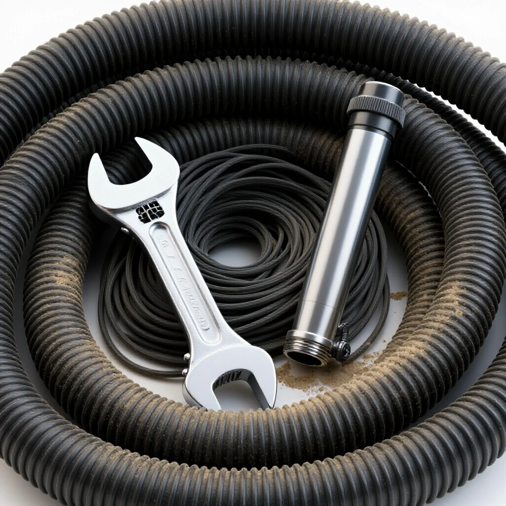
It is a familiar scenario. You are running a high-speed milling operation or a heavy grinding session, and suddenly, the floor is covered in more debris than usual. You check the main unit, and it seems to be running fine. But at the tool interface, the pull is weak. This is where the systematic diagnostic process begins. We do not guess. We do not just start ripping hoses off the wall. We use a methodical approach to isolate the restriction and restore the laminar flow required to keep the workspace clean and the machinery functioning correctly.
Establishing a Systematic Diagnostic Framework
A structured diagnostic framework involves breaking a complex system into smaller, testable segments to isolate the root cause of a performance drop. By eliminating variables one by one, you avoid the trap of “random troubleshooting” and move toward a definitive solution.
In any fluid or air transport system, performance is a balance of volume and pressure. When we talk about suction, we are really talking about Cubic Feet per Minute (CFM) and Static Pressure (SP). If a hose is restricted, the static pressure increases while the CFM drops. I approach this just like I would a hydraulic fault or a shielding gas issue. I start at the source and work toward the vacuum.
The first step in my framework is the “Divide and Conquer” method. If you have a fifty-foot run of flexible ducting with multiple branches, you do not want to inspect every inch. Instead, you disconnect the system at the midpoint. If the suction at the midpoint is strong, the problem is in the half closest to the tool. If it is weak, the issue lies between the midpoint and the main collector. This simple logic saves hours of aimless searching.
Recognizing Physical Indicators of Restricted Airflow
Identifying the physical signs of a bottleneck requires using your senses to detect changes in the system’s steady-state operation. Audible shifts, tactile vibrations, and visual hose deformation are the primary indicators of an internal obstruction.
When a hose is clear, the air moves in a relatively smooth, laminar fashion. When a blockage starts to form—perhaps a cluster of long metal shavings or a “bridge” of resinous sawdust—the air becomes turbulent. This turbulence creates a distinct sound. I often use a mechanic’s stethoscope or even a simple length of small-diameter tubing held to my ear to “listen” to the hose. A whistling sound usually indicates a small, high-velocity leak, while a low, dull throb or a “fluttering” sound often points to a physical mass tumbling inside the line.
Another physical sign is hose temperature and vibration. In high-volume shops, the friction of air and debris moving through a hose creates a baseline temperature. If a section of the hose feels unusually warm, it might be due to the friction of air trying to squeeze past a tight restriction. Furthermore, if you place your hand on a flexible ribbed hose and feel a rhythmic “thump,” you are likely feeling the turbulence caused by a partial clog.
| Symptom | Potential Root Cause | Diagnostic Metric |
|---|---|---|
| High-pitched whistle | Small puncture or loose fitting | 0.5 – 1.0 ” WC drop |
| Dull thumping/vibration | Heavy debris accumulation | 2.0+ ” WC increase |
| Hose wall collapse | Total or near-total blockage | Max static pressure |
| Reduced debris pickup | Gradual buildup or long-radius bend friction | < 3,000 FPM velocity |
Using Suction Differentials for Precision Locating
Measuring the difference in pressure between two points in a system allows you to mathematically pinpoint where a restriction is occurring. This technique relies on the principle that pressure drops significantly across any narrow or obstructed orifice.
For those of us who prefer data over guesswork, a simple Dwyer-style manometer or a digital static pressure gauge is an essential tool. I keep a log of the baseline static pressure for every tool in the shop when the lines are clean. For example, if my surface grinder port usually pulls 3.5 inches of water column (WC) and it suddenly jumps to 5.0 inches, I know there is a restriction.
To find the exact spot, I use a “pitot tube” or a simple needle probe attached to the gauge. By inserting the probe at various intervals along the hose, I look for the “pressure jump.” If the pressure is normal at point A but spikes at point B, the blockage is between those two points. This is the same logic used to find a localized restriction in a hydraulic circuit or a bottleneck in a pneumatic manifold.
Mechanical Methods for Identifying Internal Obstructions
Mechanical testing involves using physical probes or visual aids to confirm the presence and location of a clog within a ducting run. These methods are particularly effective for long, opaque hoses where visual inspection is impossible.
One of the oldest tricks I use is the “weighted string” or “tennis ball” method. If the hose run is vertical or mostly straight, I drop a small, weighted object tied to a high-visibility string through the line. If it stops, I have found my mark. I then pull the string back out and measure the length to know exactly where to cut or disconnect the hose.
For flexible hoses, the “squeeze and flex” technique is surprisingly effective. As you move along the hose, give it a firm squeeze every six inches. A clear hose will feel uniform and springy. If you hit a spot that feels “crunchy” or solid, you have located the debris. In my experience, blockages often form at the lowest point of a hose “sag” or immediately after a sharp 90-degree bend.
Advanced Diagnostic Tools for Internal Inspection
Modern inspection technology, such as borescopes and thermal imaging, provides a non-destructive way to see inside closed systems. These tools eliminate the need to dismantle complex ducting setups prematurely.
I remember a specific case where a CNC mill was constantly throwing “low vacuum” alarms. We checked every fitting and found nothing. I finally pulled out a 15-foot USB borescope—the kind you can plug into a smartphone. I fed it through the primary 4-inch hose and found that a single long, curly aluminum chip had snagged on a hose rib. It had acted like a dam, catching every smaller chip that followed. Without that camera, we would have replaced the entire hose run.
Thermal imaging can also be a shortcut. If you run the system for ten minutes, the area where air is being forced through a narrow gap will often show a different thermal signature than the rest of the hose. This is due to the localized change in air velocity and friction. It is a high-tech version of feeling the hose with your hand, but much more precise for finding clogs inside rigid metal ducting.
Step-by-Step Isolation Checklist
- Baseline Check: Verify the main collection unit is actually moving air by checking the intake without any hoses attached.
- Segmented Disconnection: Disconnect the hose at the tool. If suction is still low, move back to the next junction.
- Visual External Inspection: Look for “kinks” or sections of hose that look flattened. A hose that has lost its internal wire support can collapse under vacuum.
- The Drop Test: Use a weighted line to check for clear passage in vertical runs.
- Pressure Mapping: Use a manometer to find the point where static pressure deviates from the shop baseline.
- Borescope Verification: Insert a camera to identify the nature of the clog (e.g., a solid object versus a buildup of fine dust).
- Physical Agitation: Gently tap the hose with a rubber mallet while the vacuum is running to see if the blockage breaks loose.
Clearing the Line and Restoring Optimal Flow
Once a restriction is located, it must be removed without damaging the hose or pushing the debris deeper into the system. The goal is a permanent fix that prevents the immediate re-occurrence of the issue.
If the blockage is a “soft” clog—like a mass of sawdust—I often use a high-pressure air blast from the opposite direction of the vacuum flow. However, be careful. If you blow 100 PSI into a flexible hose, you can easily rupture the walls. I prefer to use a “plumber’s snake” with a modified blunt tip to gently break up the mass while the vacuum is running. The vacuum will then pull the loosened pieces away.
For “hard” clogs, such as a piece of wood off-cut or a metal scrap, you usually have to disconnect that specific section of hose. Once the hose is off, I use a long PVC pipe to push the object out. Always inspect the interior of the hose after clearing it. If the inner lining is shredded or the wire coil is exposed, that spot will just catch more debris in the future. In those cases, the only permanent fix is to trim the damaged section or replace the hose entirely.
Preventing Future Airflow Bottlenecks
Prevention is about understanding the physics of material transport and ensuring the system is designed to handle the specific waste your machinery produces. This involves maintaining proper air velocity and minimizing friction.
In my shop, I follow the 4,000 FPM (Feet Per Minute) rule. For most metal chips and wood waste, you need at least 4,000 FPM of air velocity to keep the material suspended in the air stream. If your velocity drops below this, the material will settle in the bottom of the hose, leading to a gradual buildup. I also avoid “S-curves” in flexible hoses. Every bend adds friction, and every inch of sag is a potential “settling pond” for debris.
- Use rigid ducting for long runs whenever possible; it has much lower friction than ribbed flexible hose.
- Keep flexible leads as short as possible—ideally under six feet.
- Install blast gates at every tool to ensure the full vacuum power is concentrated only where it is needed.
- Avoid 90-degree Ts; always use 45-degree “Y” entries to keep the air moving in the same general direction.
Troubleshooting Case Study: The Mystery of the Lathe Extraction
I once worked on a setup where a large industrial lathe was losing suction every Tuesday like clockwork. The operator was convinced the vacuum motor was failing. We ran a systematic check. Monday morning, the static pressure was 3.2″ WC. By Tuesday afternoon, it was 5.8″ WC.
We used a borescope and found that the operator was machining a specific type of plastic on Tuesdays. The long, stringy ribbons were bypassing the primary chip tray and entering the 6-inch extraction hose. Because the hose had a slight “dip” before it reached the main manifold, the ribbons would tangle and form a nest. The fix wasn’t a new motor; it was simply installing a support bracket to eliminate the hose sag and adding a small screen at the lathe intake to catch the long ribbons before they entered the ductwork.
Frequently Asked Questions
How can I tell if the suction loss is in the hose or the main collector? Disconnect the hose directly at the collector’s inlet. If the suction there is strong and matches the manufacturer’s specs (usually measured in CFM or static pressure), the problem is definitely in your hose or ducting. If the suction is weak at the source, you likely have a full filter, a leaking collection bin, or a motor issue.
Why does my hose keep clogging at the same 90-degree bend? Air slows down when it hits a sharp turn. If the velocity drops below the “carrying speed” of your material, the debris will fall out of the air stream and pile up. Replace the sharp 90-degree elbow with two 45-degree elbows separated by a short straight section to create a “long-radius” turn.
Can I use a standard shop vac to clear a 4-inch dust hose? A shop vac has high static pressure but very low CFM. It might be able to suck out a small, loose clog, but it generally doesn’t move enough air volume to clear a major restriction in a large-diameter hose. A better bet is to use a long rod or to reverse the airflow using a leaf blower (carefully).
Does the length of the hose really matter that much? Absolutely. Every foot of flexible ribbed hose creates as much friction as several feet of smooth rigid pipe. If your hose is twice as long as it needs to be, you are essentially “strangling” your suction. Always trim hoses to the minimum length required for the machine’s full range of motion.
What is the best way to find a tiny leak that might be reducing my suction? For small leaks, I use a smoke pencil or even a stick of incense. Move it slowly along the joints and seams while the vacuum is running. The smoke will be visibly pulled into even the smallest crack. Seal these with high-quality foil tape or silicone, not standard duct tape, which tends to dry out and peel.
How often should I be checking my hose lines for buildup? In a high-production environment, I recommend a quick “tap and listen” check once a week. If you notice any change in the sound of the air, do a deeper dive. A monthly check of static pressure at each tool is the best way to catch a problem before it becomes a total blockage.
Can “static cling” cause blockages in extraction hoses? Yes, especially with fine dust and plastic shavings. The friction of the air can build up a static charge on the hose walls, causing dust to “plate out” on the inside. This narrows the effective diameter of the hose. Using grounded, wire-reinforced hoses can help bleed off this charge and keep the walls clean.
What should I do if a heavy object gets sucked into the line? Stop the system immediately. Heavy objects like bolts or large off-cuts can lodge in the ribs of a flexible hose and become the “anchor” for a much larger clog. Use the weighted string method to find where it stopped and remove it before continuing work.
Is there a way to clear a hose without taking it all apart? Sometimes. If you have a “soft” clog, you can try “pulsing” the airflow. Quickly open and close a blast gate near the clog. The sudden change in pressure can sometimes jar the obstruction loose so the air can carry it away.
What is the “tap test”? The tap test involves running the vacuum and lightly tapping the underside of the hose with your knuckles or a soft mallet. If the sound is a hollow “thud,” you are hitting a clear section. If the sound is “flat” or solid, you have likely found a spot where material has settled.
By applying these systematic diagnostic steps, you can move from frustration to a clear, functioning extraction system. It is all about respecting the physics of airflow and using a logical process to eliminate variables. Whether you are dealing with a 2-inch line on a small sander or a 10-inch main header in a fabrication shop, the principles remain the same: observe, isolate, and verify.
(This article was written by one of our staff writers, Paul Whitaker. Visit our Meet the Team page to learn more about the author and their expertise.)