How to Fix Common Angle Grinder Motor Problems (DIY Fix)
When you are mid-way through a heavy beveling job on half-inch plate, the last thing you want to hear is the rhythmic “thwack” of a dying motor or the acrid smell of ozone. I have spent nearly two decades in fabrication shops, and I can tell you that a tool failure is rarely a single event. It is usually the result of a slow degradation that finally reaches a breaking point. In my experience troubleshooting industrial equipment, the most frustrating issues aren’t the ones that break completely; they are the intermittent gremlins that cause tool chatter or lost power just when you need precision.

Diagnosing these failures requires a shift in mindset. You cannot simply guess and swap parts. You need a systematic approach that isolates the electrical path from the mechanical load. Whether you are dealing with a 4.5-inch trim tool or a heavy-duty 9-inch beast, the physics of the universal motor remain the same. I have seen fabricators throw away perfectly good tools because of a three-dollar part, simply because they didn’t have a framework for testing. This guide is built on the same logic I use to align lathes or diagnose weld porosity: observe the symptoms, isolate the variables, and verify the fix.
Establishing a Systematic Diagnostic Framework
A diagnostic framework is a structured set of steps used to eliminate variables and find the root cause of a mechanical or electrical failure.
When a handheld power tool stops performing, the temptation is to start unscrewing every bolt you see. I’ve learned the hard way that this leads to lost springs and forgotten wiring layouts. Instead, I use a “Power-Path-Part” logic. First, verify the power source. Second, trace the electrical path through the cord and switch. Third, examine the internal parts like brushes and armatures. This method prevents you from tearing down a motor when the only problem was a loose wire in the wall outlet or a fatigued power cord.
I remember a case where a shop’s entire line of grinders seemed to be “losing torque.” The fabricators were convinced the motors were burning out due to heavy use. After bringing in a multimeter, I found the voltage at the end of their 100-foot extension cords was dropping to 95 volts under load. The tools weren’t failing; they were being starved. Before you open the casing, check your input.
The Initial Observation Phase
Before any disassembly, you must act as a forensic investigator. Listen to the motor. Is it a high-pitched whine (bearing failure) or a heavy growl (shorted windings)? Look at the sparks through the cooling vents. A small, consistent blue trail is normal. Large, “wrapping” orange sparks indicate a serious timing or resistance issue.
- Vibration Analysis: Feel for a “heavy” vibration that matches the RPM. This often points to a bent armature shaft or a chunk of debris stuck in the cooling fan.
- Heat Mapping: If the gear housing is hot but the handle is cool, the issue is likely lubrication or gear lash. If the handle is hot, the electrical load is too high.
- Odor Detection: The smell of burning plastic usually points to a failing switch or melted wire insulation. The smell of “burnt toast” is almost always the resin on the motor windings.
Restoring Electrical Continuity via Brush Inspection
Carbon brushes are sacrificial blocks of graphite that conduct electricity to the spinning armature; they are the most common failure point in universal motors.
In my 15 years of millwright work, I’ve found that roughly 70% of “dead” motors are actually just suffering from worn brushes. These components are designed to wear down, but they don’t always do so evenly. If a brush gets shorter than 1/4 inch (approx. 6mm), the internal spring may no longer provide enough pressure to maintain contact. This creates “arcing,” which is essentially a tiny, continuous lightning storm inside your tool that pits the metal surfaces.
Measuring and Evaluating Brush Wear
When you pull the brush caps, don’t just look at the length. Look at the face of the carbon. A healthy brush has a shiny, curved face that matches the diameter of the commutator. If the face is dull, pitted, or chipped, you have a “chatter” issue. This usually happens when the brush spring has lost its tension or the tool has been dropped, slightly shifting the brush holder.
| Symptom | Probable Cause | Corrective Action |
|---|---|---|
| Heavy Sparking | Weak spring or dirty commutator | Replace brushes and clean copper bars |
| Intermittent Power | Brush hanging in the holder | Clean holder with contact cleaner |
| No Power (Dead) | Brush too short to touch | Replace with OEM-spec carbon |
| Grooved Brush Face | Debris on the commutator | Resurface commutator with fine grit |
Building on this, always check the “pigtail”—the braided copper wire inside the brush. If it looks discolored or “rainbowed,” it has been overheated. This suggests the tool was pushed too hard, causing the wire to act like a fuse.
Diagnosing Armature and Field Coil Faults
The armature is the rotating center of the motor, while the field coils are the stationary windings; both must maintain specific resistance levels to function.
If you’ve replaced the brushes and the tool still lacks power or gets hot instantly, you’re likely looking at a winding failure. This is where the systematic approach becomes vital. You’ll need a multimeter set to the lowest Ohms (Ω) setting. We are looking for “continuity”—a clear path for electricity—and “resistance”—the “friction” that electricity meets.
The Commutator Bar Test
The commutator is the copper ring at the end of the armature. To test it, place your multimeter probes on opposite bars. You should see a very low, consistent resistance, usually between 0.2 and 0.5 Ohms.
- Rotate the armature slowly and check every pair of bars.
- If you see a “0” or “Open” reading, that winding is broken (an “open circuit”).
- If one reading is significantly lower than the others, that winding is shorted.
- Check for a “short to ground” by touching one probe to a copper bar and the other to the metal center shaft. If you get any reading other than “Infinite” or “OL,” the armature is junk.
Interestingly, I once tracked a “ghost vibration” in a large grinder to a single shorted winding. The motor was still spinning, but that one shorted loop created an uneven magnetic pull. It felt like a mechanical imbalance, but it was actually an electrical “tug-of-war” happening 10,000 times a minute.
Identifying Mechanical Binding and Bearing Failures
Bearings are precision-machined rings with steel balls that allow the motor to spin at high speeds with minimal friction.
Mechanical issues often masquerade as electrical ones. A seized bearing increases the “drag” on the motor, which forces the motor to draw more current. This extra current generates heat, which eventually melts the solder on the armature. I always check the mechanical “spin” before diving into the electronics. With the tool unplugged and the brushes removed, the spindle should spin freely for several seconds after a flick of the wrist.
Detecting Bearing Play and Run-out
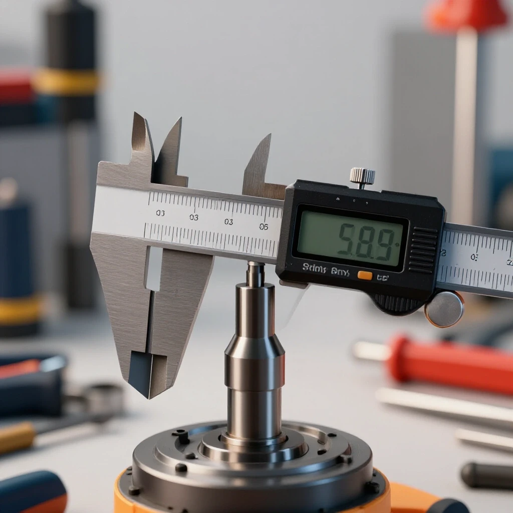
In fabrication, we talk about “run-out” or “backlash”—the amount of unwanted movement in a shaft. For a high-speed grinder, you should have almost zero perceptible side-to-side play.
- Radial Play: Grab the spindle and try to wiggle it side-to-side. If you feel a “click,” the bearing race is worn. This causes tool chatter that ruins weld prep.
- Axial Play: Push and pull the spindle in and out. A tiny amount is normal for gear clearance, but anything over 0.005 inches will cause the gears to “climb” each other, leading to chipped teeth.
- Sound Check: A “gritty” feel when turning the shaft by hand is a sign of “spalling.” This is when the hardened surface of the bearing balls starts to flake off.
If you find a bad bearing, don’t just grease it. Bearings in these tools are usually “sealed for life.” Once they start making noise, the internal geometry is compromised. Replacing a $10 bearing today saves you from buying a $150 motor tomorrow.
Troubleshooting the Trigger Switch and Power Delivery
The switch is a mechanical bridge that completes the circuit; it is frequently clogged by the very metallic dust the tool creates.
When a tool is completely dead—no hum, no sparks, no heat—the problem is usually in the “delivery” phase. Metalworking environments are brutal on switches. Conductive grinding dust gets inside the switch housing and causes “tracking,” where electricity jumps across the contacts and eventually welds them shut or burns them out.
Testing the “Path of Power”
I use a simple bypass test to isolate the switch. After ensuring the tool is unplugged, use your multimeter to check for continuity across the switch pins when the trigger is pulled.
- Check the Cord: Most cord failures happen within six inches of the handle or the plug. Give the cord a “stress test” by wiggling it while checking for continuity. If the Ohms jump around, the internal copper strands are fractured.
- Switch Resistance: A good switch should have near-zero resistance. If you see 5 or 10 Ohms, the internal contacts are carbon-crusted. This resistance creates heat right under your finger.
- Terminal Connections: Vibration is the enemy of tight screws. Check the spade connectors where the cord meets the switch. I have seen many “broken” tools fixed simply by crimping a loose connector back onto its tab.
Resolving Tool Chatter and Harmonic Vibrations
Tool chatter is a resonant vibration caused by an imbalance in the rotating assembly or a misalignment in the gear set.
In my years of troubleshooting, I’ve found that many fabricators ignore “chatter” until it breaks the tool. But chatter isn’t just annoying; it’s a symptom of a machine fighting itself. In a grinder, this usually stems from the “mating” of the pinion gear (on the motor) and the ring gear (on the spindle).
Gear Lash and Alignment
If you’ve ever set up a differential in a truck, you know about “gear lash.” In a grinder, the gears need a specific gap—usually around 0.002 to 0.004 inches.
- Too Tight: The motor will growl and the gear housing will become too hot to touch within 60 seconds.
- Too Loose: You will hear a “clunk” when you start or stop the tool. This causes the teeth to slam into each other, creating harmonics that can shatter a grinding disc.
To check this, I use a tiny dab of “gear marking compound” or even a Sharpie on the teeth. Spin the gears by hand and look at the wear pattern. The mark should be centered on the tooth. If it’s only hitting the edges, your spindle is misaligned, likely due to a crushed bearing seat in the plastic housing.
Real-World Case Study: The “Surging” Grinder
I once consulted for a shop where a 6-inch grinder was “surging”—the RPM would dip and then spike. The operator thought it was a faulty variable speed controller. We followed the diagnostic tree:
- Observation: The surging happened only when the tool was tilted at a 45-degree angle.
- Isolation: We bypassed the speed controller; the surging continued. This ruled out the electronics.
- Mechanical Check: We pulled the brushes. One brush was slightly shorter, but more importantly, the spring was “lazy.”
- The Root Cause: When the tool was tilted, gravity pulled the brush away from the commutator just enough to break contact. The motor would slow down, the brush would drop back, and the motor would “surge” as it regained power.
- The Fix: A new set of brush springs (cost: $2.00) and the tool was back in the rotation.
Comprehensive Diagnostic Checklist for Motor Repair
Use this checklist to maintain a systematic approach during your next repair. Do not skip steps, as the most obvious solution is often hidden by a secondary symptom.
- Visual Inspection: Check cord for nicks, plug for bent prongs, and vents for clogs.
- Manual Rotation: Spin the spindle. Feel for “notches” (bearing) or “rubbing” (armature dragging on field).
- Brush Check: Remove caps. Verify length (>1/4″) and spring tension.
- Continuity Test: Test cord, switch, and field coils.
- Armature Test: Check commutator bars for consistent resistance (<1 Ohm).
- Ground Test: Ensure no part of the electrical circuit touches the metal frame.
- Gear Inspection: Open the gear case. Check for “metal flake” in the grease.
- Reassembly & Load Test: Reassemble and run at “no load” for 2 minutes to seat brushes.
Advanced Metrics and Troubleshooting Values
When you are deep in a diagnostic, having “known-good” values is essential. While every brand differs slightly, most industrial-grade universal motors fall into these ranges.
| Component | Measurement Type | Target Value |
|---|---|---|
| Power Cord | Resistance (End-to-End) | < 0.5 Ohms |
| Field Coils | Resistance | 1.0 – 5.0 Ohms (Balanced) |
| Armature | Bar-to-Bar Resistance | 0.2 – 0.6 Ohms |
| Insulation | Resistance to Ground | Infinite (OL) |
| Brush Length | Minimum Wear Limit | 0.25 Inches (6.35mm) |
| Spindle Play | Radial Run-out | < 0.003 Inches |
Avoiding Common Pitfalls in DIY Motor Repair
One of the biggest mistakes I see intermediate fabricators make is over-lubricating the gear housing. They think “more grease is better,” but too much grease creates “hydraulic lock.” This makes the motor work harder to “churn” the grease, leading to overheating. Only fill the gear cavity about 50% to 60% full.
Another common error is using “generic” brushes. While they might fit the hole, the “grade” of carbon matters. Some brushes are too hard and will eat your copper commutator; others are too soft and will clog the motor with carbon dust in a week. Always try to match the OEM carbon grade.
Finally, never “clean” a motor with compressed air while the brushes are in. You will blow metallic grinding dust directly into the brush holders, which can cause a short circuit the next time you pull the trigger. Always pull the brushes first, then blow out the motor from the rear toward the front.
Mastering the “Feel” of the Repair
As you gain experience, you’ll start to “feel” the health of the tool. A well-repaired motor has a specific “zip” to its sound. It reaches full RPM almost instantly and stops smoothly without excessive “clacking.”
If you finish a repair and the tool still feels “vague” or “mushy” in its power delivery, go back to the commutator. Often, a thin layer of “carbon tracking” (a burnt film) develops between the copper bars. I use a small scribe to gently scrape the “mica” (the slots between the bars) to ensure no conductive dust is bridging them. It’s a tedious 10-minute job, but it’s the difference between a tool that lasts a month and one that lasts another five years.
Frequently Asked Questions
Why does my grinder spark so much after I put in new brushes? New brushes have a flat face, while your commutator is curved. There is very little surface contact at first, which causes arcing. Run the tool at no-load for 2 to 5 minutes to “seat” the brushes to the curve of the commutator.
Can I use sandpaper to clean the commutator? Yes, but use only fine-grit (400-600) non-conductive sandpaper. Never use emery cloth, as it contains metallic particles that can short out the commutator bars.
My grinder runs, but it has no power when I touch the metal. Why? This is usually a “shorted winding” in the armature. The motor can spin without a load, but it lacks the magnetic strength to maintain torque. Check the armature resistance.
How do I know if the field coils are bad? Test the resistance of both coils. They should be nearly identical (within 5%). If one is 2 Ohms and the other is 5 Ohms, the 2-Ohm coil has an internal short.
Why is the gear housing getting hot so fast? This is usually caused by “gear lash” being too tight or the grease having dried out. Old grease turns into a waxy solid that doesn’t lubricate. Clean it out and replace it with high-temp EP (Extreme Pressure) grease.
Is it worth fixing a grinder with a burnt armature? On high-end industrial brands, yes. On entry-level “disposable” tools, the cost of the armature is often 70% of the cost of a new tool. Check the parts price before committing.
What causes a switch to fail intermittently? Metallic dust is the primary culprit. It gets into the mechanical slide of the switch. Sometimes a blast of “electronic contact cleaner” can fix it, but usually, the internal contacts are pitted and need replacement.
How can I tell if a bearing is bad without taking it out? Remove the brushes and spin the spindle. If you hear a “rumble” or feel a vibration in the handle as it slows down, the bearings are failing.
What is “back-EMF” and why does it matter? Back-Electromotive Force is the voltage the motor creates as it spins, which “fights” the incoming voltage. If your windings are damaged, back-EMF drops, causing the motor to draw too much current and burn out.
Can a bad cord cause the motor to burn out? Yes. If the cord has a high resistance due to broken strands, the voltage at the motor drops. Low voltage causes high amperage, and high amperage creates the heat that melts motor insulation.
How do I remove a stuck bearing from the armature shaft? Use a small “two-jaw” or “three-jaw” puller. Never hammer on the end of the armature shaft, as you will “mushroom” the metal and make it impossible to get the new bearing on.
What should I do if I see smoke coming from the vents? Unplug it immediately. Smoke means the resin insulation on the wires is melting. If you catch it fast enough, you might just have a bad connection, but usually, smoke indicates a terminal failure of the windings.
(This article was written by one of our staff writers, Paul Whitaker. Visit our Meet the Team page to learn more about the author and their expertise.)