How to Weld an Industrial Steel Frame Office Desk (DIY Plan)
The smell of sulfur and old gear oil is a permanent fixture in my shop. Over the last 18 years, I have pulled dozens of machines from the brink of the scrap heap. There is a specific kind of silence that surrounds a seized 1940s South Bend lathe or a rusted Buffalo Forge drill press. It is the silence of a tool that has lost its purpose. My job, and perhaps yours, is to find the voice of that machine again. To do that, you need more than just a set of wrenches; you need a workspace that can handle the literal weight of history.
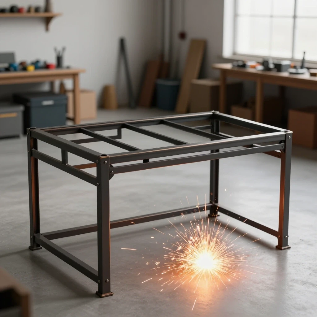
When I first started restoring heavy cast-iron equipment, I made the mistake of using a standard workbench. Within three months, the weight of a disassembled milling head had bowed the surface so badly that my precision levels were useless. I realized then that a restorer’s primary tool is the surface they work on. Building a heavy-duty, load-bearing steel frame for your workspace is not just a DIY project; it is an exercise in industrial engineering. It requires the same patience as scraping a bedway or pouring a babbitt bearing. You have to account for vibration, dead weight, and the absolute necessity of a perfectly level plane.
Assessing Material Integrity for Heavy-Duty Frameworks
Evaluating the structural viability of square and rectangular steel tubing ensures it can support the weight of vintage machinery or heavy shop equipment without failing.
Before you strike an arc, you must understand the metal you are working with. In my experience, many restorers try to save money by scavenging steel from old trailers or scrap yards. While I applaud the thrift, you must be wary of structural fatigue. I once spent a week building a frame from salvaged 2-inch square tubing, only to find that the internal walls had thinned due to hidden “blooming” rust. This occurs when moisture stays trapped inside the tube, eating the metal from the inside out.
When selecting your steel, aim for a wall thickness of at least 1/8 inch (11 gauge) for general use, or 3/16 inch if you plan on mounting a heavy vise or a small benchtop lathe. Rectangular tubing, such as 2×4 inch sections, offers superior resistance to bending when used for the long spans of the frame. Square tubing is excellent for legs and vertical supports because it handles compression loads evenly across all four walls.
Identifying Structural Fatigue and Surface Corrosion
Distinguishing between superficial “flash” rust and deep pitting helps you decide if a piece of steel can still handle a load-bearing role in your shop.
Surface rust is rarely a dealbreaker, but deep pitting is a warning sign. If you find pits that exceed 25% of the wall thickness, that steel is no longer suitable for a primary structural member. I use a simple “hammer test” on salvaged steel. A sharp, high-pitched “ping” indicates solid metal. A dull “thud” often suggests internal scaling or thinning.
Building on this, you must also look for “bowing” in used stock. A piece of steel that has been sitting under a heavy load for twenty years can develop a permanent set. In the world of machinery restoration, we deal in thousandths of an inch. If your base frame starts with a 1/8-inch bow, your machine tool will never be properly calibrated.
| Rust Removal Method | Efficiency | Best For | Risk Level |
|---|---|---|---|
| Wire Wheel | Moderate | Surface rust, flash scale | Low (dust inhalation) |
| Sandblasting | High | Deep pits, complex joints | Moderate (surface etching) |
| Electrolysis | Very High | Internal cavities, small parts | Low (hydrogen gas) |
| Phosphoric Acid | Moderate | Chemical conversion, priming | Moderate (skin irritation) |
Engineering the Foundation: Planning a Stable Steel Workspace
Designing a rectangular steel structure with appropriate bracing prevents racking and ensures a level surface for precision work.
A workspace for a machinery restorer is different from a standard office desk. It must resist “racking,” which is the tendency of a frame to tilt or wobble under lateral force. When you are pulling a 36-inch pipe wrench to break a seized spindle nut, you are applying hundreds of foot-pounds of torque. If your frame isn’t braced, it will move.
Interestingly, the most stable designs I have seen are based on pre-war machine pedestals. These often used a wide footprint with low centers of gravity. I design my frames with a “H-frame” or “X-frame” cross-brace on the back and sides. This triangulation turns a simple rectangle into a rigid box. Without this, the weight of a cast-iron bandsaw could cause the legs to splay over time.
Calculating Load Distribution for Industrial Surfaces
Determining the wall thickness and dimensions of steel tubing required to support heavy cast iron tools prevents deflection and structural failure.
I always calculate for a “static load” plus a 50% “dynamic load” buffer. If your vintage drill press weighs 400 pounds, build the frame to support 600. This accounts for the vibration and the force you apply while using the tool. For a standard 60-inch span, 2×3 inch rectangular tubing with a 3/16-inch wall is my go-to choice.
As a result of these calculations, you must also consider the “point loads.” If the feet of your machine sit in the middle of a span rather than over the legs, the steel will deflect. I solve this by welding “sub-frames” or stiffeners directly under the mounting points of the machine. This ensures the force travels straight down the vertical legs to the floor.
Precision Cutting and Fit-Up for Square Joint Geometry
The process of accurately measuring and cutting steel components ensures 90-degree corners and tight gaps for optimal welding penetration.
In my early years, I was sloppy with my cuts. I thought a 1/16-inch gap could just be filled with weld. While that is true, it leads to massive heat distortion. As the weld cools, it shrinks, pulling the frame out of square. Now, I aim for a “light-tight” fit. This means when two pieces of steel meet, no light should pass through the joint.
I use a cold saw or a high-quality abrasive chop saw for my cuts. If you are using a hand-held angle grinder, you must use a square to check every face. A 1-degree error at the joint can result in a 1/2-inch deviation at the end of a 30-inch leg. For machinery restoration, where we often use precision levels that can detect a 0.0005-inch rise over 10 inches, this kind of error is unacceptable.
- Measure twice, then measure again. Steel doesn’t stretch.
- Use a magnetic square to hold pieces in place during the initial tack weld.
- Deburr every edge. A small burr can throw off your alignment by several degrees.
- Check for squareness by measuring diagonals. If the two diagonal measurements are identical, the frame is square.
Welding Techniques for Rigid Tool Support Structures
Utilizing MIG or TIG welding processes creates high-strength bonds between steel sections, focusing on penetration and heat management.
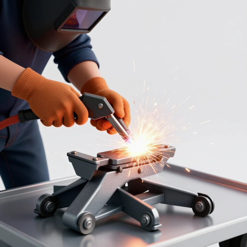
For most shop frames, MIG (Metal Inert Gas) welding is the most efficient choice. It provides deep penetration and is relatively easy to master. However, if you are working on a frame that requires aesthetic precision or very thin-walled tubing, TIG (Tungsten Inert Gas) allows for better heat control.
When I am welding a heavy frame, I focus on “root penetration.” This means the weld must melt into the very heart of the steel thickness. If you only have a “cold” weld sitting on the surface, the vibration from a running machine can eventually crack the joint. I typically set my welder to a higher voltage than the manual suggests for a given thickness to ensure the puddle “bites” into the base metal.
Managing Heat Distortion in Long Steel Spans
Controlling the expansion and contraction of metal during the welding process keeps the frame flat and true throughout the fabrication.
Heat is the enemy of precision. When you weld one side of a joint, the metal expands. As it cools, it contracts more than it expanded, pulling the metal toward the weld. To counter this, I use a “staggered” welding sequence. I never weld a full joint in one pass. Instead, I place small tacks on all four corners of the frame.
Building on this, I weld in short 1-inch beads, moving from one corner of the frame to the opposite corner. This allows the heat to dissipate evenly. If you weld the entire left side and then the entire right side, you will end up with a frame that looks like a banana. I also use “clamping jigs”—heavy pieces of scrap steel clamped to the frame to act as a heat sink and mechanical restraint.
Surface Preparation and Industrial Finishing
Cleaning the welded steel frame of slag, spatter, and oils before applying a durable finish prevents future oxidation and maintains a professional shop appearance.
Once the welding is done, the work of a restorer really begins. A raw steel frame will start to rust within hours in a humid shop. I start by using a flap disc on an angle grinder to smooth out the welds. I don’t grind them flush unless it’s necessary for a mounting surface, as the “hump” of the weld provides structural strength.
After grinding, I use a degreaser to remove the thin film of oil that comes on new steel. For a finish, I prefer an industrial-grade epoxy paint or a “hammered” finish. These are durable enough to resist the chips and oils common in a metalworking environment. If you want a truly “industrial” look that matches vintage machines, look for “machinery gray” or “vista green” paints, which were the standards for decades.
| Feature | MIG Welding | TIG Welding |
|---|---|---|
| Speed | Fast | Slow |
| Ease of Use | High | Moderate/Low |
| Heat Input | High | Controlled |
| Cleanliness | Moderate (spatter) | Very High |
| Structural Strength | Excellent | Excellent |
Case Study: The 1938 Lathe Bench Restoration
A few years ago, I rescued a 1938 Hendey lathe. The original cast-iron legs were missing, so I had to fabricate a new steel framework. I chose 3-inch square tubing with a 1/4-inch wall. The challenge was the weight; the lathe headstock alone weighed 600 pounds.
I used a “box-in-box” design. I built two identical rectangular frames and connected them with heavy cross-members. To ensure the lathe bed wouldn’t twist, I welded 1-inch thick steel pads to the top of the frame. I then used a process called “hand scraping” to make these pads perfectly co-planar.
Hand scraping is the art of using a carbide-tipped tool to shave off high spots on metal, guided by a precision surface plate and “engineer’s blue” dye. I aimed for 15 “points per inch” (PPI). This level of precision ensured that when I bolted the lathe down, the bed remained straight to within 0.001 inches over its entire length. This project taught me that the frame isn’t just a stand; it’s a part of the machine’s geometry.
Integrating Precision Leveling and Vibration Dampening
A heavy-duty frame is only as good as its contact with the floor. Most shop floors are not flat. If your frame sits on four points, one of them will almost certainly be “floating.” This causes the frame to vibrate and can even lead to a “twist” in the structure.
I always weld heavy-duty threaded bungs into the bottom of the legs. I then use 3/4-inch diameter leveling feet. This allows me to use a machinist’s level (which can detect a 0.0005-inch rise) to get the workspace perfectly flat. For machines that produce high vibration, like a reciprocating saw or a large grinder, I use “isomount” pads—rubber and steel sandwiches that soak up the energy before it reaches the floor.
- Bungs: Use thick-walled threaded inserts rather than just welding a nut to the bottom of the tube.
- Thread Pitch: I prefer 3/4-10 (UNC) for leveling feet. It’s a standard pattern and easy to source.
- Vibration: If the frame “rings” like a bell when hit, fill the legs with dry sand. This kills the resonance.
Strategies for Sourcing Obsolete Fasteners and Hardware
When building a frame to support vintage gear, you will often run into “legacy” thread patterns. Pre-1950s machinery often used threads that are no longer common in big-box stores. For example, you might find 1/2-12 threads instead of the modern 1/2-13.
I keep a “thread pitch gauge” in my pocket at all times. If I need to bolt a machine to my new steel frame, I verify the thread before I drill. If the thread is obsolete, I have two choices: find a specialty supplier like McMaster-Carr or, more often, I use my lathe to cut the bolt myself. This is where the skill of a restorer pays off. Being able to “single-point” a thread on a lathe allows you to create custom fasteners that match the historical integrity of the machine you are mounting.
Final Alignment and Tolerance Testing
Once the frame is welded, painted, and leveled, it’s time for the final “stress test.” I place the heaviest component of the machine on the frame and check for deflection. I use a dial indicator mounted on a magnetic base. If the frame sags more than 0.005 inches, I know I need to add more bracing.
Restoring a machine is a journey of a thousand small measurements. Your workspace frame is the first and most important measurement. It provides the “datum” or the zero point from which all other work flows. If your base is solid, square, and level, the rest of the restoration will fall into place. If it’s weak or twisted, you will be fighting the machine every step of the way.
- Leveling: Use a 12-inch machinist level on the long and short axes.
- Squareness Check: Re-verify diagonals after the frame has fully cooled.
- Vibration Test: Run a small motor on the surface and feel for “dead spots” or resonance.
- Load Test: Apply the maximum expected weight and measure deflection at the center point.
Conclusion
Building a high-strength steel support structure is the foundation of any successful machinery rescue. It requires a shift in mindset from “making a desk” to “engineering a machine base.” By selecting the right wall thickness, managing your welding heat, and insisting on precision leveling, you create a workspace that will last as long as the vintage tools you put on it.
The next time you find a rusted, seized piece of cast iron in a scrap yard, you won’t just see a project. You’ll see a machine that deserves a solid place to stand. Start by mapping out your steel cuts, cleaning your joints to a bright finish, and taking the time to weld with deep penetration. Your future self, and the machines you save, will thank you.
FAQ
What is the best steel tubing size for a heavy machine stand? For most restoration work involving tools up to 500 lbs, 2×3 inch or 3×3 inch tubing with a 3/16-inch wall thickness is the “sweet spot.” It offers excellent rigidity without being impossibly heavy to move.
Should I use MIG or TIG welding for my frame? MIG is generally better for structural frames because it is faster and provides great penetration on 3/16-inch steel. TIG is better if you are using thinner materials or want a “show-quality” finish without grinding.
How do I stop my frame from warping while I weld? Use the “tack and move” method. Tack all joints first, then weld in short 1-inch increments, jumping from one side of the frame to the other to keep heat distribution even.
Can I use salvaged steel for a precision workspace? Yes, but you must check for internal rust and straightness. Use a straightedge to ensure the tubing hasn’t “taken a set” or bowed from previous loads.
How do I level a frame on an uneven concrete floor? Welding threaded inserts (bungs) into the legs allows you to use heavy-duty leveling feet. This is essential for keeping machine tools like lathes or mills within factory tolerances.
Why is my frame vibrating so much when the machine is running? This is likely due to “resonance.” You can dampen this by filling the hollow steel legs with dry sand or using rubber vibration-isolating pads under the machine’s feet.
What paint is best for an industrial steel frame? An industrial epoxy or a “hammered” finish paint is best. These are resistant to the oils, coolants, and metal chips that are part of the daily life of a machinery restorer.
Do I really need to use a machinist’s level? If you are mounting a lathe or a mill, yes. A standard carpenter’s level is not accurate enough to detect the minute twists that can ruin a machine’s precision.
How do I calculate the weight my frame can hold? A general rule for 3/16-inch wall 2×3 tubing is that it can support several thousand pounds in compression (vertically). The limit is usually “deflection” (sagging) in the horizontal spans. Keep spans under 48 inches or add center legs.
What should I do if I find deep pits in my steel? If the pits are deeper than 1/4 of the metal’s thickness, do not use that section for a primary load-bearing leg. Use it for non-structural bracing instead.
(This article was written by one of our staff writers, Richard Beaumont. Visit our Meet the Team page to learn more about the author and their expertise.)