How to Rebuild a Vintage Drill Press Quill Assembly (Fix)
When I first walked into a damp basement in 2006 to look at a 1940s Walker-Turner drill press, I didn’t see a tool. I saw a frozen column of rust and a spindle that wouldn’t budge even with a deadblow hammer. Over the last 18 years and 40 restorations, I have learned that these old machines are not just scrap metal; they are masterpieces of mechanical engineering waiting for a second life. Restoring classic cast iron requires more than just a wrench; it demands a blend of patience, technical precision, and a deep respect for the tolerances established by long-defunct manufacturers.

The heart of any drill press is the vertical sliding mechanism that carries the rotating spindle. When this part of the machine becomes gritty, loose, or seized, the tool loses its primary purpose: accuracy. Bringing a neglected machine back to factory specifications is a journey through time. It involves navigating obsolete thread patterns, managing heavy structural components, and often fabricating what can no longer be bought. My goal is to guide you through the process of reviving this critical assembly so your machine can once again drill a hole within a thousandth of an inch.
Evaluating the Vertical Feed and Spindle Housing
Before turning a single bolt, you must assess the structural integrity and mechanical condition of the sliding sleeve and its housing. This stage determines if the machine is a candidate for a full restoration or if it will serve better as a parts donor for a future project.
I always start by checking for “quill slop,” which is the lateral movement of the sleeve within the head casting. If you extend the sleeve halfway and can feel a distinct “clunk” when pushing it side-to-side, you are looking at significant wear. I use a dial indicator mounted to the table to measure this movement. A reading of 0.005 inches or more usually indicates that the bore is worn or the sleeve has lost its diameter. While this can be fixed with hand scraping or boring and sleeving, it adds a layer of complexity to the project.
Mapping the Disassembly Sequence
A disassembly map is a visual or written record of every fastener, spring, and spacer in the order they are removed from the machine. This documentation prevents the “bucket of bolts” syndrome where a restorer forgets the orientation of a critical internal shim months after the initial teardown.
I use a digital camera to document every angle before I touch a tool. For vintage machinery restoration, I also keep a dedicated notebook where I sketch the orientation of the return spring housing and the depth stop mechanism. Many pre-war machines used proprietary thread pitches that look like standard National Coarse or Fine but are slightly different. I always measure the threads with a pitch gauge and note them in my log. If I lose a screw from a 1930s Buffalo Forge press, I may have to turn a new one on a lathe because a hardware store replacement simply won’t fit.
| Component | Common Issue | Inspection Method |
|---|---|---|
| Spindle Sleeve | Scoring or Galling | Visual check for deep vertical scratches |
| Return Spring | Fatigue or Snapping | Test tension during the last inch of travel |
| Spindle Bearings | Pitting or Noise | Rotate by hand; feel for “notchy” spots |
| Rack Teeth | Chipped or Flattened | Inspect the gear teeth on the back of the sleeve |
Strategic Disassembly of Seized Cast Iron Components
Removing machinery rust is only half the battle; the real challenge is separating parts that have been chemically bonded by oxidation for fifty years. Using brute force on vintage cast iron is the fastest way to turn a restoration into a tragedy, as old castings are brittle and prone to cracking under impact.
I rely on a “thermal release plan” for stubborn parts. This involves a cycle of penetrating oil, localized heat, and vibration. I prefer using a 50/50 mix of Acetone and Automatic Transmission Fluid (ATF) as a penetrant. It out-performs many commercial sprays in my experience. I apply the mixture and let it sit for 24 to 48 hours. If the part remains stuck, I use a propane torch to heat the outer casting. The goal is to expand the housing slightly while keeping the internal sleeve cool, breaking the rust seal.
Why Seized Cast Iron Screws Crack Under Force
Cast iron has excellent compressive strength but very poor tensile strength, meaning it can support a heavy load but snaps easily if you try to “pull” or “twist” it too hard. When a steel screw is rusted into a cast iron head, the rust occupies more volume than the original metal, creating immense internal pressure.
When I encounter a frozen set screw, I never use a standard screwdriver. I use a manual impact driver that converts a hammer blow into a high-torque twisting motion. This “shocks” the threads loose without the sustained torque that snaps screw heads. If the screw head is already mangled, I move to drilling it out. I use a left-hand drill bit; frequently, the heat and vibration from the drilling process will catch the screw and back it out naturally. This preserves the original threads in the casting, which is vital when dealing with obsolete fastener patterns.
Stripping Decades of Corrosion Without Damaging Base Metal
Once the assembly is apart, you are faced with layers of “shop crust”—a mixture of dried organic oils, metal chips, and deep-seated rust. The objective is to remove this debris down to the bare metal without removing the actual material, which would change the fit and tolerances of the machine.
For heavy structural corrosion, I avoid using aggressive wire wheels on a bench grinder for precision surfaces. A wire wheel can round off sharp edges that are critical for mechanical alignment. Instead, I use chemical chelators or electrolysis. Chelators like Evapo-Rust are non-toxic and specifically target iron oxide, leaving the base steel or iron untouched. I submerge the spindle sleeve and internal components in a bath for 12 to 24 hours. When they come out, the rust is gone, leaving a gray, phosphate-like finish that is ready for polishing.
Setting Up an Electrolysis Bath for Large Castings
Electrolysis is a process that uses a low-voltage DC power supply to pull rust off a part and onto a sacrificial “anode.” It is particularly effective for large, complex castings like the drill press head where manual scrubbing is impossible.
I use a manual 12V battery charger and a plastic tub filled with water and washing soda (sodium carbonate). The part to be cleaned is connected to the negative terminal, while a piece of scrap steel (the anode) is connected to the positive terminal. It is critical to never use stainless steel for the anode, as it produces toxic hexavalent chromium. I usually run the bath at 2 to 4 amps. After 12 hours, the rust has turned into a black sludge that can be easily washed away with a nylon brush. This method is the safest way to clean internal bores without changing the dimensions of the metal.
| Method | Best For | Pros | Cons |
|---|---|---|---|
| Chelators (Evapo-Rust) | Precision parts, sleeves | No metal loss, safe | Can be expensive for large baths |
| Electrolysis | Large castings, heads | Very cheap, reaches crevices | Requires power setup, messy |
| Scouring Pads (WD-40) | Light surface rust | Fast, easy to control | Can be labor-intensive |
| Wire Wheels | Non-precision surfaces | Extremely fast | Can damage edges/fine threads |
Restoring the Spindle Sleeve and Internal Bearings
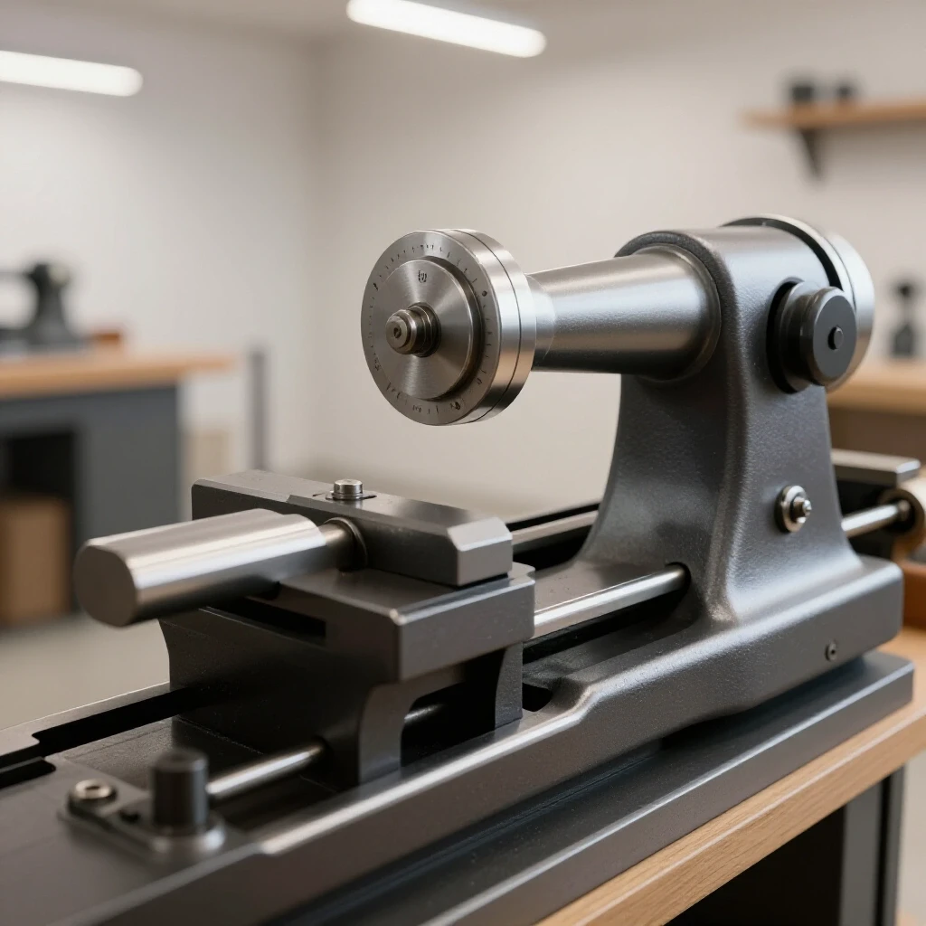
The spindle sleeve, or quill, is the heart of the vertical feed. It houses the spindle and the bearings that allow it to spin at high speeds. In classic tool alignment, the goal is to achieve near-zero runout, meaning the spindle should rotate perfectly on its center axis without wobbling.
I begin by inspecting the spindle itself. I place it between centers on a lathe or on V-blocks and use a dial indicator to check for straightness. If the spindle is bent more than 0.002 inches, it will cause vibration and poor hole quality. For minor bends, I have had success using a hydraulic press to gently “nudge” it back into alignment. However, this is a delicate process that requires frequent checking. If the spindle is straight, I move on to the bearings.
Servicing Legacy Bearings and Bushings
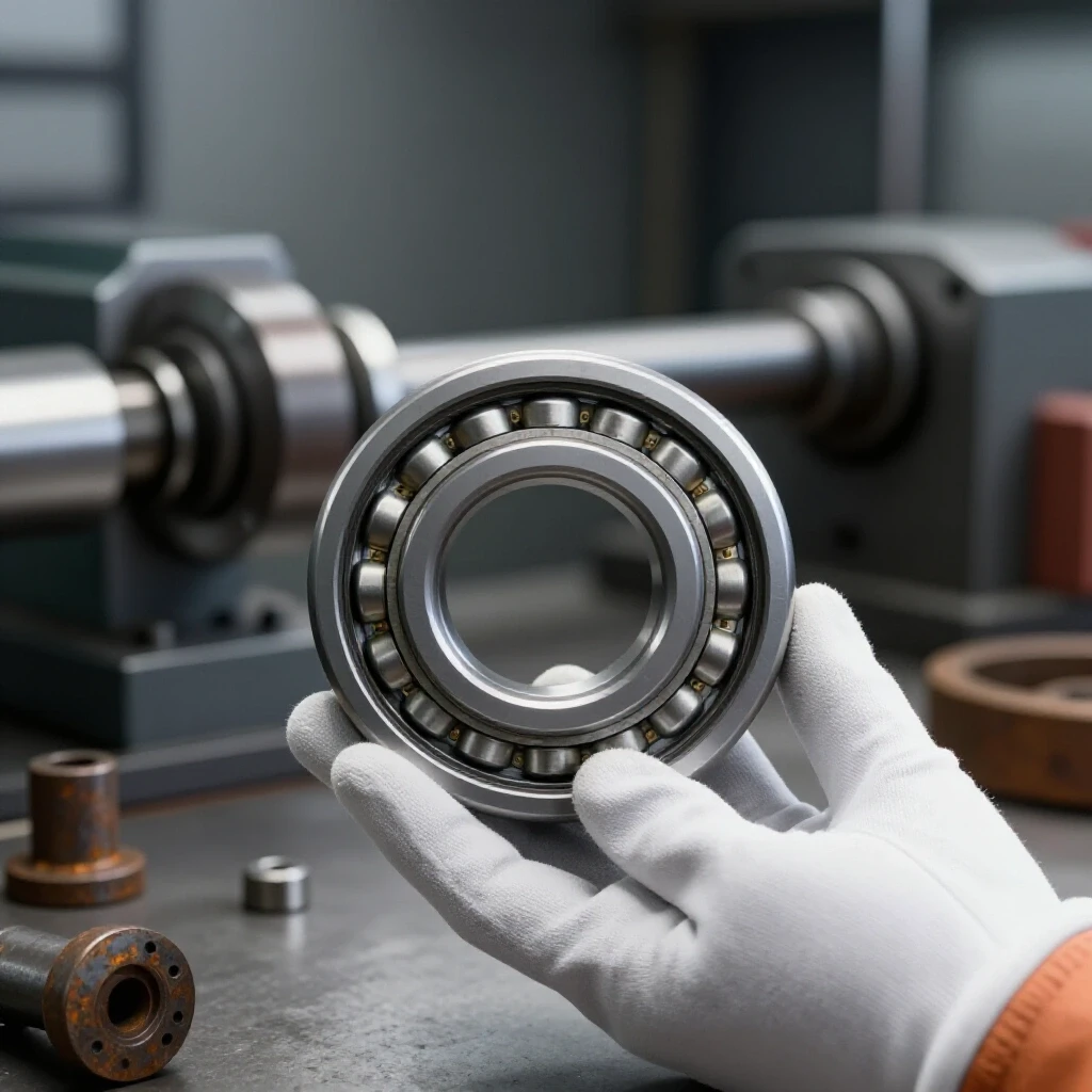
Older drill presses often use either deep-groove ball bearings or sleeve bearings (bushings). If the machine uses ball bearings, I almost always replace them with modern, shielded equivalents. Modern bearings are often built to higher tolerances than those available 70 years ago, which immediately improves the machine’s performance.
If the machine uses babbitt or bronze sleeve bearings, the approach is different. Babbitt is a soft white metal alloy used in older machinery to provide a low-friction surface. If the babbitt is worn, I check the clearance. A standard clearance for a spindle sleeve is 0.001 to 0.002 inches. If the gap is larger, you may need to pour new babbitt or machine a new bronze bushing. For bronze bushings, I use a press to remove the old ones and then turn new ones from 660 Bronze on the lathe. I always aim for a “light press fit” into the housing and then ream the internal diameter to fit the spindle perfectly.
- Measure the spindle diameter with a micrometer at three points.
- Measure the internal diameter of the sleeve or bearings.
- Calculate the clearance (ID minus OD).
- If clearance exceeds 0.003″, plan for replacement or adjustment.
- Check for end-play (vertical movement) and address with shims if necessary.
Precision Alignment and Hand Scraping for Smooth Operation
Once the parts are clean and the bearings are serviced, the assembly must fit back into the head casting with a smooth, drag-free motion. If the quill feels tight in some spots and loose in others, the bore or the sleeve may be out of round. This is where machinery hand scraping becomes an essential skill.
Hand scraping is the process of using a flat, hardened steel tool to remove minute amounts of metal (measured in millionths of an inch) to create a perfectly flat or round surface. I use a blue spotting pigment (Prussian Blue) to identify the “high spots” on the sleeve. I apply a very thin layer of blue to the sleeve, slide it into the head, and rotate it. When I pull it out, the blue will have rubbed off onto the high spots of the bore. I then use a scraper to gently remove those spots.
Achieving High-Precision Bearing Points
The goal of scraping is not to make the surface perfectly smooth like a mirror, but to create a series of high points that support the load while leaving “valleys” to hold oil. In the restoration world, we measure this in “Points Per Inch” (PPI).
For a drill press quill, I aim for 10 to 20 PPI. This density ensures that the sleeve is well-supported and won’t vibrate during heavy drilling, but it also ensures that the vertical movement remains fluid. If you scrape a surface too flat, the two metal faces can actually “wring” together, creating a vacuum that makes the quill feel heavy or stuck. I use a precision level and a square to ensure that as I scrape, I am not accidentally tilting the spindle axis away from the table’s 90-degree plane.
- 10 PPI: Suitable for general machinery slides and rougher fits.
- 20 PPI: Standard for high-quality vintage tool restoration.
- 40 PPI: Reserved for precision grinders and master surface plates.
Final Assembly, Preload, and Lubrication Standards
Reassembling the vertical feed is a test of your organizational skills. I start by thoroughly cleaning the internal bore of the head casting with lint-free rags and mineral spirits. Any speck of grit left inside will act as an abrasive and ruin your newly scraped surfaces within minutes of operation.
I apply a thin coat of ISO 68 way oil to the sleeve before sliding it into the housing. Way oil contains “tackifiers” that help it stick to vertical surfaces, preventing it from just draining out the bottom of the machine. For the internal spindle bearings, I use a high-quality electric motor grease or a lighter ISO 32 spindle oil, depending on whether the bearings are sealed or open.
Setting the Proper Bearing Preload
Preload is the amount of pressure applied to the bearings to eliminate internal clearance. If there is too little preload, the spindle will chatter; too much, and the bearings will overheat and fail prematurely.
On most vintage presses, preload is set by a threaded nut at the top of the spindle. I tighten the nut until I feel a slight resistance when spinning the spindle by hand, then back it off just enough so it spins freely but has zero vertical “clunk.” This is a “feel” that comes with experience. I always check the temperature of the bearing housing after running the machine for ten minutes. It should feel warm to the touch (around 100-110°F) but never hot enough to be uncomfortable.
- Slide the spindle into the cleaned sleeve.
- Install the thrust bearings and take-up nuts.
- Adjust preload until vertical play is eliminated.
- Install the return spring and adjust for a snappy but not violent return.
- Lock all set screws using a drop of medium-strength thread locker.
Conclusion
Restoring the vertical movement of a classic drill press is a labor-intensive process that rewards the patient restorer with a tool that often outperforms modern equivalents. By systematically addressing rust, measuring tolerances with precision, and respecting the metallurgy of cast iron, you preserve a piece of industrial history. My 18 years in the shop have taught me that there are no shortcuts to quality. Whether you are scraping a bore or hunting for an obsolete screw, the focus should always be on bringing the machine back to its original factory intent.
The next time you see a rusted, “frozen” machine at a scrap yard, don’t walk away. With the right chemical treatments, a bit of heat, and the willingness to learn the art of hand scraping, you can turn that relic into the centerpiece of your workshop. The satisfaction of feeling a quill slide perfectly through its travel, with zero play and total silence, is why we do this work.
Frequently Asked Questions
How do I know if a vintage machine is too rusted to save?
A machine is generally “too far gone” only if the cast iron has structural cracks or if the rust has pitted the precision bores deeper than 0.010 inches. Surface rust looks terrible but is rarely fatal. If the main casting is sound, almost everything else can be repaired or fabricated.
Can I use a torch to heat the quill housing?
Yes, but use caution. Use a propane or MAPP gas torch rather than oxy-acetylene. You want a “soaking” heat, not a pinpoint melting heat. Move the flame constantly to avoid creating a hot spot that could crack the casting.
What should I do if the return spring is missing?
Many vintage drill press springs are still available as “universal” replacements. Measure the width of the spring steel and the diameter of the housing. If you can’t find a direct fit, you can often adapt a spring from a similar-sized modern press by filing the mounting hook to shape.
Why is my spindle vibrating after I replaced the bearings?
Vibration usually stems from three things: a bent spindle, a pulley that is out of balance, or a bearing that wasn’t seated squarely. Use a dial indicator to check the spindle runout; it should be under 0.001 inches for a high-quality restoration.
Is it necessary to paint the internal parts of the assembly?
No. The internal bore and the sliding sleeve should never be painted. They rely on a metal-to-metal fit with a thin film of oil. Painting these surfaces will cause the machine to seize or operate with extreme friction.
How do I find the correct oil for an old machine?
Avoid automotive oils, as they contain detergents that can suspend grit rather than letting it settle. Use ISO 68 Way Oil for sliding surfaces and ISO 32 Spindle Oil for high-speed rotating parts. These are available from industrial supply houses.
What if I can’t find a replacement for a custom-threaded bolt?
If the thread is obsolete (like some 12-24 or 1/2-12 patterns found on old machines), you have two choices: turn a new bolt on a lathe or tap the hole to the next size up. I always recommend turning a new bolt to preserve the original casting’s integrity.
How much “slop” is acceptable in a drill press quill?
For precision work, you want less than 0.002 inches of lateral movement. If you have more than 0.005 inches, you will struggle to drill accurate holes or use larger bits without the drill “walking” or vibrating.
Can I use sandpaper to remove rust from the spindle?
I don’t recommend it. Sandpaper can easily create “low spots” or make the spindle out-of-round. Use a chemical chelator first, then polish with a very fine (0000) steel wool or a Scotch-Brite pad lubricated with oil.
How do I safely remove a stuck chuck from the spindle?
Most vintage spindles have a Morse Taper. Use a proper “drift key” inserted into the slot in the spindle. If there is no slot, you may need to use a set of “chuck removal wedges” that apply even pressure to the back of the chuck. Never hit the chuck directly with a steel hammer.
(This article was written by one of our staff writers, Richard Beaumont. Visit our Meet the Team page to learn more about the author and their expertise.)