Is Budget Gasless Flux-Core Welding Strong Enough? (Review)
I remember standing in a cold shop three winters ago, staring at a mounting bracket that had just sheared off a utility trailer. The weld looked decent from the outside—a bit of ripple, some slag, but nothing that screamed “failure.” When I put a pry bar to it, the joint popped like a dry twig. That moment changed how I look at entry-level equipment. It wasn’t a failure of the machine itself, but a failure in my diagnostic process. I hadn’t accounted for the variables that dictate whether a self-shielded joint actually holds. In the world of industrial maintenance, we don’t guess. We isolate, we test, and we verify.
Systematic Isolation of Fabrication Errors
A systematic diagnostic framework is the structured process of identifying the root cause of a failure by isolating variables. In the context of welding, this means looking past the surface of the bead to understand how voltage, wire speed, and technique affect the internal structure of the metal. It requires a calm, step-by-step approach to eliminate guesswork.
When a weld fails or looks “off,” the instinct is to start turning knobs. That is the quickest way to get lost. Instead, I use a metalworking diagnostic guide approach. I start by checking the mechanical basics. Is the ground clamp making a solid connection on clean metal? Is the wire tension set correctly? In my experience, 40 percent of weld quality issues with budget setups stem from poor electrical contact or erratic wire feeding rather than the wire chemistry itself.
Controlling Variables in Self-Shielded Processes
Variable control involves keeping every factor constant except for the one you are testing. For gasless flux-core, this includes stick-out length, travel angle, and the cleanliness of the base material. By fixing three of these and changing only one, you can see exactly what is causing your bead to wander or sputter.
I treat a welder like I treat a lathe. If I have tool chatter, I don’t just change the bit. I check the spindle bearings, the tool post rigidity, and the feed rate. With a gasless setup, your “tool” is the wire. If that wire doesn’t exit the tip at a perfectly consistent rate, your weld pool will fluctuate. This fluctuation leads to cold laps and lack of fusion. I always measure my wire stick-out with a physical gauge—usually 3/4 of an inch—to ensure the resistance remains stable during the arc.
Diagnosing Internal Deficiencies in Flux-Cored Beads
Identifying internal flaws requires looking for clues in the cooling slag and the shape of the finished bead. Since we cannot see through the metal without X-ray equipment, we must rely on surface indicators to predict what is happening at the root. This involves analyzing heat tint, penetration depth, and the presence of trapped impurities.
The biggest question I get is whether budget wire can actually penetrate 6mm mild steel. The answer depends on your ability to troubleshoot weld porosity and heat input. If the bead is sitting “on top” of the metal like a caterpillar, you have a lack of fusion. This is often caused by a travel speed that is too fast or a voltage that is too low. I look for a “tie-in” where the edges of the weld melt smoothly into the base plate. If there is a sharp line or a valley at the edge, the joint is weak.
Root Causes of Porosity and Inclusion
Porosity is the presence of small holes or gas pockets within the weld metal, often resembling a sponge. In self-shielded welding, this is usually caused by the atmosphere contaminating the molten pool. Slag inclusion occurs when the non-metallic flux gets trapped inside the weld because the pool cooled too quickly or the angle was wrong.
When I see pinholes in my bead, I immediately check my “drag” angle. Unlike gas-shielded welding where you might push the puddle, gasless wire requires a pull or drag technique. If you push, you trap the gas and slag under the metal. I also check for moisture. Flux-core wire is hygroscopic; it sucks up water from the air. If your wire has been sitting in a damp shop for six months, you will never get a clean weld. I’ve spent hours chasing electrical gremlins only to find out the wire itself was the “broken” part of the system.
Mechanical Feed Integrity and Its Impact on Strength
The mechanical feed system consists of the motor, drive rolls, and liner that move the wire from the spool to the torch. If this system has any “hiccups” or slips, the arc will stutter. This creates a series of micro-starts and stops within a single bead, which are prime locations for structural failure.
In my years of machinery maintenance, I’ve found that “tool chatter” isn’t just for mills. In a wire feeder, chatter happens when the drive rolls are too tight or too loose. If they are too tight, they crush the hollow flux-core wire, turning it into an oval that jams in the contact tip. If they are too loose, the wire slips. I use a simple mechanical troubleshooting step: I pinch the wire between my gloved fingers at the gun. The motor should be able to slip the rolls without stopping. If it jerks, your feed consistency is ruined.
Resolving Wire Surging and Drive Roll Slip
Wire surging is an intermittent change in the speed of the wire, often caused by a worn liner or a failing motor controller. Drive roll slip happens when the friction between the rolls and the wire is insufficient to overcome the resistance in the torch lead. Both issues lead to an unstable arc and poor penetration.
To diagnose this, I look at the “back-EMF” or the load on the motor. On budget machines, the motor is often small. If the torch lead has a sharp kink, the motor works harder, the voltage drops, and the wire slows down. I keep my leads as straight as possible. I also check the alignment of the drive rolls. If the wire doesn’t enter the guide tube perfectly centered, it creates friction that leads to inconsistent beads. A mechanical tolerance of even 0.010 inches of misalignment can cause noticeable surging.
| Factor | Symptom | Diagnostic Check | Fix |
|---|---|---|---|
| Drive Roll Tension | Flattened wire or bird-nesting | Measure wire diameter after rolls | Adjust tension to allow slight slip |
| Contact Tip Wear | Erratic arc or “hunting” | Check for “keyholing” in the tip hole | Replace tip (0.035″ for 0.035″ wire) |
| Liner Friction | Wire surging or stuttering | Pull wire by hand through the lead | Blow out liner with air or replace |
| Ground Quality | Spatter and low heat | Check Ohms between clamp and work | Clean metal to shiny finish |
Practical Shop-Floor Strength Assessments
A shop-floor strength assessment is a non-certified test used to verify that a welding procedure is producing joints that can withstand the intended load. These tests, such as the bend test or the “coupon” break, provide immediate feedback on whether the penetration and fusion are sufficient for the task at hand.
We don’t need a million-dollar lab to see if a budget wire is “strong enough.” I use the 90-degree bend test. I weld two pieces of 6mm steel in a T-joint, then I put it in a heavy vise and hit it with a sledgehammer until it bends 90 degrees. If the weld snaps, I look at the break. If the metal is shiny and smooth where it broke, I had zero penetration. If the metal tore chunks out of the base plate, the weld was stronger than the steel. This is the ultimate metal fabrication fix for a lack of confidence in your equipment.
The 90-Degree Bend Test and Tensile Logic
The 90-degree bend test forces the weld root to stretch. If there are any inclusions or cold starts, the stress will concentrate there and cause a crack. Tensile logic refers to the understanding of how a joint handles pulling forces, ensuring that the weld throat is thick enough to carry the load of the surrounding material.
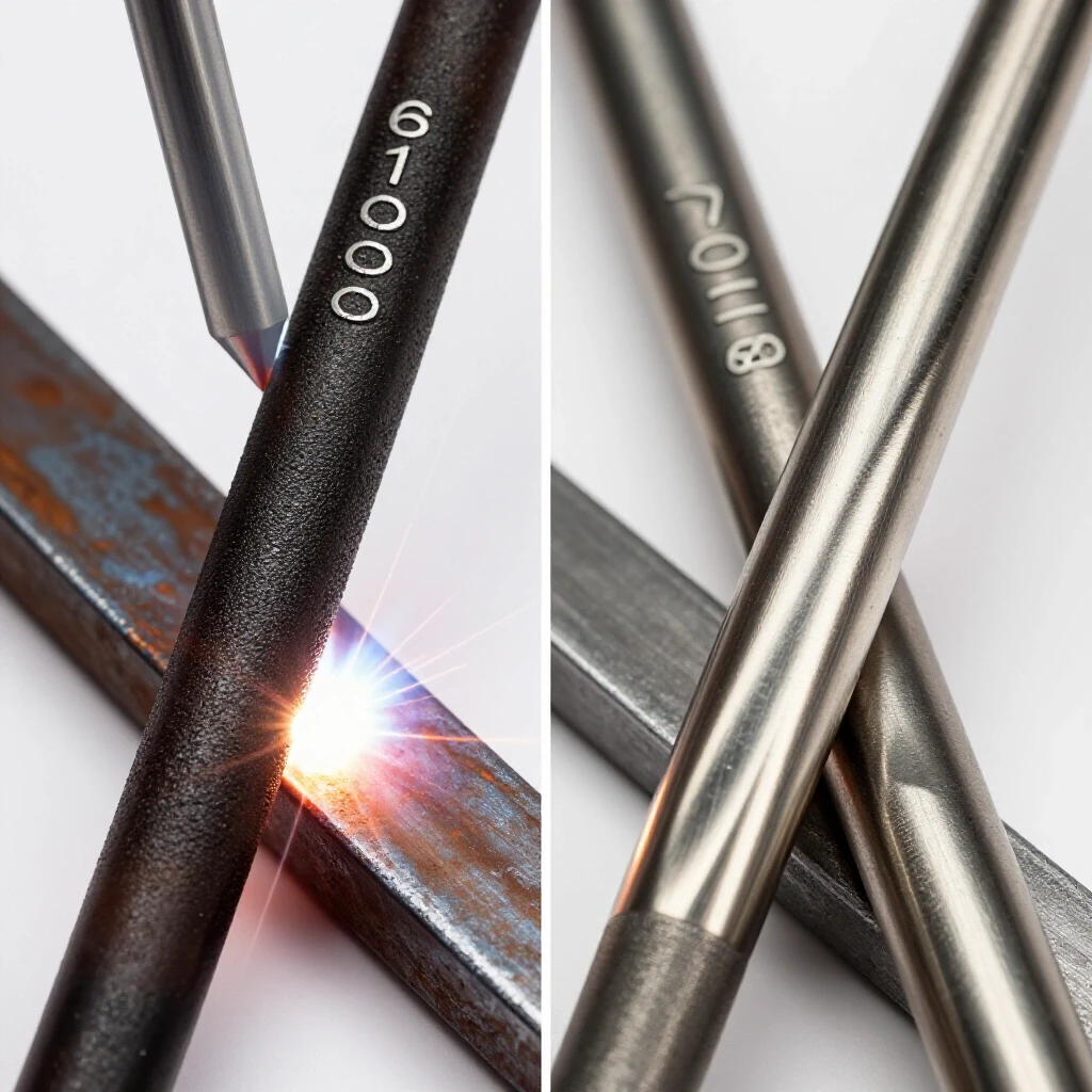
When I perform these tests, I look for “ductility.” A good weld shouldn’t just be hard; it should be able to deform slightly before it breaks. If a gasless weld is too brittle, it might be due to excessive heat or the wrong polarity. Most budget gasless wires require DCEN (Direct Current Electrode Negative). If you have the polarity backward, the weld will be weak, brittle, and full of spatter. I always double-check the internal jumpers on the machine before starting a structural repair.
Troubleshooting Electrical Instability in Budget Machines
Electrical instability refers to the inability of a welding power source to maintain a constant voltage or current during the welding process. This is common in budget machines where the internal capacitors and transformers are sized for light duty. This instability leads to a “cold” arc that fails to melt the base metal properly.
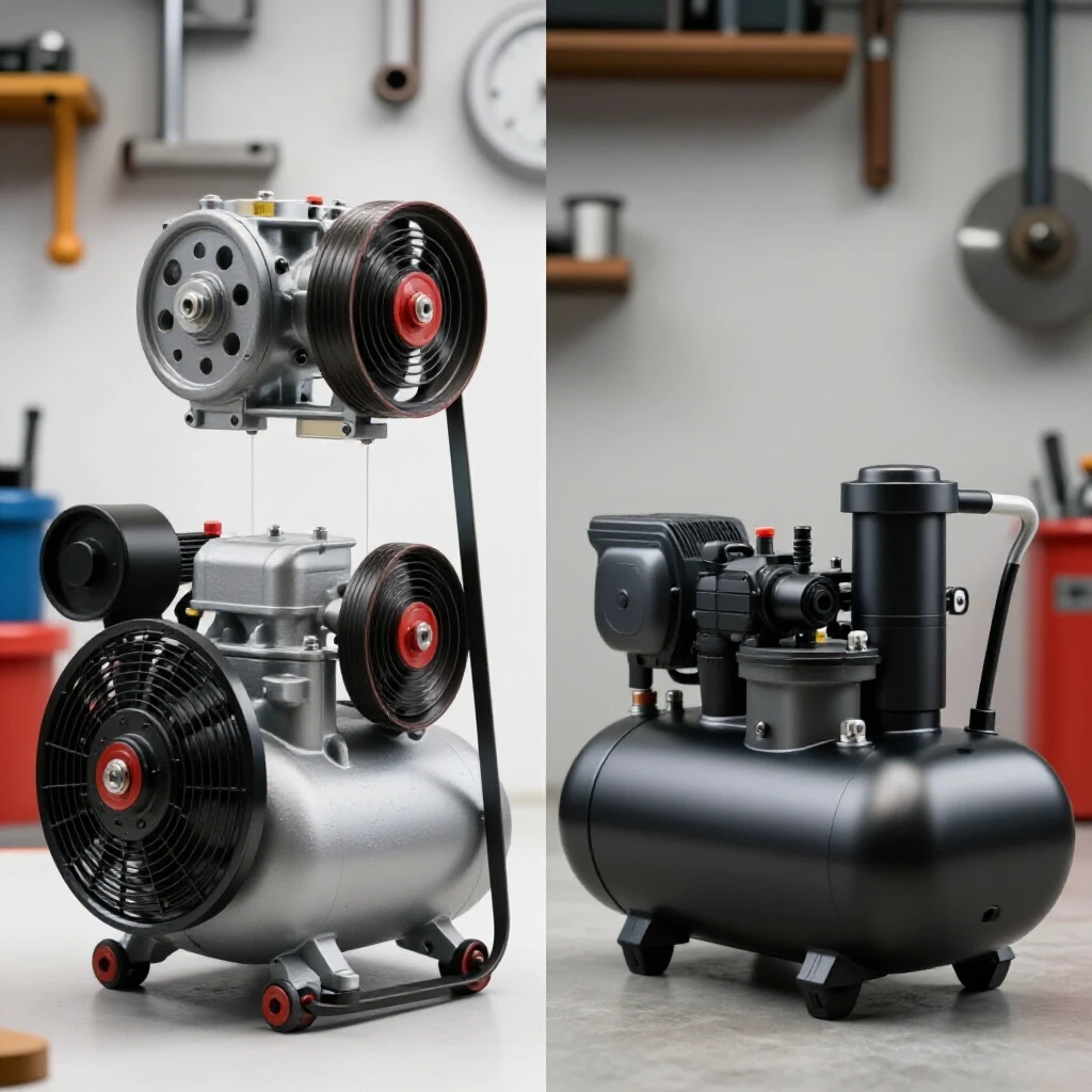
I’ve spent a lot of time tracking down “electrical gremlins” in shop equipment. In one case, a machine was performing poorly every afternoon at 2 PM. It turned out the shop’s air compressor was kicking on, causing a voltage drop on the main line. A budget welder needs every bit of its rated input. If you are running on a 50-foot extension cord that is too thin, your 6mm steel welds will fail. I use a multimeter to check the voltage at the outlet while the arc is struck. If it drops more than 10 percent, the weld strength will suffer.
Voltage Drop and Power Quality Diagnostics
Voltage drop is the reduction in electrical potential as current flows through a conductor. In welding, a drop in voltage directly translates to a loss of heat at the puddle. Power quality diagnostics involve measuring the stability of the incoming electricity to ensure the machine can operate at its peak performance.
To ensure your budget setup is “strong enough,” you must provide it with a “clean” path. I recommend a dedicated 20-amp or 30-amp circuit. If you see the lights dimming when you pull the trigger, your weld penetration is likely fluctuating. I also check the internal connections of the welder. Sometimes, a loose nut on the main transformer can cause a high-resistance point that eats up your welding power. It’s these small mechanical troubleshooting steps that separate a hobbyist from a diagnostic specialist.
Systematic Calibration for Gasless Processes
Calibration is the process of adjusting a machine’s settings to match a known standard of performance. For a welder, this means finding the “sweet spot” where the voltage and wire speed create a stable arc with the correct amount of heat for the thickness of the metal being joined.
I follow a specific “lathe alignment checklist” style of calibration for my welders. I start with the manufacturer’s door chart, but I don’t treat it as gospel. I run “bead on plate” tests on scrap 6mm steel. I adjust the wire speed until the “sizzle” sounds like frying bacon. If it sounds like a machine gun, the wire is too fast. If it’s a lazy pop, it’s too slow. I document these settings in a small notebook. Having a history of what worked on specific thicknesses saves me hours of frustration when a new project hits the bench.
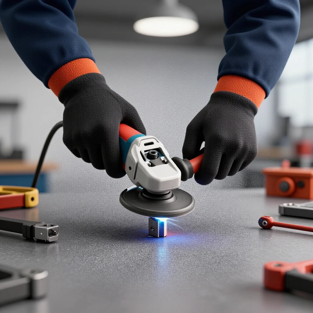
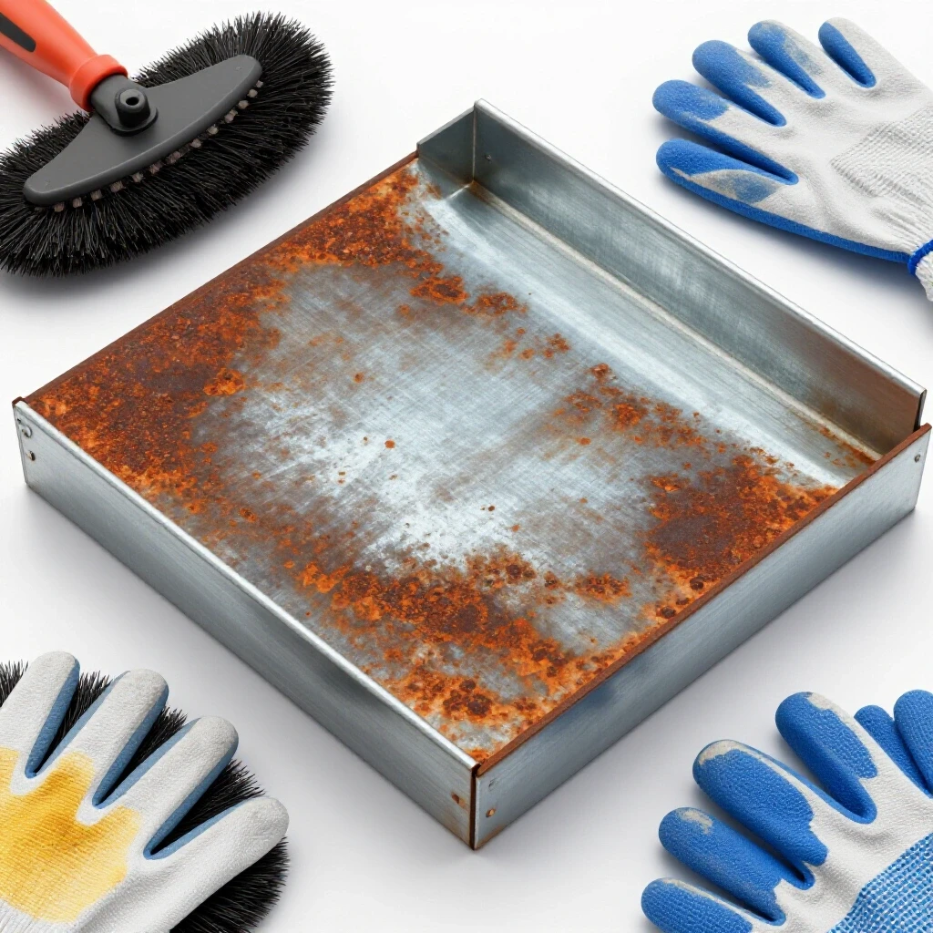
- Clean the Base Metal: Use a flap disc to remove all mill scale and rust within two inches of the joint.
- Verify Polarity: Ensure the torch is connected to the negative terminal (DCEN).
- Set Stick-Out: Maintain a consistent 3/4 inch distance from the tip to the work.
- Check Input Power: Ensure no other high-draw tools are on the same circuit.
- Test Bend: Perform a sacrificial weld and break it to verify penetration.
Conclusion
Mastering the use of budget equipment isn’t about the price tag; it’s about the depth of your diagnostic skills. By treating the welding process as a mechanical system—one that requires alignment, calibration, and variable control—you can achieve results that rival much more expensive setups. I have found that self-shielded flux-core is more than strong enough for 6mm steel, provided the operator understands how to isolate and fix the common points of failure.
The key is to stop guessing. If a weld looks bad, don’t just keep welding. Stop, look at the slag, check your wire feed tension, and verify your electrical input. Use the bend test to prove your work to yourself. When you move from “random guesswork” to “systematic troubleshooting,” you gain a level of confidence that no machine can give you. You become the specialist who knows exactly why a joint holds and, more importantly, how to fix it when it doesn’t.
FAQ: Troubleshooting Gasless Flux-Core Reliability
Can gasless flux-core welding really handle 6mm thick steel? Yes, it can. However, it requires a systematic approach to heat management. For 6mm material, you are usually at the upper limit of budget 120V machines. You must ensure you have a dedicated circuit and use a slow travel speed to allow the puddle to “wet out” and penetrate the root. If the bead looks like a rope sitting on top of the metal, you haven’t achieved a structural bond.
Why does my gasless weld have so many small holes (porosity)? This is usually a diagnostic issue involving your technique or environment. The most common cause is a “push” travel angle. You must “drag” the torch so the slag stays behind the puddle. Other causes include a stick-out that is too short (less than 1/2 inch) or moisture in the wire. Check your contact-to-work distance (CTWD) and ensure it stays around 3/4 of an inch.
Is budget flux-core wire as strong as the expensive stuff? In my testing, the difference isn’t in the raw tensile strength but in the “feedability.” Cheap wire is often poorly wound or has inconsistent diameters, leading to the “tool chatter” effect in your feeder. The chemical properties are usually sufficient for non-critical shop projects, but you must troubleshoot the mechanical feed issues to get a consistent, strong bead.
Why is my welder “stuttering” even though my settings are correct? This is likely a mechanical feed issue. Check your drive roll tension. If it’s too tight, you’re deforming the wire. If it’s too loose, it’s slipping. Also, check the liner inside the torch lead. If it’s clogged with dust or metal shavings, the wire won’t move smoothly, causing the arc to fluctuate and weakening the final joint.
How can I tell if my weld is strong without an X-ray? The “90-degree bend test” is the best shop-floor method. Weld a sample T-joint and try to break it by bending the vertical piece over the weld. A strong weld will either hold or tear the base metal. If the weld “unpeels” from the surface, you have a lack of fusion, which is a common failure point in budget setups.
What polarity should I use for gasless flux-core? Almost all self-shielded flux-core wires require DCEN (Direct Current Electrode Negative). This means the torch is negative and the ground clamp is positive. If you have this backward, the arc will be violent, create massive spatter, and result in a very shallow, weak weld. Always check your machine’s internal polarity jumpers.
Does wire diameter affect the strength of the joint? For 6mm steel, 0.035-inch wire is generally better than 0.030-inch. The thicker wire can carry more current, which helps with penetration. However, if your machine is low-powered, it might struggle to melt 0.035-inch wire consistently. In that case, 0.030-inch wire with a slower travel speed might actually produce a deeper, stronger weld.
How do I stop the slag from getting trapped inside the weld? This is known as slag inclusion. It happens when you don’t give the slag enough time to float to the top of the molten pool. To fix this, increase your voltage slightly or slow down your travel speed. Also, ensure your “drag” angle is about 15 to 20 degrees. If the angle is too steep, you can trap slag under the leading edge of the puddle.
Can I weld over old paint or rust with gasless flux-core? While flux-core is more “forgiving” than MIG, you should never weld over heavy rust or paint if you want a strong joint. Contaminants turn into gas in the weld pool, causing porosity and “brittleness.” For a diagnostic-grade repair, always grind the metal to a shiny finish. This ensures the best electrical contact and the cleanest metallurgical bond.
Why does my wire keep “bird-nesting” at the drive rolls? Bird-nesting is usually caused by a blockage in the liner or a contact tip that has “welded” itself to the wire. When the wire can’t move forward, the drive rolls keep pushing, and the wire tangles. To prevent this, always use a fresh contact tip and keep your torch lead as straight as possible to minimize friction.
(This article was written by one of our staff writers, Paul Whitaker. Visit our Meet the Team page to learn more about the author and their expertise.)