How to Build a Custom Motorized Pipe Welding Rotator (Plan)
I have spent the better part of two decades in fabrication shops, often under the flickering glow of overhead lights, trying to figure out why a machine isn’t doing what it was designed to do. There is a specific kind of frustration that sets in when a project you have built with your own hands starts to fail. You pull the trigger on the MIG gun, the pipe starts to turn, and suddenly, the weld pool stutters. Or worse, the pipe begins to “walk” off the rollers, threatening to drop hundreds of pounds of steel onto your feet.
In my 18 years as a millwright and diagnostic specialist, I have learned that these issues are rarely random. They are the result of measurable physical forces and mechanical tolerances. Whether you are dealing with a motor that hums but won’t turn or a weld that looks like Swiss cheese due to porosity, the solution lies in a systematic approach. We don’t guess in this shop; we isolate, test, and verify.
When you are constructing a motorized system to rotate workpieces for welding, you are essentially building a specialized lathe. The challenges you face—alignment, vibration, and electrical interference—are the same ones I’ve tackled in massive industrial mills. This guide is designed to help you navigate those hurdles using the same diagnostic frameworks I use every day.
Establishing a Baseline for Mechanical Precision
A mechanical baseline is the set of measurements and conditions where a machine is considered “square” and “true.” Without this baseline, you are building on a foundation of errors that will multiply as soon as the motor starts turning.
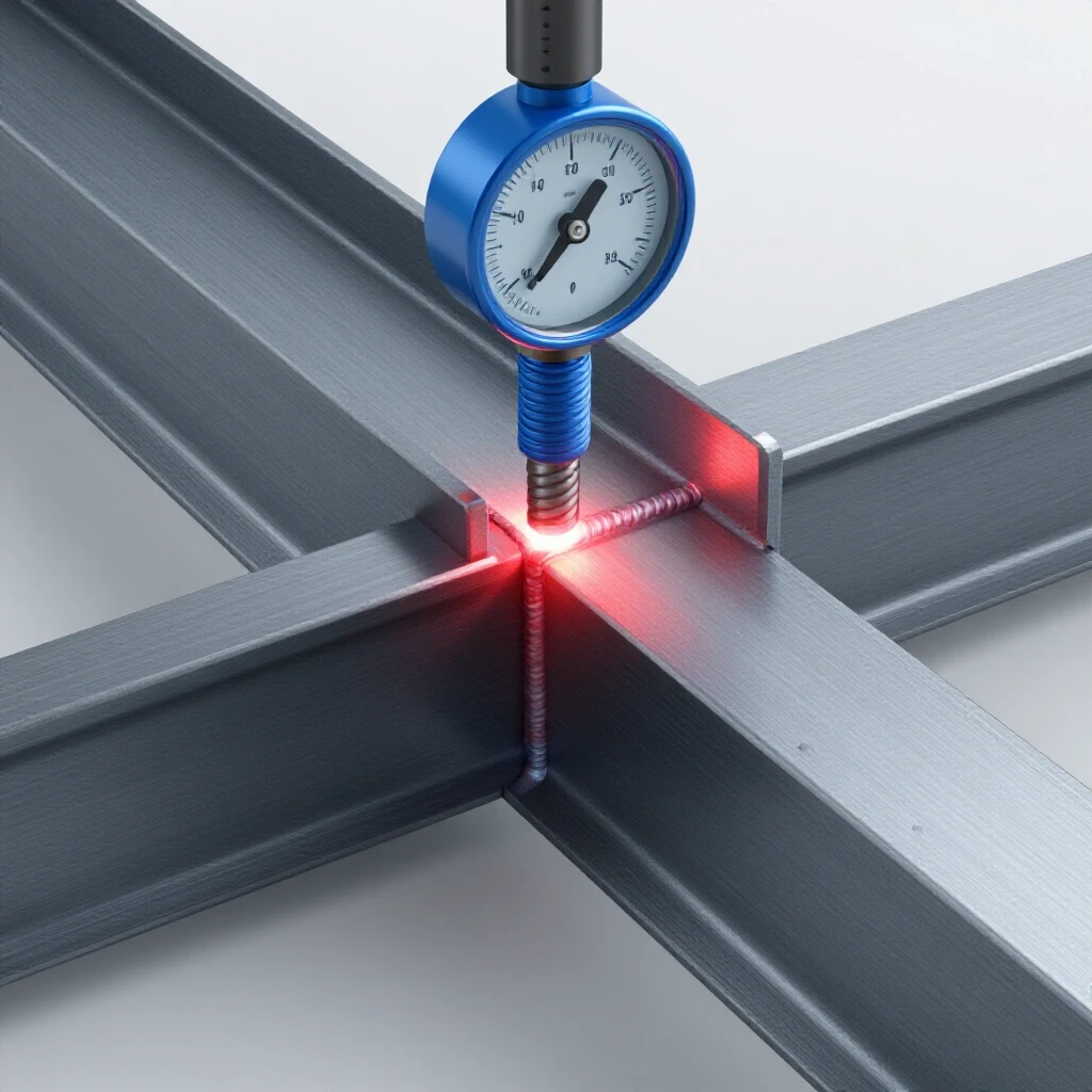
In a rotating weld fixture, the most critical baseline is the parallelism of the rollers. If the drive roller and the idler rollers are not perfectly parallel to each other and the floor, the workpiece will not stay centered. It will move axially, a phenomenon known as “walking.” I once spent three days on a job site because a crew couldn’t figure out why their pipe joints were gapping. It turned out the main frame was twisted by only 0.010 inches over four feet, but that was enough to pull the pipe out of alignment during every rotation.
Identifying and Correcting Axial Drift
Axial drift is the unintended horizontal movement of a cylindrical workpiece along its longitudinal axis during rotation. This is almost always caused by a lack of parallelism between the rollers or a frame that is out of square.
To diagnose this, I use a simple “string and square” method or a digital protractor. You want to ensure that the distance between the rollers is identical at both the front and the back of the frame. If you find a deviation of more than 0.03125 (1/32) of an inch, you will experience drift.
- Step 1: Measure the distance between the centers of the roller shafts at both ends.
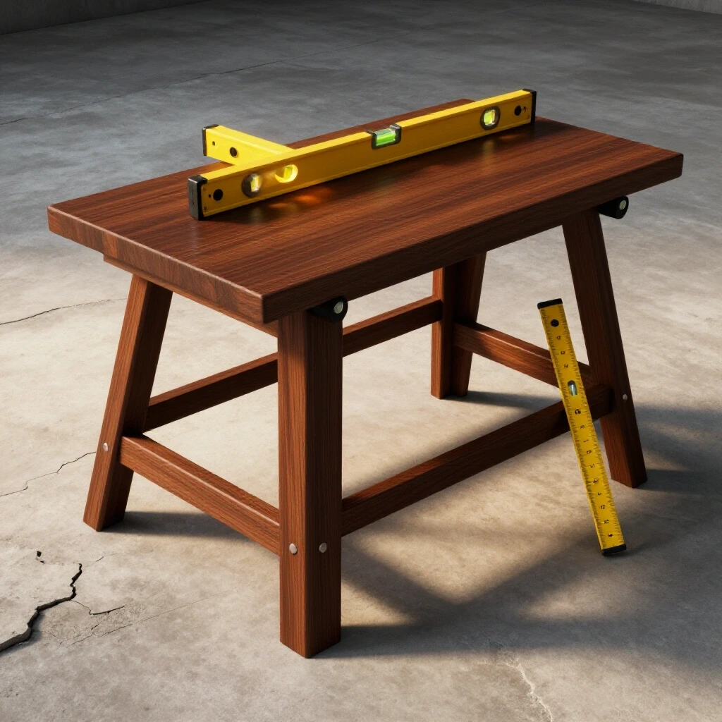
- Step 2: Check the frame for “wind” or twist by placing a precision level across the rollers.
- Step 3: Use shims under the bearing housings to bring the rollers into a parallel plane.
| Symptom | Probable Cause | Diagnostic Tool | Tolerance Limit |
|---|---|---|---|
| Pipe walks to the left | Right-side rollers are “toed-in” | Dial Indicator | < 0.005″ deviation |
| Intermittent “jumping” | Flat spot on roller or debris | Visual Inspection | No visible flat spots |
| Heavy vibration at speed | Shaft eccentricity | Digital Caliper | < 0.002″ runout |
Dampening Harmonics in Motorized Drive Systems
Vibration is the enemy of a clean weld. In a motorized rotation setup, vibrations often manifest as “chatter,” which creates ripples in the weld bead. This is usually caused by resonant harmonics—the frequency at which a mechanical system naturally vibrates.
When I was troubleshooting a custom-built positioner for a high-pressure gas line, the operator complained of “stuttering” in the motor. After hooking up a vibration spectrum analyzer on my smartphone, I realized the thin-walled tubing used for the frame was acting like a tuning fork. The motor’s RPM hit a specific frequency that matched the frame’s natural resonance, causing the whole assembly to shake.
Isolating Gearbox Backlash and Coupler Slop
Backlash is the amount of clearance between mating gear teeth or mechanical components. If your drive system has too much play, the pipe will not rotate smoothly; it will move in a series of tiny “starts and stops.”
To test for backlash, turn the power off and try to rotate the drive roller by hand. If you can move the roller more than a few degrees before the motor shaft resists, you have a backlash problem. This is common in cheap worm-gear reducers.
- Check the set screws: A loose set screw on a sprocket or coupler is the most common “hard to find” vibration source.
- Inspect the chain tension: If using a chain drive, ensure there is about 2% to 3% slack. Too tight, and you’ll ruin the bearings; too loose, and you’ll get “whip” vibrations.
- Verify coupler alignment: If the motor shaft and the roller shaft are joined by a coupler, they must be aligned within 0.005 inches to prevent “eccentric loading.”
Resolving Weld Defects in Automated Circumferential Joints
When you move from manual welding to a motorized rotation system, the physics of the weld pool changes. You are no longer moving the torch; the metal is moving under the arc. This shift can introduce specific defects, most notably porosity and inconsistent penetration.
Welding porosity is the presence of small gas pockets trapped in the weld metal. In a rotating setup, this is often caused by a “drag” in the rotation speed or a poor electrical ground. If the pipe stutters, the shielding gas coverage is interrupted for a fraction of a second, allowing atmospheric nitrogen and oxygen to contaminate the pool.
Troubleshooting Porosity and Shielding Gas Coverage
If you see bubbles or “pinholes” in your weld, you need to look at your gas flow and your rotation stability.
- Shielding Gas Flow: Aim for 20 to 30 Cubic Feet per Hour (CFH). Too much flow can actually cause turbulence, sucking air into the weld.
- The Grounding Path: This is where most builders fail. You cannot ground the frame and expect the current to travel through the bearings to the pipe. This will “arc out” your bearings, pitting the balls and races. You must use a dedicated rotary ground clamp or a spring-loaded brass brush that contacts the pipe directly.
- Surface Contamination: Rotating a pipe often flings hidden mill scale or oil into the path of the torch. Always clean at least two inches back from the joint with a dedicated stainless steel wire brush.
| Defect | Cause | Fix |
|---|---|---|
| Porosity | Shielding gas turbulence or poor ground | Check CFH; use rotary ground |
| Lack of Fusion | Rotation speed too high | Reduce RPM; check IPT (Inches Per Minute) |
| Undercut | Torch angle or high voltage | Adjust torch to 15-degree lead angle |
| “Cold Lap” | Rotation speed too slow | Increase RPM to keep arc on leading edge |
Electrical Diagnostics for Speed Stability
The heart of a motorized rotation fixture is the DC motor and its speed controller. If the speed fluctuates, the heat input of your weld fluctuates. This leads to uneven penetration.
I once worked on a project where the motor would slow down every time the welder started an arc. We spent hours checking the motor before realizing the welder and the motor controller were on the same 110V circuit. The “voltage drop” from the welder was starving the motor controller.
Testing the Controller and Motor Health
To troubleshoot electrical “gremlins,” you need a digital multimeter and a basic understanding of Ohm’s Law (Voltage = Current x Resistance).
- Check for Voltage Drop: Measure the voltage at the motor controller input while the welder is running. If it drops more than 5%, you need a dedicated circuit.
- Test the Potentiometer: The speed control knob (potentiometer) can develop “dead spots.” With the power off, measure the resistance (Ohms) as you turn the knob. It should increase or decrease smoothly. If the numbers jump wildly, the part is bad.
- Monitor Back-EMF: Back-Electromotive Force is the voltage a motor generates while it is spinning. If your motor controller doesn’t have “IR Compensation,” the motor will slow down when the weight of a heavy pipe is applied. Look for a controller that explicitly mentions “load compensation” or “constant torque.”
Case Study: The Case of the “Stuttering” Six-Inch Schedule 40
A colleague of mine built a setup using a 90V DC gear motor and a basic PWM (Pulse Width Modulation) controller. He was trying to weld 6-inch Schedule 40 pipe, but the weld bead looked like a series of grapes rather than a smooth stack of dimes.
We started by isolating the variables. First, we ran the motor without a load. It was smooth. Then, we added the pipe. The stuttering began. I used a dial indicator on the drive shaft and found 0.008 inches of runout. That doesn’t sound like much, but on a 6-inch pipe, that eccentricity caused the motor to “fight” the weight of the pipe on every rotation.
We replaced the cheap zinc-cast coupler with a machined steel spider coupler and added a 50-pound counterweight to the opposite side of the pipe to balance the heavy weld joint. The stuttering vanished. The lesson? Mechanical imbalance often looks like an electrical fault.
Actionable Tracking and Calibration Checklist
Before you start your next big fabrication project, use this checklist to ensure your equipment is calibrated.
- Roller Parallelism: Measure at four points; maximum deviation 0.015″.
- Bearing Lubrication: Use high-temp grease; check for “gritty” rotation.
- Grounding Integrity: Measure resistance between the pipe and the ground clamp; it should be less than 0.5 Ohms.
- Speed Calibration: Use a piece of tape on the pipe and a stopwatch. Calculate Inches Per Minute (IPM). For most MIG applications, 10-20 IPM is the sweet spot.
- Fastener Torque: Check every set screw and mounting bolt. Use blue thread-locker on anything that vibrates.
- Thermal Check: After 15 minutes of use, check the motor temperature with an infrared thermometer. If it’s over 150°F (65°C), you are overloading the motor or have a mechanical bind.
Mastering the Diagnostic Mindset
Troubleshooting is not about being the smartest person in the room; it’s about being the most disciplined. When your motorized rotation system fails, don’t start turning knobs and swapping parts. Stop. Observe. Measure.
Start with the mechanical frame. Is it square? Move to the drivetrain. Is there slop? Check the electrical. Is the voltage steady? Finally, look at the weld itself. What is the metal telling you? Porosity usually points to gas or ground; undercut points to speed or heat.
By following this systematic approach, you turn a frustrating breakdown into a simple engineering problem. You aren’t just fixing a machine; you are refining your process. That is the mark of a true fabricator.
Frequently Asked Questions
Why does my pipe keep moving sideways while it rotates?
This is called axial drift. It happens because your rollers are not perfectly parallel to each other. Even a tiny “toe-in” or “toe-out” acts like the steering on a car, pulling the pipe in one direction. Use a dial indicator or a precision square to ensure all roller shafts are perfectly parallel.
How do I stop my welding arc from ruining my motor bearings?
You must provide a path of least resistance for the electricity that does not involve the bearings. Standard ball bearings are not designed to carry welding current; the electricity will “arc” across the internal gaps, causing “fluting” or pitting. Use a dedicated rotary ground clamp that attaches directly to the workpiece.
What is the best motor speed for welding a 4-inch pipe?
Welding speed is measured in Inches Per Minute (IPM), not just RPM. For a standard MIG weld, you generally want to travel at 10 to 20 IPM. For a 4-inch pipe (which has a circumference of about 12.5 inches), you would want a rotation speed of roughly 0.8 to 1.6 RPM.
Why is my DC motor humming but not turning the pipe?
This usually indicates either a mechanical bind or a “stalled” motor. Check if the pipe weight exceeds the motor’s torque rating. Also, check the brushes on your DC motor; if they are worn down to the springs, the motor won’t have the “oomph” to start under load.
Can I use a standard light dimmer to control my motor speed?
No. A light dimmer is designed for resistive loads, not inductive loads like motors. Using one will likely burn out the motor or the dimmer itself. You need a dedicated PWM (Pulse Width Modulation) or SCR (Silicon Controlled Rectifier) controller designed for the specific voltage and amperage of your motor.
My weld has lots of tiny holes (porosity). Is the motor causing this?
Indirectly, yes. If the motor is stuttering, it disrupts the “arc time” and the shielding gas envelope. However, the most common cause in rotating fixtures is a poor ground or air currents in the shop being pulled into the weld pool by the rotation of the pipe.
How much “play” or backlash is acceptable in the gearbox?
For welding, you want as little as possible. If you have more than 0.005 inches of backlash, the pipe may “lurch” when the weld pool creates drag. If your gearbox has too much play, you can often “pre-load” the system by slightly offsetting the weight of the pipe or using a drag brake.
What kind of rollers are best for a DIY welding setup?
Polyurethane-coated rollers are excellent because they provide high friction (preventing slipping) and help dampen vibrations. However, they can melt if they get too close to the weld zone. For heavy-duty or high-heat applications, use machined steel rollers with a knurled surface for grip.
(This article was written by one of our staff writers, Paul Whitaker. Visit our Meet the Team page to learn more about the author and their expertise.)