How to Identify and Fix MIG Welding Porosity (DIY Tutorial)
I have spent the last 18 years in fabrication shops, and few things are as frustrating as a process that suddenly fails for no apparent reason. You are halfway through a critical frame build, your settings are dialed in, and suddenly, your weld beads look like a piece of Aero chocolate. This internal voiding, often called porosity, is the enemy of structural integrity and clean aesthetics.
In my experience as a diagnostic specialist, I have learned that “guessing” at a fix usually wastes more time than it saves. Whether I am hunting down a 0.002-inch misalignment in a lathe or trying to figure out why a MIG bead is bubbling, the approach is the same. We must isolate variables, test one change at a time, and rely on data rather than intuition.
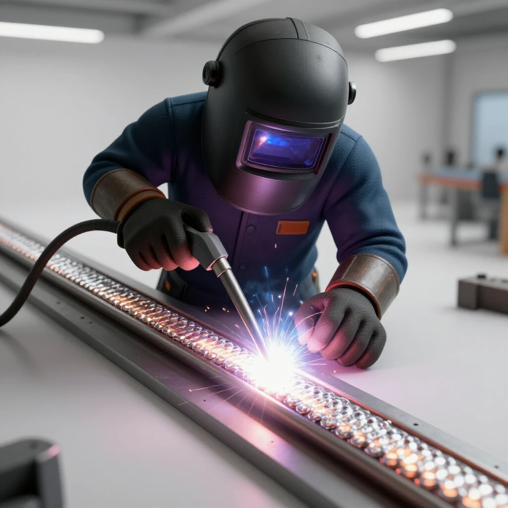
When gas becomes trapped in the molten weld pool as it solidifies, it leaves behind small holes or “pits.” These can be on the surface or buried deep within the metal. In this guide, we will walk through the systematic steps to find out why your gas shield is failing or why your base metal is reacting poorly, ensuring your repairs are permanent and your downtime is minimal.
Establishing a Systematic Diagnostic Framework for Weld Defects
A diagnostic framework is a structured method used to identify the root cause of a failure by isolating individual components of a system. By following a step-by-step path, you avoid the “shotgun approach” of changing five settings at once and never knowing which one actually solved the problem.
In the world of metal fabrication, we often deal with “ghost” issues—problems that appear and disappear without warning. To solve these, I use a three-stage process: Observation, Isolation, and Variable Control. Observation involves looking at the specific shape and location of the holes in your bead. Isolation means separating the gas delivery system from the electrical system. Variable Control is the final step where we adjust one setting at a time to confirm the fix.
When I was troubleshooting a large industrial feeder mill years ago, we had intermittent bubbling in the welds that occurred only in the afternoons. By using a systematic log, we discovered that a bay door was being opened at 2:00 PM every day, creating a cross-draft that blew away the shielding gas. Without a framework, we might have replaced the entire welding machine before noticing the open door.
Implementing the Isolate-and-Test Method
The Isolate-and-Test method involves breaking the welding system into four quadrants: the gas delivery path, the mechanical wire feed, the base material condition, and operator technique. By testing each quadrant independently, you can quickly rule out functional components and focus your energy on the actual fault.
- Gas Delivery: Check the tank, regulator, hose, and internal solenoid.
- Mechanical Feed: Inspect the liner, contact tip, and drive rolls for obstructions.
- Base Material: Analyze the cleanliness and chemical state of the steel.
- Operator Technique: Review the torch angle, travel speed, and distance from the work.
Evaluating Shielding Gas Flow and Delivery Consistency
Shielding gas flow refers to the volume of gas—typically a mix of Argon and CO2—that exits the nozzle to protect the molten puddle from atmospheric nitrogen and oxygen. Delivery consistency ensures that this flow remains steady and laminar, rather than turbulent or intermittent, throughout the duration of the weld.
If your gas flow is too low, the atmosphere will contaminate the weld. If it is too high, it can actually pull air into the puddle through a venturi effect, causing the very problem you are trying to prevent. I generally recommend a flow rate of 25 to 30 Cubic Feet per Hour (CFH) for most indoor shop environments.
| Component | Common Fault | Diagnostic Sign |
|---|---|---|
| Regulator | Diaphragm leak | Hissing sound or frosted body |
| Gas Hose | Internal kinking | Erratic flow at the nozzle |
| Solenoid | Stuck partially closed | Low flow despite high CFH setting |
| Nozzle | Spatter buildup | Turbulent gas flow and uneven beads |
| O-Rings | Cracked or dry | Sucking air into the gas stream |
Testing for Internal Gas Leaks and Obstructions
One of the most overlooked areas is the internal plumbing of the MIG gun. To test this, I use a simple “nozzle flow meter” that fits over the end of the torch. This tells you exactly what is coming out of the gun, rather than what the regulator says is leaving the tank. If the regulator reads 30 CFH but the nozzle meter reads 10 CFH, you have a leak or a blockage in the lead.
- Check the O-rings at the back of the power pin where it plugs into the machine.
- Inspect the gas diffuser holes; these small ports can become clogged with “fines” from the welding wire.
- Listen for a “click” from the solenoid when the trigger is pulled, which confirms electrical activation.
- Submerge the gas hose in a bucket of water (while disconnected from the machine) to look for bubbles indicating a puncture.
Identifying Surface Contamination and Material Prep Faults
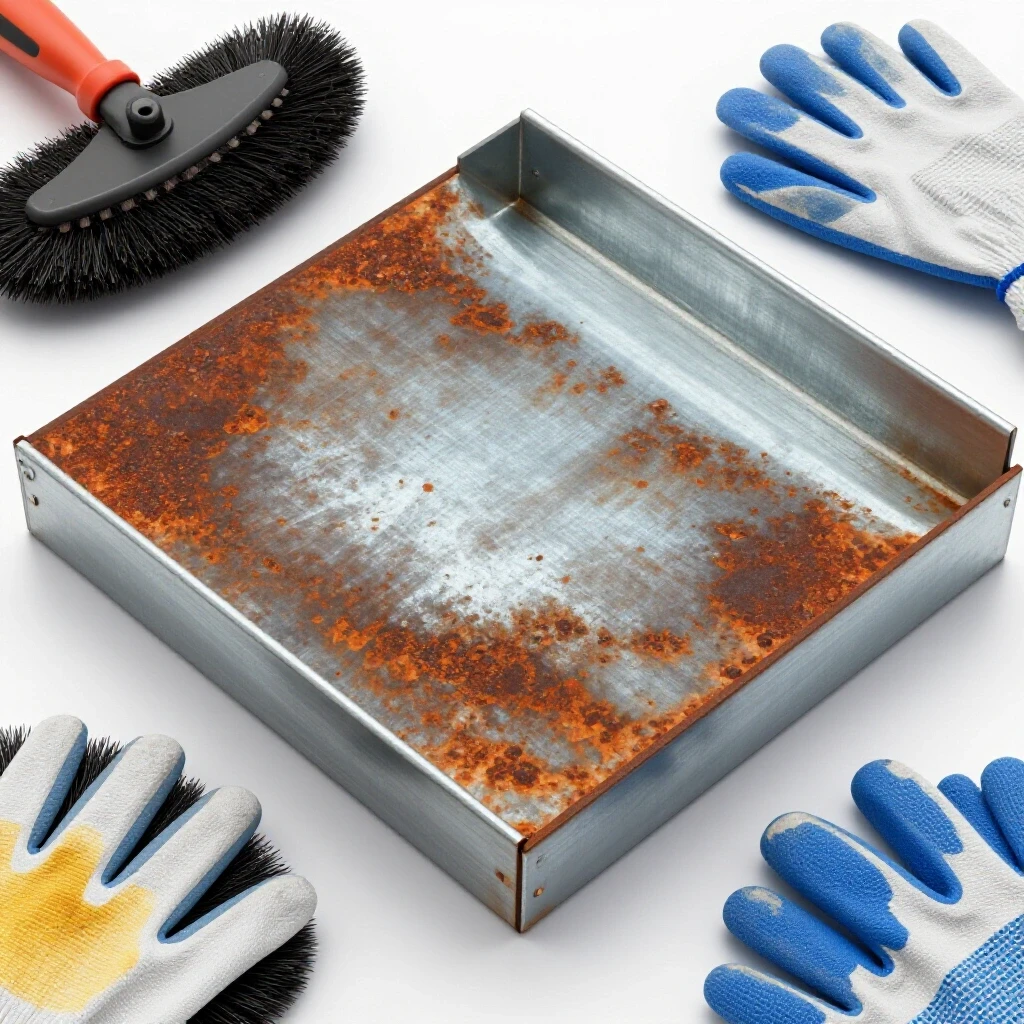
Surface contamination involves any foreign substance on the base metal—such as oil, rust, moisture, or mill scale—that reacts with the welding arc. Material prep is the mechanical process of removing these contaminants to ensure the molten metal bonds only with clean, solid steel.
I have seen many fabricators try to weld through “clean-looking” steel only to find massive internal voiding. The culprit is often hydrocarbons or moisture trapped in the microscopic pores of the metal. If you are working in a cold shop, for example, condensation can form on the steel as soon as the arc hits it, turning that water into hydrogen gas that gets trapped in the bead.
The Impact of Mill Scale and Chemical Residues
Mill scale is the flaky, blue-black layer of iron oxide found on hot-rolled steel. While it looks solid, it is actually a poor conductor and contains trapped oxygen. When the arc hits it, the scale breaks down and releases oxygen into the puddle, causing a chemical reaction that results in “wormholes” or surface pits.
- Mechanical Cleaning: Use a flap disc or a dedicated grinding wheel to reach bright, shiny metal.
- Chemical Cleaning: Use a residue-free cleaner like acetone to remove cutting oils or protective coatings.
- Thermal Prep: In humid environments, preheat the metal to 150-200 degrees Fahrenheit to drive off surface moisture.
- Backside Cleaning: Don’t forget to clean the back of the joint; contaminants can be sucked through the gap into the puddle.
Mechanical and Electrical Variable Isolation
Mechanical and electrical variables include the physical components that move the wire and the electrical circuit that maintains the arc. If the wire feed is jerky or the electrical contact is poor, the arc will fluctuate, leading to an unstable puddle that is more susceptible to atmospheric contamination.
I once spent three hours diagnosing a porosity issue on a CNC-controlled welding rig. We checked the gas three times. It turned out to be a worn-out contact tip. The hole in the tip had become oblong, causing the wire to “dance” inside it. This created a micro-arcing effect that disrupted the gas shield and introduced turbulence into the puddle.
Inspecting the Wire Feed Path and Contact Stability
The contact tip is the final point of electrical transfer to the wire. If this connection is loose or dirty, the voltage at the arc will drop, changing the way the metal transfers. This can lead to excessive spatter, which then clogs the gas nozzle and blocks your shielding gas.
- Replace the Contact Tip: If you see any signs of wear or “keyholing,” toss it. They are cheap insurance.
- Check Wire Tension: Too much tension can flake the wire coating, which then clogs the liner and causes erratic feeding.
- Inspect the Liner: Blow out the liner with compressed air every time you change a roll of wire to remove dust and metal shavings.
- Verify Ground Clamp: A weak ground causes “arc blow,” where the arc wanders and pulls in outside air. Ensure the ground is on clean, bare metal.
Correcting Operator Technique and Environmental Factors
Operator technique refers to the physical way the welder holds the torch and moves along the joint. Environmental factors are external conditions, such as wind or humidity, that can physically move the shielding gas away from the weld zone before it can do its job.
Even with a perfect machine, poor technique can cause a failure. The most common error I see is an excessive “stick-out,” technically known as Contact Tip to Work Distance (CTWD). If you hold the torch too far away, the gas disperses before it reaches the puddle. For most MIG applications, you want to maintain a distance of 3/8 to 1/2 of an inch.
Optimizing Torch Angle and Travel Speed
The angle at which you hold the torch determines how the gas is “pushed” or “pulled” over the weld. A 10 to 15-degree push angle is generally preferred for MIG welding on flat surfaces because it pre-cleans the path and keeps the gas focused over the leading edge of the puddle.
- Avoid Excessive Drag: A steep drag angle can “vacuum” air into the back of the puddle.
- Monitor Travel Speed: Moving too fast doesn’t give the gas enough time to shield the cooling metal.
- Block the Breeze: If you are working near a fan or an open window, set up welding screens. Even a 5 MPH breeze can strip away your gas shield.
- Nozzle Dip: Use anti-spatter spray or dip to prevent “grapes” from building up inside the nozzle, which creates gas turbulence.
Case Study: The Mystery of the Intermittent Pits
I remember a project involving a series of structural brackets for a custom mezzanine. The first ten welds were perfect, but the eleventh looked like a sponge. My first instinct was to check the gas tank, but it was half full. I checked the regulator, and it was steady at 25 CFH.
I decided to look closer at the wire. I noticed that as the spool unrolled, there were small patches of light corrosion on the wire itself. The spool had been sitting in a damp corner of the shop, and the moisture had seeped into the outer layers. Every time a rusty section of wire hit the arc, it released oxygen and caused instant porosity. We swapped the spool, stored the new one in a dry cabinet, and the problem vanished.
This taught me that “cleanliness” applies to the consumables just as much as the base metal. Always inspect your wire for rust, dust, or oily residues before starting a critical job.
Diagnostic Math: Calculating Gas Coverage and Wire Feed Speed
In precision fabrication, we don’t just “turn the knob until it feels right.” We use specific metrics to ensure the machine is operating within its designed tolerances. For MIG welding, the relationship between wire feed speed (WFS) and voltage is critical for a stable arc.
Wire Feed Speed Calculation: If you don’t have a digital readout, you can calculate your WFS manually. Pull the trigger for 6 seconds, measure the length of the wire that came out in inches, and multiply by 10. This gives you your Inches Per Minute (IPM).
Gas Coverage Metric: * Standard Nozzle (1/2″): 20-25 CFH * Large Nozzle (5/8″): 25-35 CFH * Spot Welding: 35-40 CFH (requires higher pressure to displace air in tight gaps)
Voltage Drop Tolerance: Using a multimeter, you should see no more than a 0.5V drop between the machine’s output terminal and the contact tip while welding. A larger drop indicates a failing lead or a loose internal connection.
Actionable Troubleshooting Checklist
Use this checklist when you encounter unexpected bubbling or holes in your weld beads. Follow the steps in order to isolate the cause systematically.
- Verify Gas Supply: Is the tank empty? Is the flow meter set to 25-30 CFH?
- Check for Drafts: Are there fans, open doors, or AC vents blowing on the work area?
- Inspect the Nozzle: Is it clogged with spatter? Is the gas diffuser tight?
- Examine the Base Metal: Is it ground to bright metal? Is there oil or moisture on the surface?
- Test the Lead: Are there kinks in the hose? Are the O-rings at the power pin intact?
- Evaluate Technique: Is your stick-out more than 1/2 inch? Is your torch angle too steep?
- Check Consumables: Is the wire rusty? Is the contact tip worn out?
Advanced Diagnostic Tools for the Modern Shop
While a good eye is essential, modern tools can help you find “invisible” problems much faster. I recommend keeping a few diagnostic items in your toolbox for when the standard checks fail.
- Digital Nozzle Flow Meter: This allows you to verify the actual gas flow at the torch head, bypassing any leaks in the machine or lead.
- Infrared Thermometer: Use this to check for “hot spots” on your electrical connections. A hot ground clamp or power pin indicates high resistance and a failing circuit.
- Magnifying Loupe (10x): Sometimes porosity is so small it looks like a rough surface. A loupe helps you see if those are actually tiny gas pockets.
- Smartphone Slow-Motion Video: Recording your arc at 240 frames per second can reveal “arc fluttering” or erratic wire feeding that is invisible to the naked eye.
Conclusion
Mastering the art of troubleshooting is about moving from frustration to calculation. When your welds start showing signs of gas entrapment, don’t start turning knobs at random. Stop, look at the evidence, and isolate the variables. Whether it is a $2 O-ring, a gust of wind from a shop fan, or a patch of mill scale you missed, the answer is always there if you follow the process.
By maintaining your equipment, keeping your materials clean, and practicing disciplined technique, you can eliminate 95% of common weld defects. For the remaining 5%, you now have the diagnostic framework to hunt them down and fix them for good.
Frequently Asked Questions
Why does my weld look fine at the start but get bubbly at the end?
This is often caused by heat buildup or gas coverage issues. As the nozzle gets hot, any internal contaminants or “nozzle dip” residue can vaporize and enter the gas stream. Additionally, if you are welding toward the edge of a plate, the shielding gas can “roll off” the edge, leaving the end of the weld unprotected.
Can I just weld over a porous spot to fix it?
No. Welding over porosity just traps the gas deeper in the metal or creates a larger void. The only correct fix is to grind out the defective area completely until you reach solid metal, then re-weld the joint.
How do I know if my gas solenoid is failing?
If you hear the “click” but get no gas, the solenoid may be stuck. If you get gas but it won’t stop flowing when you release the trigger, the solenoid is likely held open by debris. You can test the solenoid’s resistance with a multimeter; most should read between 30 and 100 Ohms.
Does the type of shielding gas affect porosity?
Yes. Pure CO2 is more prone to turbulence and spatter than an Argon/CO2 mix (like C25). While CO2 provides deeper penetration, the smoother arc of a mixed gas generally makes it easier to maintain a stable, gas-shielded puddle.
Is it possible for the wire itself to cause gas pockets?
Absolutely. If the wire is stored in a humid environment, it can develop microscopic surface oxidation. This rust contains oxygen and hydrogen, which are released directly into the molten puddle during the welding process.
What is the difference between surface porosity and “wormholes”?
Surface porosity appears as small pits on the face of the bead. “Wormholes” are long, tunnel-like voids that usually indicate a severe lack of shielding gas or a heavy reaction with contaminants like zinc (from galvanized steel) or thick mill scale.
How does torch angle specifically impact gas coverage?
Think of the gas nozzle like a flashlight. If you point it straight down, the “light” (gas) is concentrated. If you tilt it too far, the “light” spreads out and becomes dim. An angle greater than 20 degrees starts to pull outside air into the stream.
Can a worn-out liner cause gas issues?
While the liner carries the wire, a clogged liner causes “stuttering.” This stuttering interrupts the arc, which in turn causes the puddle to cool and solidify unevenly, often trapping gas that would otherwise have escaped.
Does wire diameter play a role in this?
Thinner wires (like .030) require less voltage and create a smaller puddle, which can freeze faster. This fast freezing gives gas bubbles less time to float to the surface, making technique and gas flow even more critical.
Why is my gas flow surging when I first pull the trigger?
This is usually caused by gas building up in the hose while the machine is idle. A high-quality regulator with a “surge-reduction” feature can help, or you can simply trigger the torch for a second away from the work to bleed off the pressure before starting your bead.
(This article was written by one of our staff writers, Paul Whitaker. Visit our Meet the Team page to learn more about the author and their expertise.)