Designing an Efficient Small Garage Workshop Layout (Plan)
For more than two decades, I have lived the evolution of the home-based workshop. I started with a single welder and a manual bender in a cramped corner, much like many of you. Over time, that space transformed into a high-output environment where CNC plasma tables and precision machining are the standard. The transition from a hobbyist setup to a semi-professional operation is rarely about buying more tools; it is about how those tools interact with your floor space.
The stress of scaling a fabrication business often comes from the friction of your surroundings. You might find yourself tripping over material or waiting for a single-phase circuit to cool down. I remember a specific project where I spent more time moving sheet metal than actually cutting it. That was the moment I realized that my shop was no longer a workspace; it was a bottleneck. To move forward, I had to stop thinking like a builder and start thinking like a manufacturing engineer.
Mapping the Physics of Production Flow
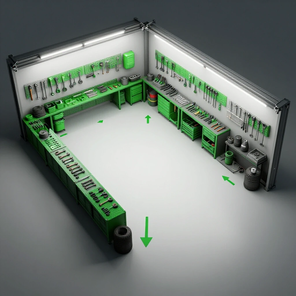
Production flow mapping is the practice of visualizing how raw materials enter your shop, move through various stages of fabrication, and exit as finished products. By identifying the physical path of a project, you can eliminate unnecessary movement that wastes time and energy.
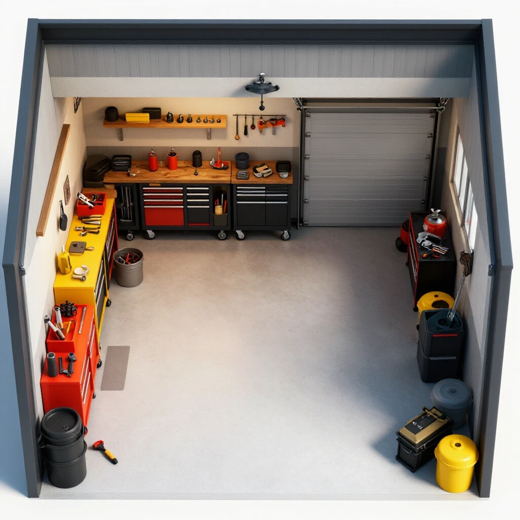
When you analyze an advanced workshop layout, you must look at the “spaghetti diagram” of your daily steps. In my early years, I realized I was walking across the garage four times just to prep a single bracket. A linear flow—where material moves from storage to cutting, then to welding, and finally to finishing—reduces this fatigue. If your CNC table is in the back corner but your raw steel is by the door, you are fighting the physics of your space every day.
- Raw Material Entry: Keep your heavy stock near the largest door to minimize manual lifting.
- Processing Zones: Group tools by their function, such as a “hot zone” for welding and a “clean zone” for electronics or assembly.
- Buffer Space: Leave room between stations for “work in progress” (WIP) so parts don’t pile up on your machine beds.
- The 3-Foot Rule: Maintain at least 36 inches of clearance around stationary power tools to ensure safe operation and maintenance access.
The Impact of Material Travel Paths on Throughput
A material travel path is the specific route a piece of work takes from start to finish. Minimizing this distance is the fastest way to increase the number of parts you can produce in a single shift.
In a small garage, every foot of movement counts. I once tracked my steps during a production run of twenty gate hinges. By moving my drill press three feet closer to the welding bench, I saved nearly a mile of walking over a month of work. This isn’t just about laziness; it is about reducing the physical toll on your body and keeping your mind focused on the craft rather than the commute across the floor.
| Layout Strategy | Primary Benefit | Typical Drawback |
|---|---|---|
| Process-Based Zoning | Efficient for varied, custom jobs | High material handling time |
| Product-Cell Layout | Extremely fast for repetitive parts | Inflexible if product design changes |
| Perimeter Loading | Maximum open floor space | Constant walking to center-room tools |
| Linear Flow | Predictable, logical movement | Requires a long, narrow workspace |
Structural Foundations and Floor Load Management
Floor load management involves calculating the weight-bearing capacity of your concrete slab to ensure it can support heavy machinery without cracking or shifting. This is critical when adding heavy equipment like a CNC plasma table or a large ironworker.
Most residential garage slabs are four inches thick, rated for roughly 3,000 to 4,000 PSI. While this is fine for a car, a heavy machine puts a “point load” on a very small area. When I installed my first 4×8 CNC table, I had to account for the weight of the water bed, the steel frame, and the gantry. If the floor settles even a fraction of an inch, your machine loses its level, and your precision disappears.
- Static Loads: The weight of the machine at rest.
- Dynamic Loads: The vibration and movement generated when the machine is running.
- Leveling Feet: Use heavy-duty adjustable mounts to distribute weight and compensate for floor slope.
- Anchor Bolts: Ensure you aren’t drilling too close to expansion joints, which can weaken the slab.
Engineering a 3-Phase Power Solution
A 3-phase power system provides three alternating currents that are out of phase with each other, allowing for more efficient and powerful motor operation. Most residential garages only have single-phase power, which limits the type of industrial machinery you can run.
When you scale up, you will eventually find a piece of equipment that requires 3-phase power. You have two main choices: a Rotary Phase Converter (RPC) or a Variable Frequency Drive (VFD). I prefer RPCs for shops with multiple machines because they act like a bridge, providing true 3-phase power to your entire sub-panel. VFDs are excellent for controlling the speed of a single motor, such as on a milling machine or a lathe, but they require individual installation for every tool.
- Rotary Phase Converter (RPC): A large idler motor that generates the third leg of power.
- Variable Frequency Drive (VFD): An electronic controller that changes the frequency of the power to control motor speed.
- Phase Balancing: Measuring the voltage between all three legs to ensure they are within 5% of each other.
- Sub-Panel Logic: Running a dedicated 3-phase panel makes it easier to add tools as your shop grows.
Comparing Power Conversion Methods
Choosing the right power delivery system depends on your specific tool list and how often you plan to run multiple machines at once.
| Feature | Rotary Phase Converter (RPC) | Variable Frequency Drive (VFD) | Static Phase Converter |
|---|---|---|---|
| Power Quality | High (True 3-phase) | High (Clean output) | Low (Reduced torque) |
| Multiple Tool Use | Yes, via a panel | No, usually 1:1 ratio | No |
| Speed Control | No | Yes | No |
| Installation | Complex wiring | Simple to moderate | Very simple |
Designing High-Volume Air Filtration and Fume Extraction
Air filtration and fume extraction systems remove hazardous particles and gases from the air to protect your health and keep the shop clean. In a small space, dust and smoke accumulate rapidly, making high-volume management a necessity.
I learned the hard way that a standard shop vac is not an air filtration system. When I integrated a CNC plasma table, the fine dust covered every surface in my garage within an hour. You need to calculate the Cubic Feet per Minute (CFM) required for your tools. A good rule of thumb is to aim for at least 1,000 CFM for a general fabrication area, with dedicated extraction at the source for welding and cutting.
- Source Capture: Extracting fumes at the point of origin, such as a smoke arm over a welding bench.
- Ambient Filtration: Using overhead “air scrubbers” to clean the air that escapes source capture.
- Static Pressure: The resistance air faces as it moves through ducts; larger pipes and fewer bends reduce this loss.
- Micron Ratings: Ensure your filters are rated for at least 1 micron to catch the finest, most dangerous dust.
Airflow Metrics for Common Fabrication Tools
Effective dust collection duct design requires matching the blower’s capacity to the specific needs of your machinery.
| Tool Type | Required CFM | Ideal Duct Diameter | Static Pressure Risk |
|---|---|---|---|
| CNC Plasma Table | 1,200 – 1,500 | 6 – 8 inches | High (Fine particulate) |
| Grinding Station | 500 – 800 | 4 – 5 inches | Moderate (Heavy sparks) |
| Sanding/Finishing | 400 – 600 | 4 inches | Low (Fine dust) |
| Welding Bench | 600 – 900 | 6 inches | Low (Fume focus) |
Integrating CNC Machinery into a Compact Space
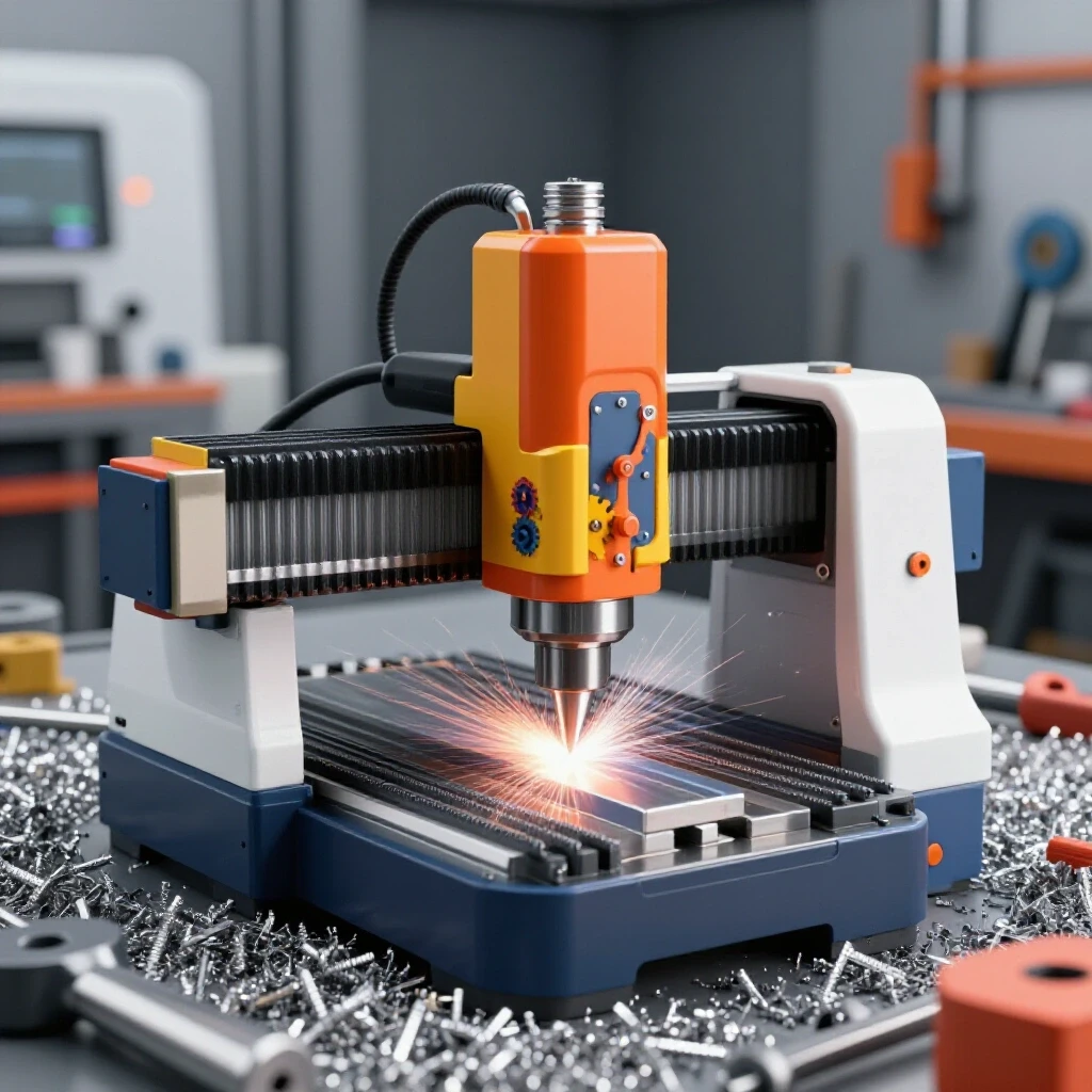
CNC (Computer Numerical Control) integration is the process of adding automated machinery into your workflow to increase precision and repeatability. This requires balancing the machine’s physical footprint with the digital infrastructure needed to run it.
Adding a CNC table to a garage is a game-changer, but it demands a different mindset. You are no longer just a fabricator; you are now a machine operator and a programmer. The biggest mistake I see is placing the CNC table in a way that blocks access to other tools. You need a dedicated “clean station” for your computer and controller, away from the sparks and metal dust.
- Gantry Clearance: Ensure the moving parts of the machine don’t hit walls or storage racks at their full range of motion.
- Cable Management: Use “drag chains” or overhead drops to keep power and signal cables off the floor.
- Grounding: CNC systems are sensitive to electrical noise; use a dedicated ground rod to prevent “ghost” signals.
- Water Bed Maintenance: If using a plasma table, plan for how you will drain and clean the water tray.
Software and CAD/CAM Workflow Synchronization
Workflow synchronization involves connecting your design software (CAD) with your manufacturing software (CAM) to create a seamless path from an idea to a finished part. This digital “bridge” is where most beginners struggle.
I spent months fighting with software that wouldn’t talk to my machine. The key is to standardize your file types. Most fabrication shops rely on DXF or SVG files for 2D work. By creating a library of “tooling files” with pre-set speeds and feeds for different metal thicknesses, you can reduce your setup time from twenty minutes to two minutes. This is the essence of lean manufacturing in a small shop.
- CAD (Computer-Aided Design): Use this to draw your parts with exact dimensions.
- CAM (Computer-Aided Manufacturing): This software turns your drawing into “G-code” that the machine understands.
- Post-Processor: A specific file that “translates” the G-code for your specific machine controller.
- Nesting Software: This optimizes how parts are laid out on a sheet of metal to minimize waste.
Actionable Benchmarks for Shop Optimization
To track your progress, you need measurable goals. These benchmarks help you determine if your layout changes are actually improving your efficiency or just moving the clutter around.
- Setup Time: Aim to reduce the time from “idea” to “first cut” by at least 30% through better software organization.
- Material Handling: If you have to move more than two items to reach your raw stock, your layout needs adjustment.
- Power Stability: Check your 3-phase balance every six months to ensure your converter is performing correctly.
- Filter Life: Monitor the pressure gauge on your dust collector; a 20% drop in airflow usually means it’s time for a cleaning.
Conclusion
Transitioning your garage into a high-efficiency fabrication space is a marathon, not a sprint. It requires a disciplined approach to how you use every square inch of floor and every amp of power. By focusing on linear material flow, upgrading to 3-phase power where necessary, and mastering the digital side of CNC integration, you move beyond the limits of a hobbyist.
Your next step should be a simple one: take a roll of masking tape and mark out the “dead zones” on your floor where material currently piles up. Once you see those bottlenecks clearly, you can begin the process of redesigning your space for the throughput you deserve. Efficiency isn’t about working harder; it’s about building a shop that works with you.
Frequently Asked Questions
How do I know if my garage floor can support a heavy CNC table?
Most standard residential garage floors are 4 inches of reinforced concrete. This is generally sufficient for tables up to 4,000 lbs, provided the weight is distributed across several leveling feet. If you are installing an industrial-grade milling machine or a table with a massive water bed, you should consult a local structural engineer to check for slab thickness and reinforcement.
Is a Rotary Phase Converter better than a VFD for a small shop?
It depends on your goals. A Rotary Phase Converter (RPC) is better if you want to power multiple 3-phase machines from one source. It provides a more traditional 3-phase power experience. A VFD is better for single machines where you need variable speed control, such as a lathe or a drill press. VFDs are often cheaper for a single tool but become expensive if you need one for every machine in the shop.
What is the most common mistake in duct design for dust collection?
The most common error is using too many 90-degree elbows and small-diameter pipes. Each bend and each inch of diameter reduction increases “static pressure loss,” which kills your suction. Use 45-degree bends where possible and keep your main trunk lines as large as your blower allows (usually 6 inches for a 2HP-3HP system).
How much space should I leave around my CNC plasma table?
You should maintain at least 3 feet of clearance on all sides where you need to load material or perform maintenance. If your table is against a wall, ensure the gantry has enough room to move without hitting the structure. Remember to leave space for the control console and the plasma power supply unit.
Do I really need a dedicated ground rod for my CNC equipment?
Yes. CNC electronics are highly sensitive to “EMI” (Electromagnetic Interference) generated by plasma cutters and welders. A dedicated ground rod, separate from your house’s electrical ground, helps drain this interference and prevents the machine from losing its position or crashing mid-cut.
What is the ideal CFM for a garage-based welding station?
For a standard welding bench, you should aim for 600 to 900 CFM at the source. This ensures that the fumes are pulled away from your face before they can disperse into the rest of the shop. If you are doing high-volume production welding, you may need a system rated for 1,200 CFM or more.
How can I reduce the noise of a Rotary Phase Converter?
RPCs can be loud because they are essentially a large motor running constantly. You can reduce the noise by mounting the converter on vibration-damping pads or placing it in a ventilated, sound-insulated enclosure. Never completely seal the enclosure, as the motor needs airflow to stay cool.
What file format is best for transitioning from CAD to CNC?
The DXF (Drawing Exchange Format) is the industry standard for 2D fabrication. It is recognized by almost every CAM software and CNC controller. For more complex 3D work, STEP files are the most reliable. Always ensure your CAD drawings are “cleaned” of overlapping lines before exporting to avoid errors in the CAM stage.
How often should I check the voltage balance on my 3-phase system?
You should check it during the initial setup and then every six months. If the voltage between any two legs varies by more than 5%, it can cause your motors to overheat or lose torque. This is especially important as you add more machines to the circuit.
Can I run a CNC table on a standard 20-amp circuit?
Most small-to-medium CNC tables require a dedicated 20-amp circuit for the controller and drive motors, plus a separate, higher-amperage circuit (often 50 amps) for the plasma cutter or spindle. Running both on the same circuit often leads to tripped breakers and electrical noise issues.
(This article was written by one of our staff writers, Edward Sinclair. Visit our Meet the Team page to learn more about the author and their expertise.)