How to Build a Leak-Free Welded Parts Washer Basin (DIY Plan)
There is a specific kind of frustration that sets in when you finish a long bead, lift your hood, and realize your workpiece has turned into a potato chip. Early in my career as a prototype technician, I was tasked with building a large fluid containment tray. I measured everything to the sixteenth of an inch, but I didn’t account for the massive physical force of cooling metal. By the time I finished the final corner, the bottom of the tray had bowed up two inches, and the sides looked like a swinging gate. It was a humbling lesson in how heat moves steel.
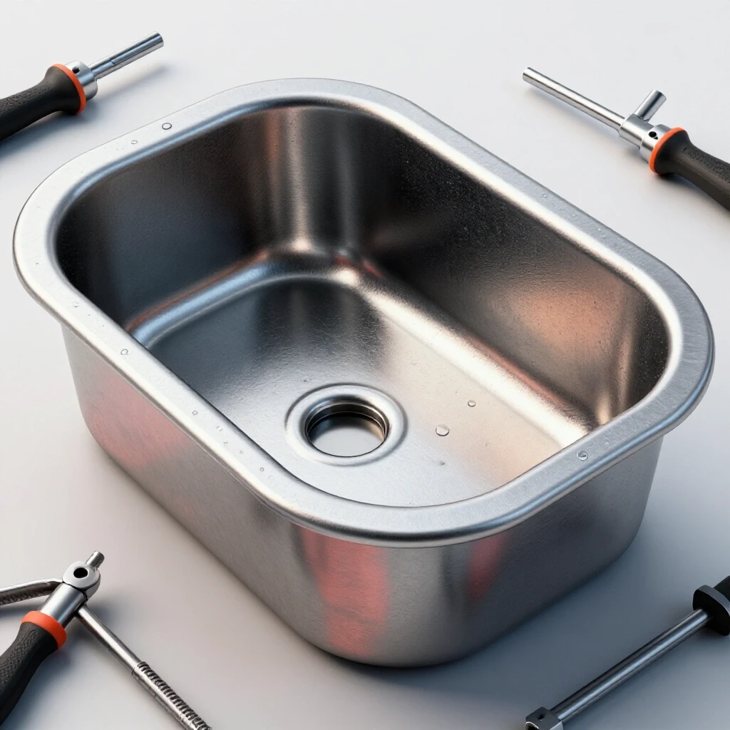
Building a watertight metal container requires more than just a steady hand with a MIG gun. It demands a strategy for managing thermal expansion and contraction. When you are fabricating a shop basin meant to hold liquids, the stakes are higher than a simple workbench. A single pinhole or a warped flange means a messy floor and a wasted weekend. I’ve learned that success happens in the prep work—the way you cut your sheet, the order of your tacks, and the patience you show during the final welding passes.
Selecting Materials for Durable Workshop Basins
Choosing the right metal involves balancing weight, weldability, and structural rigidity to ensure the finished container remains stable under the weight of heavy parts.
For a standard utility basin, I almost always reach for 14-gauge or 16-gauge mild steel sheet. 16-gauge is roughly 0.060 inches thick, making it easy to form but prone to warping if you get too aggressive with the heat. 14-gauge, at about 0.075 inches, offers a bit more “meat” for the weld and resists oil-canning (that popping sound metal makes when it bows). If you go much thinner, like 18-gauge, you’ll find yourself blowing through the metal. If you go thicker, the basin becomes unnecessarily heavy and difficult to move around the shop.
Mild steel is the preferred choice for most DIYers because it is forgiving. It has a predictable expansion rate and is easy to clean before welding. When sourcing your metal, look for “pickled and oiled” (P&O) sheet if possible. It lacks the heavy mill scale found on hot-rolled steel, which saves you hours of grinding. If you have to use hot-rolled, you must grind every edge back to shiny metal at least half an inch from the joint. Any scale left behind will contaminate the weld, leading to porosity and inevitable leaks.
Layout Principles and Kerf Calculation
Accurate layout is the foundation of a square project, requiring you to account for the thickness of the cutting tool to ensure the final pieces fit together without gaps.
When I plan my cuts, I always start with a detailed cut list. One mistake I see often is forgetting the “kerf”—the width of the material removed by the saw blade or plasma torch. If you are using a standard abrasive chop saw, that kerf can be 1/8 of an inch. If you make four cuts without accounting for it, your final piece could be half an inch short. For a basin that needs to be watertight, a tight fit-up is mandatory. Gaps are the enemy of a leak-free seal because they require more heat and filler metal to bridge, which increases the risk of warping.
I prefer to use a cold saw or a metal-cutting circular saw for long straight cuts. These tools leave a clean edge and have a much thinner kerf, usually around 1/16 to 3/32 of an inch. After cutting, I use a squaring square to check every corner. If your base plate isn’t perfectly square, your side walls will never align. I aim for a dimensional tolerance of +/- 1/16th of an inch across the entire layout.
| Cutting Method | Average Kerf Width | Edge Quality | Heat Input |
|---|---|---|---|
| Plasma Cutter | 0.040″ – 0.060″ | Moderate (requires cleanup) | High |
| Abrasive Saw | 0.125″ | Rough (burrs) | Moderate |
| Cold Saw | 0.060″ – 0.090″ | Excellent (machined finish) | Low |
| Oxy-Fuel Torch | 0.125″ – 0.150″ | Rough (heavy slag) | Very High |
Preparing Joints for Watertight Integrity
Joint preparation is the process of cleaning and shaping the edges of the metal to ensure maximum weld penetration and a contaminant-free fusion zone.
To get a leak-free seal, you need to think about the “fit-up.” For 14-gauge steel, an outside corner joint is often the best choice for the vertical seams of a basin. This allows you to weld into the “V” created by the two meeting edges. Before the pieces ever touch, I use a flap disc (60 or 80 grit) to bright-clean the edges. Even a tiny amount of rust or oil will cause the weld puddle to “spit,” creating microscopic holes that you might not see until the basin is full of fluid.
I also recommend a slight bevel on the edges if you are using material thicker than 1/8 inch, though for 14-gauge, it isn’t strictly necessary. The goal is to ensure the weld bead penetrates through the entire thickness of the metal. If you only weld the surface, the joint can crack under the weight of the liquid or during a temperature swing. A good rule of thumb is that if you can see a consistent “heat tint” on the inside of the basin after welding the outside, you’ve achieved decent penetration.
Building Workshop Jigs and Fixtures
Fixtures are temporary structures or clamps used to hold metal components in the correct orientation during the welding process to prevent movement.
You cannot hold a basin square by hand. Metal moves with a force that will laugh at your grip strength. I use a dedicated fabrication table, but if you don’t have one, a flat concrete floor or a heavy wooden workbench topped with a thick steel plate will work. The key is to use “stops” or “dogs” to lock your base plate in place. I often weld small scraps of angle iron to my table to act as a temporary jig. These scraps hold the side walls at a perfect 90-degree angle while I set my tacks.
Clamping is equally important. I place clamps every 6 to 8 inches along the seam. This prevents the metal from “bowing” out in the middle of a long run. If you are building a rectangular basin, measuring the diagonals is the fastest way to check for square. If the measurement from the front-left corner to the back-right corner matches the other diagonal, you are square. Even a 1/8-inch difference will make the basin look “racked” and can cause the bottom to wobble.
Strategic Tacking for Structural Stability
Tack welding involves placing small, temporary welds at key points to hold an assembly together before the final, continuous beads are applied.
Tacking is where most builders go wrong. They either make the tacks too small, and they snap, or they place them randomly. For a sheet metal basin, I start at the corners. I place a small tack (about 1/8 inch long) at each corner, then I re-check my square. If everything looks good, I place additional tacks every 2 to 3 inches along the entire seam. This frequent spacing is vital for thin sheet metal because it keeps the edges aligned as the heat from the final weld tries to pull them apart.
I always tack in a “cross” pattern. I tack one corner, then the opposite diagonal corner. This distributes the initial stresses evenly. If you tack all the way down one side first, you’ll likely find that the other side has pulled out of alignment by the time you get there. Think of it like tightening the lug nuts on a car wheel; you want to balance the pressure as you go.
Mastering the Weld Sequence to Control Distortion
Weld sequencing is the planned order in which beads are laid to balance the pulling forces of cooling metal and minimize overall warping.
This is the most critical phase of the build. If you start at one end of a 24-inch seam and weld all the way to the other end in one pass, the metal will “draw” or pull toward the weld. By the time you finish, the side wall will be bowed inward. To prevent this, I use the “skip welding” or “back-stepping” technique. Instead of one long bead, I weld 2-inch sections at a time, moving to a completely different part of the basin between each section.
For example, I might weld 2 inches on the front-left seam, then move to the back-right seam. This gives the first area time to cool down. It takes longer, but it is the only way to keep the basin flat. I also use “back-stepping,” where I start a weld 2 inches away from a finished section and weld toward the finished bead. This directs the shrinkage forces against a part of the metal that is already locked in place, significantly reducing the total amount of warp.
| Distortion Type | Cause | Prevention Strategy |
|---|---|---|
| Angular Distortion | Shrinkage across the weld width | Use a smaller included angle or faster travel speed. |
| Longitudinal Bowing | Shrinkage along the length of the weld | Use skip welding or back-stepping techniques. |
| Transverse Shrinkage | Shrinkage perpendicular to the weld | Ensure tight fit-up and use heavy clamping. |
| Oil-Canning | Heat buildup in the center of a thin sheet | Place stiffeners or “ribs” on large flat surfaces. |
Correcting Heat Warp and Maintaining Squareness
Heat distortion is an inevitable part of welding, but it can be managed or corrected through mechanical force or strategic heat application.
Despite your best efforts, some warping will likely occur. If the bottom of your basin “oil-cans” (pops up and down), it means there is too much stress in the center of the sheet. One trick I use is to weld a piece of 1/2-inch flat bar across the bottom as a stiffener. This breaks up the large flat area and provides structural rigidity. If a side wall has pulled inward, you can sometimes “stretch” the weld by lightly tapping it with a hammer and a dolly, though this takes a gentle touch.
If the basin is slightly out of square after welding, you can use a “cold pull.” This involves clamping the project to a heavy table and using a screw jack or a heavy-duty clamp to pull it back into alignment. Be careful, though; if you pull too hard, you can crack a weld. It is always better to spend more time on your weld sequence than to spend hours trying to straighten a warped mess.
Rigorous Leak Testing Methods
Leak testing is the final quality control step where you use various techniques to identify microscopic holes or cracks that would allow fluid to escape.
Once the welding is finished and the metal has cooled completely, it’s time to test the integrity of the seams. Never skip this. Even the best welders can leave a pinhole. The simplest method is the “solvent test.” I pour a small amount of thin liquid, like mineral spirits or even water with a bit of dish soap, into the basin. I let it sit for an hour and look for damp spots on the outside of the seams.
For a more professional approach, I use a dye penetrant kit. You spray a red dye on the inside of the weld, wipe it off, and then spray a white developer on the outside. If there is even a microscopic crack, the red dye will be pulled through by capillary action and show up vividly on the white developer. Another method is the “bubble test.” I block off the top (this is harder for open basins) and apply very low air pressure (2-3 PSI) while spraying soapy water on the welds. If you see a bubble, you have a leak.
Surface Preparation and Protective Coatings
Surface prep involves cleaning the finished metal to remove oils, oxides, and slag so that paint or protective coatings can adhere properly.
A parts washer basin is a harsh environment. It will be exposed to degreasers, moisture, and heavy metal parts scraping against the bottom. After I am satisfied that the basin is leak-free, I grind the exterior welds smooth for aesthetics, but I leave the interior welds as they are. Grinding the interior welds can thin the metal at the most critical point of the joint, which might lead to a leak later on.
I then degrease the entire project using an acetone or a dedicated wax and grease remover. For the coating, a standard spray-can primer won’t cut it. I recommend a high-quality epoxy primer or a specialized tank liner coating. Epoxy is chemically resistant and bonds incredibly well to clean steel. If you want the ultimate protection, look into “chassis black” or industrial implement paint, which is designed to withstand abrasion and chemical exposure.
Practical Steps for Your Next Basin Build
- Finalize your dimensions based on the largest part you plan to clean, adding 2 inches of clearance on all sides.
- Calculate your cut list, including a 1/16-inch kerf allowance for every cut.
- Cut your base plate and side walls, then deburr all edges with a file or grinder.
- Clean the weld zones to bright metal using a flap disc.
- Secure the base plate to your work surface using clamps or temporary weld-down tabs.
- Tack the corners first, then place tacks every 3 inches along the perimeter.
- Verify squareness by measuring the diagonals; they must be within 1/16th of an inch.
- Weld the seams using a skip-welding sequence, limiting each bead to 2 inches.
- Allow the metal to cool naturally; do not quench it with water, as this causes extreme warping.
- Perform a leak test using the dye penetrant or solvent method.
- Clean the surface thoroughly and apply a chemical-resistant epoxy coating.
Lessons from the Shop Floor
I remember building a custom utility trailer where I rushed the welding on the main frame rails. I welded the top flange of both rails from front to back without stopping. When I stood back, the entire trailer looked like a banana. I had to spend two days “heat shrinking” the rails back to straight using an oxy-acetylene torch. It was a miserable, hot, and expensive mistake.
That experience changed how I approach every project, especially something as precise as a watertight basin. I now treat heat like a physical object that I have to manage. I touch the metal often. If it’s too hot to keep my hand on it (near the weld), it’s too hot to keep welding. I walk away, grab a coffee, or work on a different part of the project.
Frequently Asked Questions
What is the best welding process for a leak-free basin? MIG (GMAW) is the most common and efficient for DIYers. It provides good penetration and is easy to control on 14-gauge steel. TIG (GTAW) is even better for “leak-free” results because it allows for a very clean, controlled puddle, but it is much slower and requires more skill to manage the heat on long seams.
How do I fix a pinhole leak after I’ve already painted the basin? You must remove the paint entirely in the area of the leak. Grind the area back to shiny metal. Small pinholes can often be “pushed” shut with a quick burst from the MIG gun, but it is better to grind a small “divot” into the hole and fill it with fresh weld metal to ensure it is sealed through the thickness.
Why did my basin bottom bow up even though I used skip welding? This is often caused by “longitudinal shrinkage.” Even with skip welding, the total amount of heat can build up in the center of the sheet. For large basins (over 18 inches wide), adding a stiffener or using a thicker base plate is usually necessary to keep the bottom flat.
Can I use magnets to hold the sides square? Magnets are great for the initial setup, but they are not strong enough to resist the pull of the metal as it cools. Once you have your first few tacks in place, replace the magnets with mechanical clamps or “dogs” welded to the table for better security.
What should I do if my weld has porosity (bubbles)? Porosity is a sign of contamination or a lack of shielding gas. You must grind out the porous weld entirely. Do not just weld over it; the bubbles will remain trapped underneath and will eventually cause a leak. Re-clean the metal and check your gas flow before re-welding.
Is it okay to weld both the inside and the outside of the seams? For a basin this size, welding both sides is usually overkill and actually increases the total heat input, which leads to more warping. A single, well-penetrated weld on the outside corner is generally sufficient for both strength and sealing.
How much gap should I leave between the plates for the best weld? For 14-16 gauge sheet, a “zero gap” or “butt fit” is ideal. If you have gaps larger than 1/32 of an inch, the weld will tend to “sink” or blow through, making it much harder to get a watertight seal.
What is the most common cause of warping in thin sheet metal? The most common cause is “over-welding.” Builders often lay down a bead that is much larger than it needs to be. For a 14-gauge basin, a 1/8-inch leg length on your fillet or corner weld is plenty. Anything larger just adds unnecessary heat and stress.
Building a solid, straight, and dry project is a milestone for any fabricator. It proves you have moved beyond just “sticking metal together” and have started to understand the physics of the craft. By focusing on the layout, respecting the heat, and testing your work, you’ll end up with a utility fixture that lasts for decades. Next time you’re at the welding table, remember: the goal isn’t just to finish the bead—it’s to control the metal.
(This article was written by one of our staff writers, Robert Kline. Visit our Meet the Team page to learn more about the author and their expertise.)