How to Build a Mobile Chop Saw Cart With Wing Supports (Plan)
I have spent more than a decade in fabrication shops, and if there is one thing I have learned, it is that metal has a mind of its own. I remember building my first heavy-duty utility trailer; I had every piece cut to the exact sixteenth of an inch. I clamped it down, felt confident, and started running long, hot beads. By the time I finished the perimeter, the rear bumper had pulled nearly half an inch out of square. It was a humbling lesson in the physics of heat. When you are building a workstation designed for precision, like a mobile base for your cutting tools, that kind of warping is the difference between a square cut and a piece of scrap.
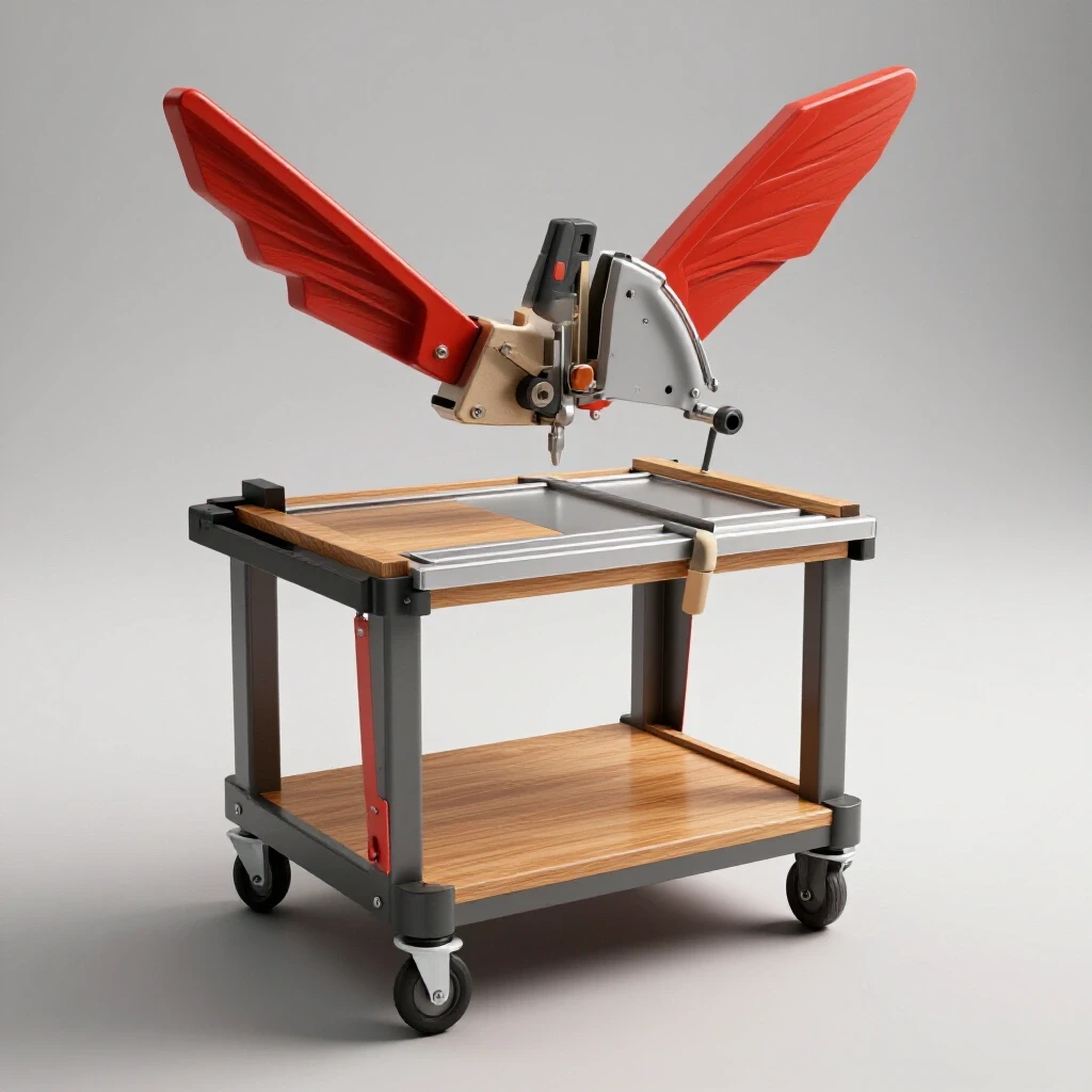
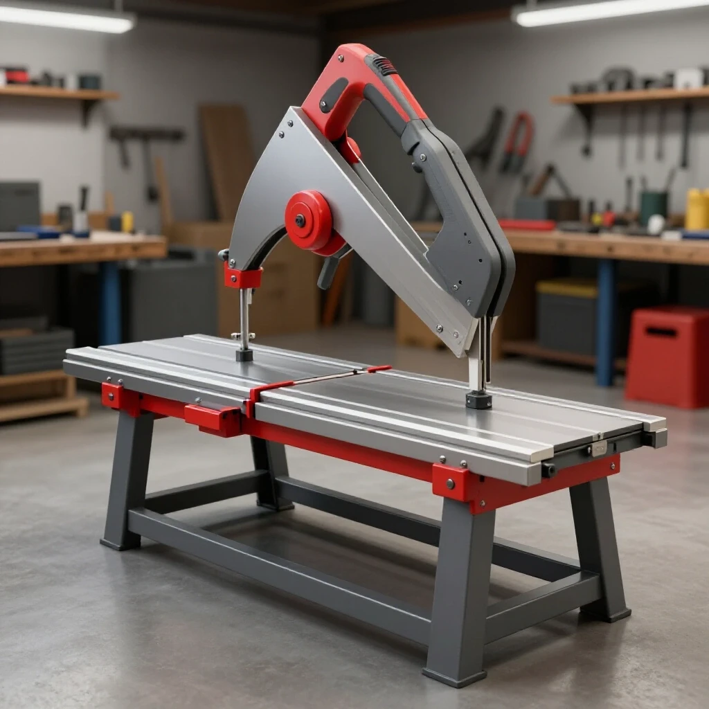
A shop station for your primary saw needs to be more than just a table on wheels. It serves as the backbone of every other project you will ever build. If the support wings are not level with the saw bed, or if the frame is twisted because of poor weld sequencing, every piece of tube or angle you cut will be slightly off. This guide focuses on the technical realities of constructing a stable, mobile cutting platform that stays true, even after the last weld cools.
Essential Layout and Material Preparation Principles
Proper preparation is the foundation of any custom fabrication project. It involves more than just reading a tape measure; it requires accounting for the physical space the cutting tool removes and ensuring the raw stock is prepared for a clean electrical connection during welding.
Before I even strike an arc, I spend a significant amount of time on the layout. In my shop, I follow the “measure twice, cut once, and then verify” rule. For a mobile cutting station, you are typically working with 1.5-inch or 2-inch square tubing. When you plan your cutting list, you must account for the kerf. The kerf is the width of the material removed by the saw blade itself. If you are using an abrasive saw, that blade might be 1/8-inch thick. If you ignore this across ten cuts, your final assembly could be over an inch short of your target.
I also focus heavily on material prep. Mill scale is the dark, flaky layer on hot-rolled steel that acts as an insulator. If you do not grind it back to shiny metal where your tacks and welds will go, you risk poor penetration and a brittle joint. I aim for a “bright metal” finish at least one inch away from every joint. This ensures the arc stays stable and the weld puddle flows predictably, which is vital for maintaining dimensional tolerances.
Understanding Kerf and Cutting Allowances
Kerf is the void left by a cutting tool, and failing to account for it is the leading cause of “short” frames. In metalwork, different tools create different widths of waste, which must be added to your total material order to avoid running out of stock.
When I am planning a frame for a mobile workstation, I use a cutting calculator or a simple spreadsheet to track my yields. If I have a 20-foot stick of tubing and I need four 5-foot pieces, I will actually end up short because of the kerf. Below is a breakdown of what to expect from various cutting methods.
| Cutting Tool Type | Typical Kerf Width (Inches) | Impact on 10 Cuts | Recommended Allowance |
|---|---|---|---|
| Abrasive Chop Saw | 0.125 (1/8″) | 1.25″ | Add 1.5″ per 10 cuts |
| Cold Saw (Carbide) | 0.090 (3/32″) | 0.90″ | Add 1.0″ per 10 cuts |
| Portable Bandsaw | 0.035 (1/32″) | 0.35″ | Add 0.5″ per 10 cuts |
| Plasma Cutter | 0.060 – 0.100 | 0.60″ – 1.0″ | Varies by tip size |
- Pro Tip: Always mark your cut line and then place the blade on the “waste side” of the line. This ensures the part you keep is the exact dimension you measured.
Constructing the Main Chassis Frame
The main chassis is the central hub that supports the weight of the saw and provides the mounting points for the wheels and extension arms. It must be perfectly square in all three planes to ensure the tool functions correctly and the wings align.
I start the main frame by laying out the perimeter on a flat surface. In many home garages, the concrete floor is not actually flat; it usually slopes for drainage. To combat this, I use a pair of heavy-duty sawhorses and two lengths of thick C-channel to create a temporary leveling bed. I check the level across the “rails” and then lay my tubing on top.
Squaring the frame is where most builders struggle. I rely on the 3-4-5 triangle method or by measuring the diagonals. If the measurement from the top-left corner to the bottom-right corner is exactly the same as the top-right to the bottom-left, the frame is square. I aim for a tolerance of +/- 1/16th of an inch. Once square, I use heavy F-clamps to lock the pieces against my leveling rails. This physical restraint is the first line of defense against metal warping solutions.
Tack Welding for Structural Integrity
Tack welds are small, temporary welds that hold the components in place before the final beads are run. They are not just “spots” of metal; they are structural anchors that must be strong enough to resist the cooling forces of the final weld.
I typically place tacks at each corner of a joint. For 2-inch square tubing, a tack should be about 1/4-inch to 3/8-inch long. If the tacks are too small, the heat from the final welding pass will simply melt them, and the frame will pull out of alignment. I always tack the “outside” corners first, re-verify the squareness with a framing square, and then tack the “inside” corners.
- Tack Spacing: For long spans on a mobile cart, I space tacks every 3 to 4 inches.
- Verification: After the first set of tacks, I hit the frame with a rubber mallet if it needs a 1/32-inch adjustment, then I “lock” it with opposite tacks.
Engineering the Wing Support Arms
The wing supports are the defining feature of a high-quality cutting station, providing the necessary surface area to hold 10-foot or 20-foot sticks of steel. These wings must be adjustable to account for the varying heights of different tool bases.
When I designed my most recent station, I chose a folding wing design using heavy-duty hinges. The challenge here is alignment. If the wing is even 1/8-inch lower than the saw’s base, the material will tilt, resulting in an angled cut rather than a 90-degree vertical cut. To solve this, I integrate a leveling bolt system. This consists of a nut welded to the underside of the wing frame with a bolt that acts as an adjustable “stop.”
The wings are typically constructed from lighter-gauge square tubing or angle iron to keep the weight manageable. I use a long straightedge—at least 6 feet—to bridge the gap between the saw’s table and the end of the wing. This allows me to see any “daylight” between the straightedge and the support surface. If there is a gap, I adjust the leveling bolt until the support is perfectly flush.
Precision Alignment for Long Stock
Ensuring the wings are parallel to the saw fence is just as important as ensuring they are level with the table. If the wings are bowed forward or backward, the material will not sit flush against the saw’s fence, leading to inaccurate miter cuts.
I use a string line or a laser level to check the horizontal alignment across the entire 12-to-15-foot span of the opened wings. If I find that the hinges have pulled the wing out of alignment during welding, I use a technique called “heat shrinking.” By applying a small amount of heat with a torch to the side I want the metal to pull toward, and then quenching it with a wet rag, I can move the wing back into the correct position. It is a slow process, but it allows for fine-tuning that mechanical force cannot achieve.
Managing Heat and Weld Sequencing
Weld sequencing is the strategic order in which you apply welds to balance the internal stresses caused by heating and cooling. Every weld you make acts like a tiny, powerful winch, pulling the metal toward the center of the bead.
If you weld all the way around one joint before moving to the next, you are guaranteed to have a warped frame. I use a “staggered” approach. I might weld the top side of the front-left joint, then move to the bottom side of the back-right joint. This distributes the heat across the chassis and allows one area to cool while I work on another. By balancing the “pull” of the welds, I can keep the frame within my 1/16-inch tolerance.
The Science of Thermal Distortion
When steel is heated to its melting point, it expands. As it cools, it contracts more than it expanded, creating a permanent “pull” in the direction of the weld. This is known as angular distortion.
In my workshop jigs and fixtures, I often “pre-set” my joints to account for this. If I know a weld will pull a vertical upright inward by 2 degrees, I will clamp it so it is leaning 2 degrees outward before I weld. As the weld cools, it pulls the piece into a perfect 90-degree angle. This requires experience and a log of how your specific welder and settings affect the material.
| Weld Sequence Step | Location | Purpose |
|---|---|---|
| 1. Primary Tacks | All 4 corners (top) | Establish the basic footprint and verify square. |
| 2. Secondary Tacks | All 4 corners (bottom) | Lock the vertical alignment. |
| 3. Short Beads (1″) | Opposing diagonal corners | Distribute heat and prevent “diamonding.” |
| 4. Vertical Welds | Inside corners | Pulls the joint tight against the horizontal members. |
| 5. Final Caps | Outside faces | Provides structural strength and aesthetic finish. |
Mobility and Hardware Integration
A mobile cart is only as good as its wheels. For a station that carries a heavy saw and potentially hundreds of pounds of steel, the caster selection and mounting strategy are critical for both safety and ease of use.
I always recommend using four swivel casters with total-lock brakes. Total-lock brakes are essential because they lock both the wheel rotation and the swivel mechanism. If the swivel is not locked, the cart will “dance” or shimmy while you are trying to push a heavy piece of steel against the fence. I mount my casters to 1/4-inch thick steel plates, which are then welded to the bottom of the main legs. This provides a much stronger foundation than simply bolting through thin-walled tubing.
Caster Placement and Weight Distribution
The center of gravity changes when the wings are extended. To prevent the cart from tipping when you load a heavy piece of 4-inch C-channel onto an extended wing, the wheel base must be wide enough to remain stable.
- Footprint: I ensure the main cart body is at least 24 inches wide and 30 inches deep.
- Caster Rating: Use casters rated for at least double the expected weight of the cart and saw combined. A typical setup weighs about 150-200 lbs; I use four 300-lb rated casters for a total capacity of 1,200 lbs. This provides a massive safety margin and ensures the wheels don’t develop “flat spots” over time.
Case Study: Recovering from a Twisted Frame
I once worked on a project where the builder had welded the entire top deck of a similar station in one go. The result was a “potato chip” frame that sat on only three wheels. This is a common issue for those new to custom fabrication projects.
To fix it, we had to use a combination of mechanical force and heat. We clamped the high corner down to a heavy welding table and used an oxy-acetylene torch to heat the opposite corner’s joints to a dull red. By allowing it to cool while under the pressure of the clamps, we “relieved” the stress. It took three iterations of heating and cooling to get the frame flat again. This experience reinforced why I now emphasize weld sequencing layout so heavily; it is much easier to prevent a twist than it is to fix one.
Lessons from the Build Log
- Never skip the tacks: Even if you think the clamps are holding it, the heat will move the metal.
- Check square after every four inches of weld: Don’t wait until the end to find out you’re 1/4-inch off.
- Cooling matters: Do not quench your welds with water to speed things up; this can make the steel brittle. Let it air cool naturally.
Actionable Framework for Your Build
To help you stay organized during the fabrication process, I have developed a checklist that I use for almost every workshop fixture I build. Following this sequence helps manage the “building anxiety” that comes with complex layouts.
- Finalize the Blueprint: Determine the height of your saw’s table. Your cart height + caster height + saw table height should equal a comfortable working height (usually 36-40 inches).
- Cut and Deburr: Cut all pieces according to your list, accounting for the 1/8-inch kerf. Use a flap disc to remove all mill scale and burrs.
- The Reference Surface: Find the flattest spot in your shop or set up leveling rails.
- The “Box” Setup: Lay out the main frame, square it using diagonals, and apply tacks to all top corners.
- The Flip: Flip the frame over, re-verify square, and tack the bottom.
- Weld Sequence: Follow the diagonal staggered pattern. Weld 1-2 inches at a time, moving to the opposite side of the frame between beads.
- Wing Fabrication: Build the wings separately, ensuring they are flat. Use a jig if you have enough scrap material.
- Hinge and Leveler Install: Clamp the wings in the “up” position using a straightedge to align them with the saw table before welding the hinges.
- Caster Mounting: Weld the base plates and bolt the casters on once the frame is cool to the touch.
Practical Benchmarks for Success
How do you know if your build is high-quality? I look for these specific benchmarks once the project is finished and the metal has reached room temperature.
- The “Rock” Test: With the brakes off, the cart should sit on all four wheels without any wobbling. If it wobbles, the frame is twisted.
- The Straightedge Test: A 6-foot level placed across the saw and the wings should show no gaps larger than 1/32-inch at any point.
- The Square Cut: Cut a piece of 2×2 square tubing. Use a precision machinist square to check the cut. If it’s perfectly square, your wing alignment and saw mounting are correct.
Building a precision tool station is a rite of passage for any fabricator. It forces you to deal with the realities of metal movement and rewards you with a tool that makes every subsequent project easier. By focusing on the layout, respecting the heat, and following a disciplined weld sequence, you can build a workstation that remains a reliable fixture in your shop for decades.
Frequently Asked Questions
How do I prevent the support wings from sagging over time?
Sagging is usually caused by undersized hinges or a weak attachment point. Use hinges with a thick pin (at least 1/2-inch) and weld them to a reinforced section of the frame. Additionally, the adjustable leveling bolt acts as a mechanical stop that takes the load off the hinge pin, preventing long-term deformation.
What is the best way to ensure the saw stays centered on the cart?
I recommend welding small “tabs” or a shallow angle-iron “cradle” onto the top of the cart that matches the footprint of your saw’s base. This allows you to bolt the saw down securely while ensuring it returns to the exact same position if you ever need to remove it for maintenance.
Should I use square tubing or angle iron for the main frame?
Square tubing (typically 14-gauge or 11-gauge) offers much higher torsional rigidity than angle iron. This means the frame is less likely to twist under the weight of the saw or when moving over uneven shop floors. Angle iron is acceptable for the wing supports where weight reduction is a priority.
How much weight can a typical DIY folding wing support?
If built with 1-inch square tubing and a 1/2-inch hinge pin, a 4-foot wing can easily support 50-75 lbs at its furthest point. For significantly heavier loads, such as thick-walled 6-inch pipe, you should incorporate a “swing-out” leg that transfers the weight directly to the floor.
Why does my frame pull out of square even when I use heavy clamps?
Clamps can only resist so much force. When a weld cools, the shrinkage force can exceed several thousand pounds per square inch. If you weld one side completely while it is clamped, it may look square, but the moment you release the clamps, the internal stresses will “spring” the frame out of shape. Staggered welding is the only real solution.
How do I account for the height of the casters in my plan?
Always purchase your casters before finalizing your cutting list. Measure from the floor to the top of the mounting plate. Subtract this value, along with the thickness of your saw’s base, from your desired working height to determine the length of your vertical leg members.
Can I build this with a flux-core welder, or do I need MIG?
You can certainly use flux-core, but be aware that it produces more heat and more “spatter” than MIG. Because flux-core runs hotter, you must be even more diligent with your weld sequencing to prevent warping. Ensure you clean the slag thoroughly between passes to inspect for weld integrity.
What is the ideal length for the wing supports?
For most home shops, wings that extend 4 to 5 feet on either side are ideal. This provides a total support span of 10 to 12 feet. If you frequently work with 20-foot sticks, you will need to either build longer wings with support legs or use standalone roller stands in conjunction with your cart.
How do I fix a wing that is slightly tilted forward?
This is where the leveling bolt system is invaluable. By adjusting the bolt, you can change the angle at which the wing rests. If the wing is tilted horizontally (not parallel to the fence), you may need to grind the welds on one side of the hinge, reposition it, and re-weld using a string line as a guide.
Is it necessary to weld a bottom shelf, or can I leave it open?
A bottom shelf made of expanded metal or a thin steel sheet adds significant structural rigidity to the frame. It acts as a “diaphragm” that prevents the legs from splaying and keeps the frame from “diamonding” over time. Plus, it provides a great place to store off-cuts and tools.
(This article was written by one of our staff writers, Robert Kline. Visit our Meet the Team page to learn more about the author and their expertise.)