How to Build a Stable Rolling Tool Cart Frame (DIY Tutorial)
I have spent the better part of two decades chasing ghosts in the machine. In my 15 years as a diagnostic specialist, I have learned that a machine is only as reliable as the foundation it sits upon. I remember a specific case in a high-production mill where a precision lathe was producing a finish that looked like a plowed field. The operators had replaced the spindle bearings twice, adjusted the gibs, and swapped out every cutting tool in the crib. When I arrived, I didn’t look at the headstock first. I looked at the floor. The lathe was mounted on a poorly fabricated rolling base that was flexing under the weight of the carriage travel. The “tool chatter” wasn’t a mechanical failure of the lathe; it was a resonance issue caused by an unstable, poorly braced frame.
This experience taught me that in metalworking, we often mistake structural instability for mechanical failure. Whether you are building a mobile base for a heavy welder or a precision tool stand, the diagnostic process begins with understanding how forces move through steel. We aren’t just sticking metal together; we are managing harmonics, thermal expansion, and load distribution. If your equipment base isn’t dead-flat and rigid, every diagnostic step you take thereafter will be built on a lie.
Establishing the Foundation: Why Structural Rigidity Prevents Diagnostic Errors
Structural rigidity refers to the ability of a fabricated frame to resist deformation under load and vibration. In a workshop environment, a rigid base ensures that precision tools maintain their alignment and that external vibrations do not interfere with delicate machining or welding processes.
When a mobile unit is under-built, it acts like a tuning fork. Every rotation of a motor or movement of a slide sends vibrations through the frame. If those vibrations hit a resonant frequency, you get tool chatter—that high-pitched scream that ruins surface finishes and destroys carbide inserts. To solve this, we must look at the frame as a complete system. I use a systematic diagnostic approach: observation of the vibration, isolation of the flexing member, and variable control through bracing.
A common mistake I see is using thin-walled tubing for heavy equipment. While it is easier to cut, it lacks the mass and stiffness required to dampen motor harmonics. When I diagnose a “shaking” machine, the first thing I check is the wall thickness of the base. For a stable workshop platform, 11-gauge (1/8 inch) square tubing is often the minimum entry point for structural stability.
Systematic Planning: Material Selection and Load Path Analysis
Load path analysis is the process of tracing how weight and force travel from the top of a structure down to the floor. By understanding these paths, you can identify potential points of failure or flexing before you ever strike an arc.
Before cutting into your steel, you need to calculate the static and dynamic loads. A static load is the weight of the tool sitting still. The dynamic load includes the forces generated during operation—like the torque of a motor or the impact of a hammer. If the frame isn’t designed to transfer these forces directly to the casters, the steel will eventually fatigue and crack at the weld joints.
I prefer square or rectangular tubing over angle iron for rolling bases. Tubing offers superior torsional rigidity, meaning it resists twisting much better than open-faced steel. When you are troubleshooting a frame that won’t sit level, the culprit is often a lack of torsional stiffness.
| Material Type | Wall Thickness | Best Use Case | Diagnostic Risk |
|---|---|---|---|
| 14-Gauge Square Tubing | 0.083″ | Light carts, hand tool storage | High flex under heavy machinery |
| 11-Gauge Square Tubing | 0.120″ | Welders, small lathes, mills | Standard for most shop builds |
| 3/16″ Rectangular Tubing | 0.187″ | Heavy industrial equipment | Overkill for small tools; heavy to move |
| 1/4″ Structural Angle Iron | 0.250″ | Bracing and caster plates | Prone to twisting if not cross-braced |
Troubleshooting Weld Porosity and Joint Integrity in Structural Frames
Weld porosity is a defect characterized by small pits or holes in the weld bead, usually caused by trapped gas. In a structural frame, porosity acts as a stress riser, significantly weakening the joint and leading to eventual structural failure.
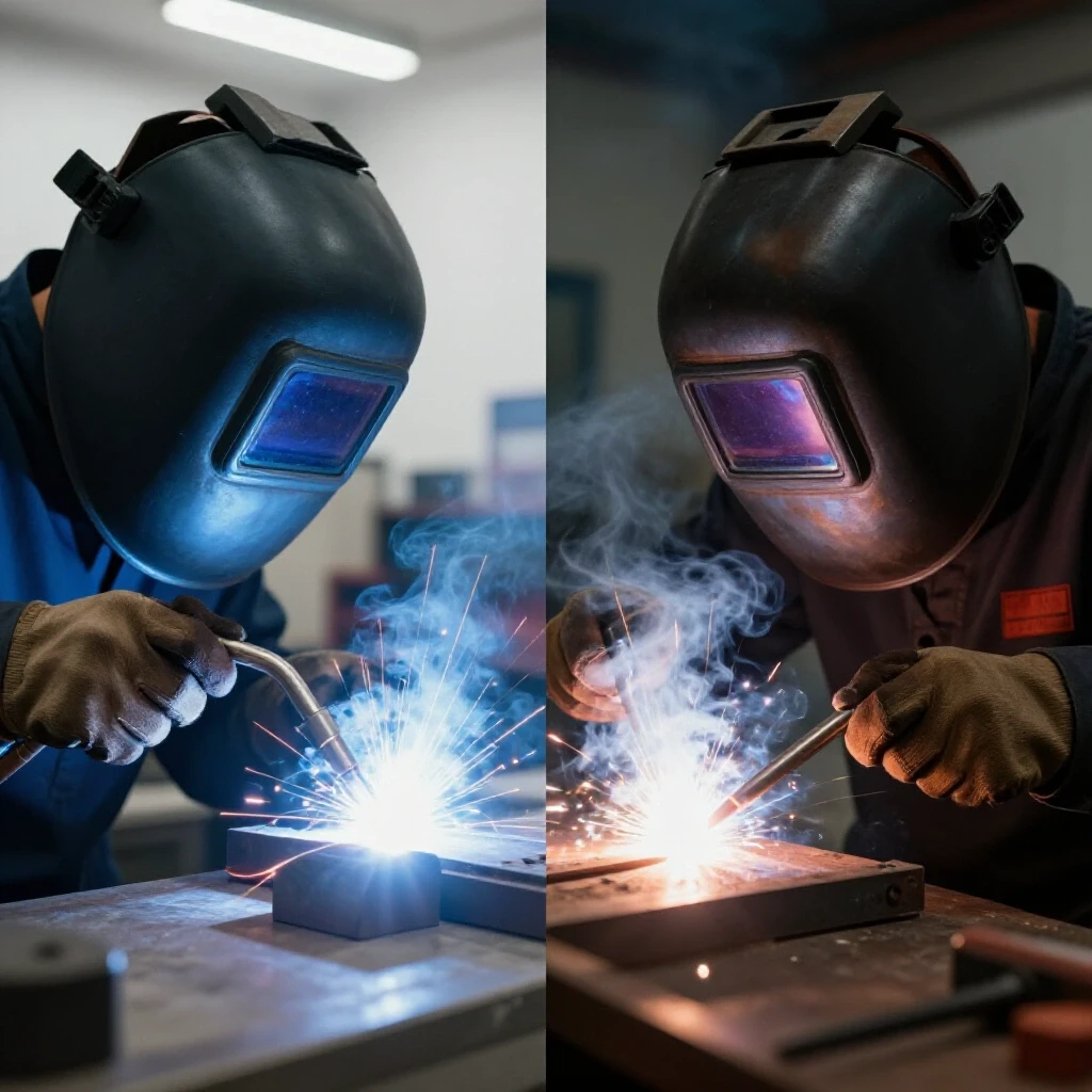
When I’m inspecting a frame and see porosity, I don’t just grind it out and weld over it. I treat it as a symptom of a process failure. Is the shielding gas flow too high, causing turbulence? Is there mill scale or oil inside the tubing that is outgassing? If you are using MIG (GMAW), check your flow rate. I typically set my regulator between 20 and 25 cubic feet per hour (CFH) for indoor shop work. Any higher, and you risk pulling atmospheric air into the weld pool.
TIG (GTAW) is even more sensitive. If I encounter porosity while TIG welding a frame, I immediately check the back side of the joint. Square tubing often traps air; as the metal heats up, that air expands and pushes through the molten puddle. Drilling a small “weep hole” in a non-structural area can allow this pressure to escape, ensuring a clean, sound weld.
- Check gas coverage: Ensure your nozzle is clean and your flow rate is consistent.
- Surface prep: Grind back mill scale at least one inch from the weld zone.
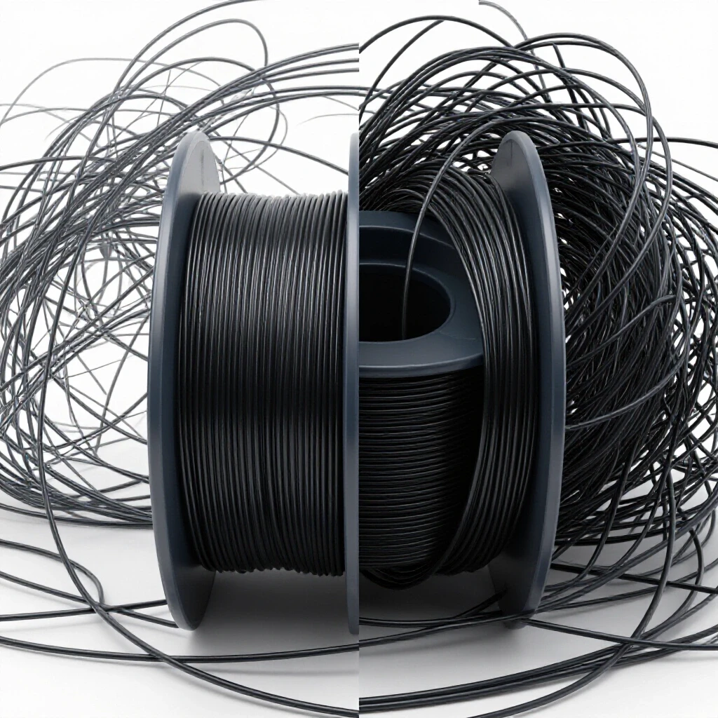
- Consumable check: Use dry, clean filler wire. Rust on a MIG wire spool is a one-way ticket to porosity.
- Joint fit-up: Gaps larger than 1/16 inch increase the risk of atmospheric contamination.
Eliminating Structural Warping Through Heat Management
Structural warping is the unintended distortion of metal caused by the uneven heating and cooling cycles of the welding process. This can lead to a “rocking” frame that refuses to sit flat on all four casters, regardless of how level the floor is.
Every time you lay a bead, the cooling metal shrinks. This shrinkage pulls the rest of the frame with it. To diagnose and prevent this, I use a strict tacking sequence. I never weld a single joint to completion before the rest of the frame is tacked. I start by tacking the four corners, then I measure the diagonals. If the diagonals are within 1/32 of an inch, the frame is square.
I also utilize “backstepping” or “stitching.” Instead of one long continuous bead, I weld in short 2-inch segments, jumping from one side of the frame to the opposite. This distributes the heat input more evenly. If I find a frame has already warped, I use a torch to “heat shrink” the opposite side, pulling it back into alignment—a technique that requires patience and a steady hand.
Caster Geometry and Plate Alignment: Resolving the “Death Wobble”
Caster alignment involves ensuring that all four mounting plates are on the same horizontal plane and that the casters are mounted perpendicular to that plane. Misalignment here causes uneven weight distribution, making the cart difficult to steer and prone to vibration.
If you have ever pushed a cart and felt one wheel fluttering or “walking,” you are dealing with a caster alignment issue. This is often caused by the mounting plates warping during welding. Because these plates are usually thicker (1/4 inch or more) than the tubing, they require more heat. That heat pulls the plate into a “cup” shape.
To diagnose this, I use a precision straightedge across the mounting surfaces. If the plates are not co-planar, I use shims between the caster and the plate to bring them back to level. In high-vibration environments, I prefer bolt-on casters over weld-on versions. This allows for easier replacement and fine-tuning of the alignment using 0.002-inch stainless steel shims.
- Verify Planarity: Use a laser level or a long straightedge across all four corners.
- Torque Specs: Ensure mounting bolts are torqued equally to prevent localized stress.
- Caster Rating: Always choose casters rated for 150% of the total expected weight to account for dynamic shifts.
- Swivel Clearance: Check that the swivel radius does not interfere with the frame’s cross-bracing.
Advanced Vibration Dampening: Cross-Bracing and Resonant Frequency
Vibration dampening in fabrication involves adding structural elements that break up long, unsupported spans of metal. This changes the natural frequency of the frame, preventing it from amplifying the vibrations of the tools it supports.
A simple rectangle frame is weak against lateral forces. If you push on the top of a tall tool stand, it will likely sway. This sway is a sign of poor triangulation. By adding diagonal cross-bracing, you turn those rectangles into triangles, which are geometrically rigid. This is essential for resolving tool chatter on machines like bench grinders or small drill presses.
Interestingly, you can diagnose vibration issues using a smartphone. There are several apps that use the phone’s accelerometer to map vibration frequencies. If I see a spike at a specific RPM, I know exactly where the frame needs more mass or more bracing. Adding a 45-degree gusset to the corners of the base frame can often reduce vibration amplitude by over 50%.
Precision Leveling and Squaring: Measuring Workshop Equipment Bases
Precision leveling is the act of ensuring the main load-bearing surfaces of a frame are perfectly horizontal and square. This is critical for machines like lathes or bandsaws, where an unlevel base can lead to “twist” in the machine’s bed, ruining accuracy.
Do not trust your shop floor to be level. Most concrete slabs are poured with a slight pitch for drainage. When I build a rigid support frame, I do the final assembly on a dedicated welding table or a known flat surface. I use a machinist’s level—which is accurate to 0.0005 inches per foot—to check the primary rails.
If you are troubleshooting a machine that is cutting a taper, check the base first. A frame that is twisted by even 0.010 inches can transmit that twist through the machine’s casting. I use adjustable leveling feet on the frame, even if it has casters. Once the cart is moved into position, the leveling feet take the load off the casters and allow for micro-adjustments to the machine’s geometry.
Structural Alignment Checklist
- Diagonal Measurement: Are the corner-to-corner distances within 1/32″?
- Vertical Plumb: Are the vertical legs 90 degrees to the base in both axes?
- Surface Flatness: Does a straightedge show gaps larger than 0.005″ across the top rails?
- Weld Penetration: Are there any visible cold laps or lack of fusion at the root?
- Caster Spin: Do all wheels touch the ground simultaneously on a known flat surface?
Diagnostic Math: Calculating Deflection and Load
Understanding the math behind metal helps you avoid over-engineering or under-building. For a horizontal beam (the top rail of your frame), the deflection (how much it bends) is determined by the load, the span length, and the moment of inertia of the tubing.
If you double the length of a span, the deflection doesn’t just double—it increases by a factor of eight. This is why long, rolling frames often feel “bouncy.” If I am troubleshooting a cart that feels unstable, I look at the longest unsupported span. Adding a center leg or a vertical stiffener can solve the issue without requiring heavier, more expensive steel.
For most shop-built frames, you want to keep deflection under 0.001 inches per foot of span under full load. If your lathe weighs 500 lbs and your frame rails are 4 feet long, you need a tubing profile that can handle that 500 lbs without bowing visibly. This is where 2×2 inch square tubing with a 1/8 inch wall usually outperforms 1×1 inch tubing, even if the 1×1 has a thicker wall.
Common Fabrication Pitfalls and How to Avoid Them
Even experienced fabricators can fall into traps when building mobile equipment supports. One of the most common is “over-welding.” It is tempting to run a bead around every single inch of a joint. However, too much weld metal adds unnecessary heat, increasing the risk of warping without adding significant strength. A well-placed 2-inch weld is often stronger than a poor 6-inch weld that has crystallized the base metal.
Another pitfall is ignoring the “center of gravity.” If you build a narrow frame for a top-heavy tool like a drill press, you are creating a tipping hazard. As a rule of thumb, I ensure the base of the frame is at least 1.5 times wider than the widest part of the tool it supports. If I’m troubleshooting a cart that feels “tippy” during movement, I look to move the heavy components (like motors or transformers) as low as possible in the frame.
- Mistake: Welding casters directly to thin-walled tubing.
- Fix: Always use a 1/4″ spreader plate to distribute the load.
- Mistake: Using “mystery metal” from the scrap pile.
- Fix: Stick to known A36 structural steel for predictable welding and strength.
- Mistake: Forgetting to deburr the inside of tubing.
- Fix: Burrs can interfere with fit-up, leading to gaps and poor weld penetration.
Next Steps for a Stable Workshop Build
Building a truly stable, vibration-resistant frame is a masterclass in systematic fabrication. You start with a plan, you control your variables (heat and fit-up), and you verify your results with precision tools.
If you are currently struggling with a machine that won’t hold its calibration, I challenge you to look at the frame it sits on. Put a dial indicator on the machine bed and push against the frame. If that needle moves more than 0.002 inches, your frame is the problem, not your machine. Your next step should be to identify where the flex is occurring and apply the triangulation and bracing techniques we’ve discussed.
FAQ: Troubleshooting Structural Fabrication
How do I know if my weld porosity is structural or just cosmetic? In a structural frame, there is no such thing as “cosmetic” porosity. Any hole in the weld bead is a void that can harbor moisture (leading to internal rust) or act as a starting point for a crack. If you see more than two or three pinholes in a inch of weld, grind it out and restart.
Why does my frame rock on three wheels even though I measured everything? This is almost always due to “diagonal pull” during welding. As the welds on one corner cooled, they pulled that corner up. To fix this without cutting the frame apart, you can often use a heavy C-clamp to “cold-bend” the frame back into alignment, or use shims on the casters.
What is the best way to stop tool chatter on a mobile cart? Increase the mass and the rigidity. You can fill the lower legs of the tubing with dry sand to dampen high-frequency vibrations, but the most effective fix is adding diagonal bracing to stop the frame from swaying.
Can I use TIG welding for a heavy equipment frame? Yes, TIG provides excellent control and very strong welds. However, it is much slower than MIG and puts more localized heat into the metal, which can increase warping if you aren’t careful with your sequence.
How thick should my caster mounting plates be? For most workshop tools, 1/4 inch (0.250″) plate is the standard. It provides enough thickness to tap threads if you don’t want to use nuts, and it resists bending under the leverage of the caster’s swivel.
Why do my welds crack after a few months of use? Cracking is usually a sign of “brittle failure” or “fatigue.” If the frame is flexing too much, the welds are constantly being bent back and forth. Eventually, they work-harden and snap. The solution is to add bracing to stop the flexing.
Does it matter which way I orient rectangular tubing? Yes. Rectangular tubing is much stronger when the “long” side is vertical. This is called the “strong axis.” If you lay it flat, it will deflect much more under the same load.
How do I check for squareness on a large frame? The most accurate way is the “3-4-5” rule or by measuring the diagonals. On a rectangle, the two diagonal measurements (corner to corner) must be exactly the same for the frame to be square.
What shielding gas is best for MIG welding these frames? For carbon steel tubing, a 75% Argon / 25% CO2 mix (C25) is the industry standard. It provides a good balance of penetration and minimal spatter.
How can I prevent rust inside the tubing? After welding is complete and the frame has cooled, you can spray a light coat of oil or a specialized frame coating inside the tubes through the weep holes. Then, cap the ends with plastic plugs or weld-on end caps.
(This article was written by one of our staff writers, Paul Whitaker. Visit our Meet the Team page to learn more about the author and their expertise.)