How to Build a Safe Battery Charging Station Rack (DIY Plan)
I remember the first utility trailer I built in my backyard about a decade ago. I had measured every piece of angle iron to the sixteenth of an inch. My magnets were square, and my floor was level. But the moment I finished the final weld on the rear gate, the entire frame twisted. One corner lifted nearly three-quarters of an inch off the ground. It was a humbling reminder that steel is a living thing when you introduce heat. If you have ever felt that sinking feeling in your gut when a project warps out of square, you are not alone.
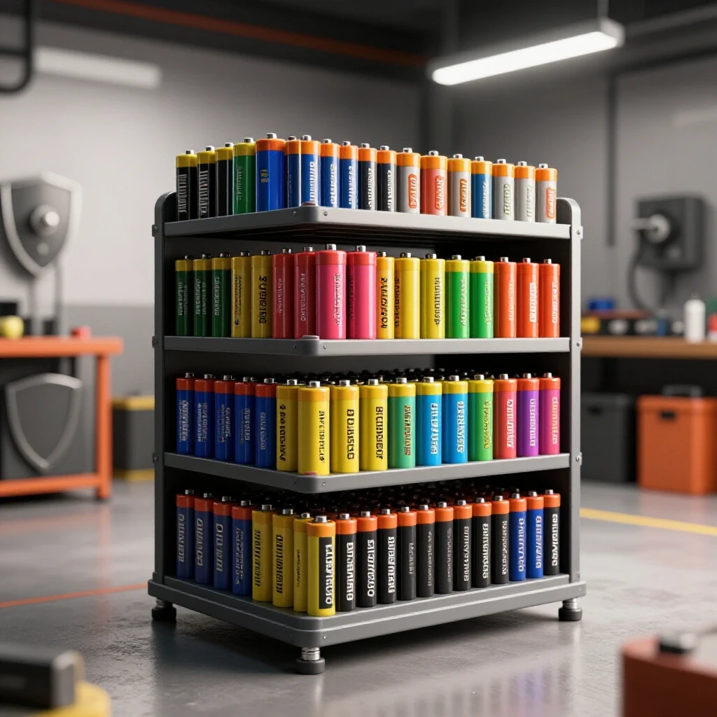
Fabricating a heavy-duty storage frame for power tool chargers is a perfect project to master the art of heat control and layout precision. These units need to be sturdy enough to hold several pounds of batteries while allowing enough airflow to prevent heat buildup. In this guide, I will walk you through the process of building a ventilated, wall-mounted rack using square tubing and expanded metal. We will focus on the technical side of custom fabrication projects, ensuring your frame stays straight and your cuts remain accurate from the first spark to the final coat of paint.
Designing the Cut List and Calculating Kerf Allowances
Planning a layout requires more than just a sketch on a napkin; it involves accounting for the physical space your tools occupy during the process. Before you strike an arc, you must create a detailed cut list that accounts for material thickness and the width of your saw blade.
When I plan a project, I start by defining my outer dimensions. For a standard tool organization rack, a width of 36 inches and a height of 24 inches is common. However, if you are using 1-inch square tubing, you cannot simply cut four pieces at those lengths. You have to account for the overlap at the corners. I prefer “butt joints” for these frames because they are easier to square than 45-degree miters. If your top rail sits on top of your side rails, your side rails must be 2 inches shorter than the total height.
One of the most common layout errors is ignoring the “kerf.” The kerf is the width of the material removed by the saw blade. A standard abrasive chop saw blade is about 3/32 of an inch thick, while a cold saw or a bandsaw might be closer to 1/16 of an inch. If you make ten cuts without accounting for a 1/16-inch kerf, your final piece will be over half an inch short.
Material Kerf Allowances by Cutter Type
| Cutting Tool | Average Kerf Width | Dimensional Impact per 10 Cuts | Recommended Use Case |
|---|---|---|---|
| Abrasive Chop Saw | 3/32″ (0.093″) | 15/16″ | Rough framing, thick plate |
| Portable Bandsaw | 0.025″ – 0.035″ | ~5/16″ | Precision tubing, thin wall |
| Plasma Cutter | 0.040″ – 0.060″ | ~1/2″ | Plate steel, custom shapes |
| Oxy-Acetylene Torch | 1/8″ – 3/16″ | 1.25″ – 1.87″ | Heavy structural demolition |
To maintain a tolerance of +/- 1/16th inch, I always mark my line and then cut on the “waste side” of that line. This ensures the blade eats the scrap material rather than your measured piece. Building this habit is the first step toward high-quality metal layout tips that save you money on wasted steel.
Managing Cut Accuracy and Material Squaring
Getting a project to sit flat on a wall starts with the ends of your tubes being perfectly 90 degrees. Even a one-degree error on a 24-inch vertical rail can throw the bottom of the rack off by nearly half an inch.
I always check my chop saw for square before a big project. I don’t trust the built-in gauges on the saw base. Instead, I use a machinist’s square to verify the blade is 90 degrees to the fence and 90 degrees to the table. If your saw is cutting “long” on one side, your joints will have gaps. Gaps are the enemy of a straight build because they require more weld metal. More weld metal means more heat, and more heat leads to metal warping solutions being needed later.
When you are ready to layout your frame on the bench, use the “3-4-5 rule” to verify squareness. Measure 3 inches from a corner on one side and 4 inches on the other. The diagonal between those two points must be exactly 5 inches. For a larger frame, you can use 18, 24, and 30 inches. This is a basic engineering principle that works regardless of the size of your custom fabrication projects.
- Measure your diagonals: If the distance from the top-left corner to the bottom-right corner matches the top-right to bottom-left, the frame is square.
- Clean your ends: Use a flap disc to remove the “burr” left by the saw. A burr can prevent a joint from closing tightly.
- Verify material flatness: Sight down the length of your tubing. If it has a natural “bow,” place the bow facing inward so the welding heat can pull it straight.
Building Workshop Jigs and Fixtures for Frame Alignment
A jig is a temporary structure or tool used to hold your workpieces in a fixed position during the fabrication process. Without workshop jigs and fixtures, you are fighting the natural tendency of steel to move as it heats and cools.
For a wall-mounted rack, I often build a simple “cleat jig” on my welding table. I take scraps of angle iron and tack them directly to the table surface to create a perimeter that my frame pieces can slide into. This acts as a physical stop. If you don’t want to weld to your table, you can use heavy-duty C-clamps and “1-2-3 blocks” to create a rigid boundary.
The goal of a fixture is to provide mechanical resistance against “angular pull.” When you weld a joint, the liquid metal shrinks as it solidifies. This shrinkage acts like a tiny winch, pulling the two pieces of metal toward the side where the weld was placed. By clamping the pieces firmly to a heavy table or jig, you force the metal to stretch slightly as it cools rather than allowing it to bend the entire frame.
Fixturing Span and Clamp Recommendations
- Clamp Spacing: Place a clamp within 2 inches of every corner joint.
- Tack Spacing: For 1-inch tubing, use four small tacks (one on each side of the tube) before running a full bead.
- Support Blocks: Use 1/4-inch shims to lift the tubing off the table if you need to weld the underside without flipping the piece.
- Heat Sinks: Placing a thick copper or aluminum block behind a weld area can help dissipate heat and reduce distortion.
Tack Welding Strategies for Structural Stability
A tack weld is a small, temporary weld used to hold components in place before the final welding begins. Many beginners make the mistake of making their tacks too small or too large.
If a tack is too small, the cooling forces of the first full bead will snap it, and your frame will spring out of alignment. If it is too large, it will be difficult to “consume” into the final weld, leaving a lump in the corner. For 14-gauge square tubing, a tack should be about 1/8 to 3/16 of an inch in diameter. I like to place tacks on the corners of the tubing where the metal is strongest.
The “tack and check” method is the only way to ensure accuracy. I tack one corner, then check for square. Then I tack the opposite corner (diagonally across the frame) and check again. By the time I have eight tacks on a four-sided frame, the structure should be rigid enough to hold its shape, but still flexible enough that I could “cold-set” it (hit it with a dead-blow hammer) if it moved slightly.
- Place your first tack on the “inside” of the corner. This pulls the joint tight.
- Check the diagonal measurements of the frame.
- Place the second tack on the “outside” of the same corner to lock the angle.
- Repeat for all four corners, always checking diagonals after every two tacks.
- Ensure tacks are “flat” enough that they won’t interfere with your final welding torch path.
Weld Sequencing Layout to Control Heat Distortion
Weld sequencing is the specific order in which you apply welds to a structure to balance the internal stresses and minimize overall warping. This is where most custom fabrication projects succeed or fail.
If you weld all the joints on the top of the frame first, the entire rack will “potato chip,” meaning the corners will lift. To prevent this, you must distribute the heat evenly. I use a “back-stepping” or “staggering” technique. I weld one side of a joint, then move to the diagonally opposite corner of the frame and weld the opposite side of that joint.
Think of it like tightening the lug nuts on a car tire. You don’t go in a circle; you go in a star pattern. This balances the “pull” of the cooling metal. Because the rack will hold heavy chargers, these welds need to be structural, but they don’t need to be massive. A 1/8-inch fillet weld is usually more than enough for 1-inch tubing.
Weld Sequencing and Distortion Control Table
| Sequence Step | Action | Purpose |
|---|---|---|
| 1 | Tack all corners | Establishes basic geometry |
| 2 | Weld inside corners (Top) | Pulls joints tight and square |
| 3 | Weld outside corners (Bottom) | Counters the pull from Step 2 |
| 4 | Weld vertical faces (Left) | Locks the vertical alignment |
| 5 | Weld vertical faces (Right) | Finalizes the structural box |
| 6 | Allow to air cool | Prevents brittle “quench” cracks |
Never use water to cool your welds. This “quenching” can make the steel brittle and actually cause more warping due to the sudden temperature drop. Let the frame sit until you can touch it with a gloved hand before removing it from the clamps or jig.
Structural Considerations for Ventilation and Weight
A rack for power tool batteries isn’t just a shelf; it’s a functional piece of workshop equipment. Chargers generate heat, and if you mount them to a solid plate, that heat gets trapped. This is why I recommend using expanded metal for the “floor” of your rack.
Expanded metal allows for 360-degree airflow around the chargers. When you weld expanded metal to your frame, you have to be careful. The thin strands of the mesh melt much faster than the thick walls of the tubing. I set my welder for the tubing thickness and “flick” the arc onto the mesh for just a fraction of a second.
For the mounting points, I suggest drilling 3/8-inch holes through the back vertical rails. Since most wall studs are 16 inches apart, your frame should ideally be 32 or 48 inches wide to hit two or three studs. If your rack is 36 inches wide, you will need to weld a horizontal “mounting strap” (1/8-inch flat bar) across the back so you can lag-bolt it into the studs regardless of where they land.
- Airflow: Ensure at least 2 inches of clearance between the back of the charger and the wall.
- Cord Management: Weld small “rings” or “hooks” made from 1/4-inch round bar to the underside of the frame to keep power cords organized.
- Weight Capacity: A frame made from 1-inch 14-gauge tubing can easily support 100+ lbs if the welds are sound and it is bolted to studs.
Correcting Heat Distortion and Final Straightening
Even with the best weld sequencing layout, some movement is inevitable. If you pull the frame off the table and find it has a slight “rock” to it, don’t panic. This is where the prototype technician’s “tricks of the trade” come in.
One method is “flame straightening,” though I usually save that for thicker plate. For light tubing, you can often use a “cold-straightening” technique. If the frame is twisted, I will clamp one end to the table and use a long pry bar (or a second piece of tubing) to gently twist the frame in the opposite direction. Steel has an “elastic limit.” You have to bend it just past the point of being straight so that when it “springs back,” it lands in the correct position.
Another trick is to use a “shrink weld.” If a rail is bowed outward, you can run a quick bead of weld on the “outside” of the bow. As that bead cools, it will shrink and pull the rail back toward the center. This is a common metal warping solution used in chassis fabrication.
- Identify the high spot: Lay the frame on a known flat surface (like a cast-iron table).
- Apply pressure: Use a heavy weight or a clamp to push the high spot down.
- Heat if necessary: A propane torch can soften the metal slightly to make it more receptive to bending.
- Re-measure: Always check your diagonals and flatness after every adjustment.
Finishing and Fire-Resistant Coating
The final step is protecting your work. Because this rack will be near electrical components, I avoid heavy oil-based paints that might be flammable if a charger were to fail. Instead, I prefer a high-quality powder coat or a specialized fire-resistant “intumescent” paint if the rack is in a high-risk area.
Before painting, use a flap disc (60 or 80 grit) to smooth out your welds. This isn’t just for looks; it removes “stress risers” (tiny cracks or notches) that could eventually lead to a weld failure under the vibration of a workshop environment. Wipe the entire frame down with acetone or denatured alcohol to remove the “mill scale” and any oils from your hands.
For the mounting surface, I often line the back of the rack with a piece of 1/4-inch cement board or a thin sheet of aluminum. This provides an extra layer of fire protection between the chargers and the garage wall. It’s a small detail that separates a “weekend project” from a professional-grade workshop fixture.
Actionable Framework for Your Build
To help you stay on track, I have put together this checklist. I use a similar log for every custom chassis I build to ensure I don’t skip a critical alignment step.
- Cut Verification: Measure all pieces twice. Mark the “waste side” of the line.
- Edge Prep: Grind a 30-degree bevel on pieces thicker than 1/8 inch. Remove all burrs.
- Jig Setup: Clamp your perimeter stops to the table. Verify square with the 3-4-5 rule.
- Tack Sequence: Top-left inside, bottom-right inside, top-right inside, bottom-left inside.
- Diagonal Check: Ensure the difference between diagonals is less than 1/16th inch.
- Weld Pass 1: Weld all horizontal joints on the “top” face using a staggered pattern.
- Weld Pass 2: Flip the frame and weld the “bottom” face.
- Weld Pass 3: Weld the “vertical” faces (sides of the tubes).
- Cooling Phase: Let the frame sit for 20 minutes. Do not move it.
- Final Straightening: Check for “rocking” on the table and adjust if needed.
Conclusion
Building a straight, durable metal frame is a game of managing physics. You are fighting the thermal expansion and contraction of steel at every step. By using a disciplined weld sequencing layout and investing time in your workshop jigs and fixtures, you can overcome the common pitfalls of metal warping.
The key is patience. It is tempting to weld the whole frame in one go, but the ten minutes you save in welding will cost you two hours in straightening. Take your time with the layout, trust your measurements, and always keep your heat in check. Your workshop will be safer, more organized, and you’ll have the satisfaction of knowing your project was built to professional standards.
FAQ: Frequently Asked Questions
Why does my frame always warp even when I use heavy clamps?
Clamps provide mechanical resistance, but they cannot stop the molecular-level shrinkage of cooling steel. If the internal stresses are high enough, the metal will simply bend once the clamps are removed. The solution is to balance the “pull” by welding on the opposite side of the joint or using a staggered weld sequence to distribute heat.
What is the best material for a shop-built charging rack?
For most DIYers, 1-inch square mild steel tubing with a 14-gauge (0.083″) wall thickness is the “sweet spot.” It is easy to weld with a standard MIG machine, strong enough to hold significant weight, and light enough to mount on a wall easily.
How do I calculate the kerf for my specific saw?
Take a scrap piece of metal and measure it exactly (e.g., 5.00 inches). Make a cut through the middle. Measure the two remaining pieces and add them together. The difference between the original 5.00 inches and the sum of the two pieces is your exact kerf width.
Should I weld the expanded metal mesh before or after the main frame?
Always weld the main frame first. The frame provides the structural rigidity. If you try to weld the mesh in while the frame is only tacked, the tension of the mesh cooling can pull the frame out of square.
Can I build this project with a 110v welder?
Yes. 14-gauge tubing is well within the capabilities of a 110v MIG or flux-core welder. Just ensure you are plugged into a 20-amp circuit to avoid tripping the breaker during long weld passes.
How do I fix a frame that is “diamonded” (out of square)?
If the frame is diamonded, you can use a ratcheting cargo strap (or a “come-along”) across the long diagonal. Tighten the strap until the diagonals match, then add “gussets” (triangular plates) in the corners to lock it into the correct shape.
Is it better to miter the corners or use butt joints?
Butt joints are generally better for beginners because they are easier to cut accurately. Miters require two perfect 45-degree cuts; if either is off by half a degree, the gap will be impossible to close. Butt joints only require 90-degree cuts, which are easier to verify.
How many mounting points do I need for a 3-foot rack?
I recommend at least four mounting points. Two should be at the top and two at the bottom, spaced 16 or 32 inches apart to hit wall studs. Use 5/16-inch or 3/8-inch lag bolts that penetrate at least 2 inches into the wood stud.
What is “angular pull” in welding?
Angular pull is the distortion that happens when a weld bead is placed on one side of a joint. As the weld cools, it shrinks and pulls the two pieces of metal toward the weld. You can compensate for this by “pre-setting” the pieces a few degrees in the opposite direction.
Do I need to grind my welds flat?
For a tool rack, it is mostly an aesthetic choice. However, if you are mounting chargers flush against the metal, you will need to grind the welds on the mounting surface so the chargers sit flat. Be careful not to “thin out” the base metal too much when grinding.
(This article was written by one of our staff writers, Robert Kline. Visit our Meet the Team page to learn more about the author and their expertise.)