How to Double-Check Your Fabrication Drawings (Checklist)
During my first few years on the shop floor, I spent a lot of time fixing mistakes that could have been avoided with a pencil and a ruler. I remember a specific project involving a heavy-duty engine hoist frame. I had followed the sketches I’d scribbled down, but I hadn’t double-checked the hole centers for the main pivot bolt. When I finished welding the thick plate steel, the bolt wouldn’t pass through. I had to grind out structural welds and start over, wasting hours of work and expensive material. That experience taught me that the most important part of fabrication happens before you ever strike an arc or start a saw.
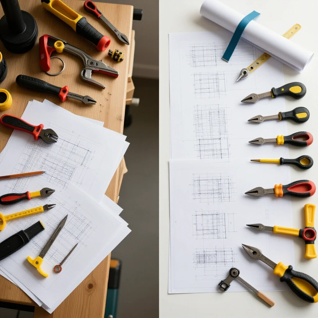
I have spent 14 years as a mechanical engineer and fabricator, and I have learned that a drawing is more than just a picture. It is a set of instructions that must be verified for accuracy, structural logic, and safety. If the plan is wrong, the metal will be wrong, and the final structure could be dangerous. My goal is to help you look at your project plans with a critical eye. By identifying errors in dimensions, material choices, and weld callouts early, you can ensure your projects are both stable and safe.
Verifying Material Specifications and Yield Strengths
Material verification involves checking that the metal specified in your plans matches the physical loads the project will face. This step ensures you do not substitute a lower-grade steel that might fail under tension or compression. It requires confirming the specific alloy, temper, and thickness before any metal is cut or formed.
When I review a design, I start with the material callouts. If a plan calls for A36 structural steel, I need to know why. A36 has a yield strength of about 36,000 PSI. This is the point where the metal will permanently deform. If the project involves high-stress components, like a trailer tongue, substituting a softer “mild steel” from a local hardware store without checking its specs is a risk. I always look for the ASTM (American Society for Testing and Materials) designation on the plan.
Understanding Tensile and Yield Strength
Tensile strength is the maximum stress a material can withstand while being stretched before it breaks. Yield strength is the point where the metal starts to bend and will not spring back to its original shape. Knowing these numbers helps you determine if the material in your plan can handle the intended weight.
In many garage projects, builders use 1018 cold-rolled steel or A36 hot-rolled steel. Cold-rolled steel generally has a higher yield strength because the rolling process hardens the metal. If your drawing assumes the strength of cold-rolled steel but you buy hot-rolled, your structure might be weaker than you think. I always check the “material notes” section of a drawing to ensure the yield strength matches the load calculations.
Evaluating Material Thickness and Weight
Material thickness directly impacts the stiffness of your build. A common mistake is choosing a gauge that is too thin for the span of the project. This leads to “oil-canning” or buckling under load. I use a decimal-inch standard rather than gauge numbers to avoid confusion. For example, 11-gauge steel is roughly 0.120 inches, but different suppliers may vary slightly.
| Material Type | Yield Strength (PSI) | Common Use Case |
|---|---|---|
| A36 Hot-Rolled Steel | 36,000 | General structural frames |
| 1018 Cold-Rolled Steel | 53,700 | Shafts, pins, and precision parts |
| 6061-T6 Aluminum | 40,000 | Lightweight brackets and plates |
| 304 Stainless Steel | 30,000 | Corrosion-resistant decorative work |
Confirming Linear Dimensions and Tolerance Stack-up
Confirming linear dimensions involves checking every measurement on a drawing to ensure they add up correctly from end to end. This process prevents “tolerance stack-up,” where small errors in individual parts combine to create a large error in the final assembly. It is the most effective way to prevent fitment issues.
I once worked on a large gate frame where each vertical picket was off by just 1/16th of an inch. By the time I reached the end of the 20-foot frame, the last picket was over an inch out of place. This is why I perform a “string check” on my drawings. I add up all the internal dimensions and compare them to the overall “master” dimension. If they don’t match exactly, I know there is a mistake in the math.
The Importance of Geometric Tolerances
Tolerances tell you how much a measurement can vary. In a home shop, you might aim for a tolerance of plus or minus 1/32nd of an inch. If your drawing doesn’t specify this, you might cut parts too loosely, leading to large weld gaps. Large gaps are difficult to fill and often lead to internal weld defects or excessive distortion.
I look for “fit” requirements in the plans. For example, if a pin needs to go through a hole, the hole must be slightly larger than the pin. This is called a clearance fit. If the drawing shows a 1.00-inch pin and a 1.00-inch hole, the parts will not fit together in the real world. I always verify that there is at least 0.010 to 0.020 inches of clearance for moving parts.
Checking for Symmetry and Squaring
Many structural failures occur because a frame was built out of square. I check my drawings for “diagonal measurements.” For any rectangular frame, the distance from the top-left corner to the bottom-right corner must equal the distance from the top-right to the bottom-left. I write these diagonal numbers directly on my plan before I start. This gives me a physical benchmark to check against while I am tack-welding the pieces together.
- Verify overall length against the sum of individual parts.
- Check that hole centers are measured from a single “datum” or starting edge.
- Ensure that wall thicknesses of tubing are accounted for in the total width.
- Confirm that bend allowances are included for any sheet metal parts.
Decoding Weld Symbols for Structural Soundness
Weld symbols are a shorthand language used to communicate the type, size, and location of welds needed for a joint. Verifying these symbols ensures that the joints are strong enough to carry the load without failing. Incorrectly interpreted symbols can lead to undersized welds or missed structural connections.
When I look at a drawing, I pay close attention to the “tail” of the weld symbol. This is where specific instructions, like the welding process (GMAW or GTAW), are listed. If a drawing calls for a 1/4-inch fillet weld, but the material is only 1/8-inch thick, the plan is flawed. A weld should generally not be larger than the thickness of the thinnest piece of metal being joined. Over-welding causes excessive heat, which leads to a larger heat-affected zone (HAZ) and potential metal warping.
Identifying Joint Preparation Requirements
A common error in basic drawings is the lack of joint preparation notes. For thick materials, usually over 3/16th of an inch, a simple butt joint is not enough. The plan should specify a “V-groove” or “Bevel” to allow for full penetration. If I see two thick plates meeting edge-to-edge without a bevel symbol, I know the joint will only be strong on the surface. This is a major structural risk.
I also check for “all-around” symbols, which are indicated by a circle at the elbow of the weld symbol. This means the weld must go entirely around the joint. Missing this can leave a gap where moisture enters, leading to internal rust and eventual failure. I make sure every structural intersection has a clearly defined weld size and type.
| Weld Symbol Component | Meaning | Importance for Safety |
|---|---|---|
| Fillet Triangle | A triangular weld in a corner | Standard for T-joints and laps |
| Circle at Elbow | Weld all-around | Prevents moisture and adds rigidity |
| Number in Parentheses | Number of welds | Ensures consistent load distribution |
| Flag Symbol | Field weld | Indicates welding happens during assembly |
Hole Alignment and Fastener Clearance
Verifying hole patterns involves checking the spacing, diameter, and edge distance of all drilled or punched holes. This step is critical for ensuring that bolts can pass through multiple layers of metal without binding. Proper hole placement also prevents the metal from tearing out under heavy tension.
I have seen many brackets fail because the holes were too close to the edge of the metal. Industry standards usually suggest an “edge distance” of at least 1.5 times the diameter of the bolt. If my drawing shows a 1/2-inch hole only 1/4-inch from the edge, I know the metal will likely deform or “tear out” under a load. I adjust the drawing to move the hole further in or increase the size of the bracket.
Accounting for Bolt Head and Nut Clearance
A mistake I see often is placing a hole so close to a vertical wall or a weld that a wrench cannot reach the bolt head. I check the drawing for “tool clearance.” A standard 1/2-inch bolt has a head that is about 3/4-inch across. You also need room for the socket or wrench. I ensure there is at least 1 inch of flat space around every hole to allow for easy assembly and maintenance.
- Check that hole diameters are 1/16th of an inch larger than the bolt for standard clearance.
- Verify that holes in mating parts align by overlaying the measurements.
- Ensure that the “pitch” (distance between holes) is consistent.
- Confirm that there is enough room for washers to sit flat against the surface.
Assembly Sequencing and Access Constraints
Assembly sequencing is the process of determining the order in which parts are joined. Checking this on a drawing ensures that you don’t weld yourself into a corner where you cannot reach a final joint. It also helps in planning the heat management to prevent the entire structure from warping.
I always look for “closed boxes” in a design. If I weld four sides of a box shut, I can’t access the inside to weld a reinforcing gusset later. I mark my drawings with numbers (1, 2, 3…) to indicate the order of operations. This helps me identify if a certain part needs to be painted or deburred before it is trapped inside the assembly.
Preventing Distortion Through Sequence Planning
Welding adds a massive amount of heat to metal, which causes it to expand and then shrink as it cools. This shrinkage pulls the metal, leading to warping. I review the drawing to see if the welds are balanced. If all the welding is on one side of a beam, that beam will bow like a banana. I plan my sequence to “skip weld” or alternate sides to keep the heat distributed evenly.
In my workshop, I use the “tack-first” method. I verify that the drawing allows for the entire structure to be tack-welded together before any final beads are run. This allows me to check the squareness and dimensions one last time. If the drawing shows a part that must be fully welded before others are added, I double-check the logic to ensure it won’t pull the rest of the project out of alignment.
Analyzing Load Paths and Safety Factors
Analyzing load paths means tracing how weight travels through a structure from the point of impact down to the ground. This check ensures that every joint and member is capable of supporting the weight without buckling. It involves applying basic physics to the lines on your drawing to find weak points.
I look for “unsupported spans.” If a drawing shows a heavy weight sitting in the middle of a long, thin tube, I know that tube will flex. I look for ways to add “triangulation.” Triangles are the strongest shape in fabrication because they do not easily deform. If I see a square frame without diagonal bracing, I know it might “rack” or lean over under a side load.
Calculating Safety Factors for Peace of Mind
A safety factor is a multiplier used to ensure a structure can handle more than the expected load. For general shop projects, I aim for a 2:1 safety factor. For anything overhead or lifting, I prefer 4:1 or higher. If a hoist is rated for 1,000 pounds, I design the frame and check the material specs to ensure it could theoretically hold 4,000 pounds before failing.
I use yield strength data to verify this. If my load calculation shows a stress of 10,000 PSI on a part, and I am using A36 steel (36,000 PSI yield), I have a safety factor of 3.6. This is a healthy margin. If the stress is 30,000 PSI, the margin is too thin, and I need to use thicker material or a different design.
Identifying the Heat-Affected Zone (HAZ) Weakness
The heat-affected zone is the area of metal around a weld that was heated but not melted. This heat changes the properties of the metal, often making it more brittle or weaker than the surrounding area. When reviewing a drawing, I look for welds placed in high-stress areas. I try to move joints away from the center of a span where the “bending moment” is highest. This ensures that the weakest part of the metal (the HAZ) isn’t at the point of maximum stress.
- Trace the weight from top to bottom to ensure a clear path to the floor.
- Add gussets or braces to corners to prevent twisting.
- Avoid placing welds at the exact point where a beam is most likely to bend.
- Ensure that all “cantilevered” or overhanging parts have extra reinforcement at the pivot point.
Final Verification Checklist for Shop Readiness
Before I pick up a torch, I run through a final mental audit of the plans. This is a disciplined approach to catching the “invisible” errors that only appear once the metal is hot. It is about moving from the theoretical world of the drawing to the practical reality of the shop floor.
- Unit Consistency: Are all measurements in the same units (inches or millimeters)? Mixing them is a recipe for disaster.
- Material List: Does the “bill of materials” match the quantities shown in the drawing?
- Weld Access: Can a welding gun or electrode actually reach the joints as drawn?
- Hardware Check: Are the bolts and nuts specified actually available in the sizes listed?
- Finish Allowance: If the part is going to be powder-coated, have I accounted for the thickness of the coating in the tolerances?
- Clearance for Movement: Do moving parts have enough room to swing or slide without hitting other components?
- Gravity Check: Is the center of gravity balanced so the project won’t tip over during or after construction?
By taking the time to verify these details, I save myself from the frustration of wasted steel and the danger of structural failure. Fabrication is a rewarding craft, but it demands respect for the physics involved. A well-checked drawing is the best tool in your shop for ensuring that your hard work results in a safe, professional, and lasting project.
Frequently Asked Questions
What is the most common mistake found when reviewing fabrication plans? The most frequent error is “missing dimensions.” This happens when a builder specifies the length of a frame but forgets to define the exact location of internal braces or holes. Without these, you are forced to guess on the shop floor, which leads to misalignment and poor weight distribution.
How do I know if a weld size on a drawing is sufficient? A general rule of thumb is that the “leg length” of a fillet weld should be equal to the thickness of the thinner plate being joined. If you are welding 1/4-inch plate to 1/2-inch plate, a 1/4-inch weld is usually sufficient. If the drawing calls for less, the joint may be a weak point.
Why is “tolerance stack-up” such a big deal in metalworking? In metalwork, parts are often cut with a saw that has a “kerf” (the width of the blade). If you don’t account for this and your drawing has ten parts in a row, each off by 1/16th of an inch, the final assembly will be off by over half an inch. Checking the “overall” dimension against the sum of the parts helps catch this.
Can I substitute a different metal than what is on the drawing? Only if you verify the yield strength. For example, replacing steel with aluminum requires a complete redesign because aluminum is much more flexible and has a lower fatigue limit. Always check a material database like MatWeb to compare the mechanical properties before making a switch.
What does “full penetration” mean in a joint design? Full penetration means the weld metal extends through the entire thickness of the base metal. This is achieved by grinding a bevel into the edges of the plates. If your drawing is for a structural load-bearing part, you should verify that the joints allow for this rather than just a surface-level weld.
How can I tell if my drawing has enough structural bracing? Look for “parallelograms.” If your frame looks like a rectangle, try to imagine pushing it from the side. If there is nothing to stop it from leaning over (like a diagonal brace or a gusset), it lacks structural integrity. Every “square” in a heavy-duty design should ideally have a triangular element.
Does the welding process matter for the drawing’s accuracy? Yes. Different processes have different heat inputs. TIG welding is very precise but slow, while MIG welding is fast but can cause more distortion. If a drawing is designed for very tight tolerances, it may require a low-heat process to prevent the parts from warping out of spec.
What is a “datum” and why should I use one? A datum is a single starting point for all measurements. Instead of measuring from hole to hole, you measure every hole from the left edge of the plate. This prevents small errors in one measurement from carrying over to the next, ensuring much higher accuracy in the final build.
(This article was written by one of our staff writers, James Harlan. Visit our Meet the Team page to learn more about the author and their expertise.)