How to Eliminate Cumulative Measuring Errors in Shop (Guide)
I have spent the last 14 years moving between the drafting table and the welding bay, and if there is one thing I have learned, it is that steel does not lie. Early in my career, I was tasked with building a heavy-duty engine stand for a local shop. I measured every piece carefully, or so I thought. When I finished the final weld and set the stand on the floor, one leg hovered nearly a quarter-inch off the concrete. I had fallen victim to creeping dimensional inaccuracies—small, hidden mistakes that grew larger with every cut and weld.
In a workshop environment, safety and structural success depend on precision. When a frame is out of square or a joint does not fit tightly, you are not just looking at an ugly project; you are looking at a potential structural failure. A gap in a joint often leads to a weaker weld, increasing the risk of cracking under a load. By mastering manual layout techniques and understanding how errors multiply, you can build structures that are both safe and professional.
The Foundation of Shop Accuracy and Material Physics
Dimensional control is the practice of maintaining specific measurements throughout a build to ensure all parts fit together as designed without forcing or bending. It requires a deep understanding of how manual tools interact with metal and how small discrepancies can lead to significant structural problems.
When we talk about building safe structures, we have to talk about how metal handles stress. If a frame is built with “built-in” stress—meaning you had to clamp it down hard just to get the holes to line up—that metal is already working before you even put a load on it. This reduces the total weight the structure can safely carry. In my experience, a project that is built accurately from the start will always be safer than one that was “forced” into shape.
Understanding Yield Strength and Load Paths
Yield strength is the maximum amount of stress a material can handle before it begins to deform permanently. For common A36 structural steel, this is typically around 36,000 PSI (pounds per square inch).
When measurements are off, the load path—the direction the weight travels through the structure—changes. If a vertical column is even slightly tilted because of a layout error, the weight creates a “shear stress” rather than a “compressive stress.” Metal is often much weaker in shear than in compression. By ensuring your measurements are dead-on, you ensure the weight stays exactly where the design intended it to go.
Material Stress and Yield Strengths (A36 Steel)
| Material Shape | Yield Strength (PSI) | Common Use Case | Risk of Error |
|---|---|---|---|
| 1/4″ Flat Bar | 36,000 | Bracing and Gussets | High warping risk |
| 2″ Square Tubing | 46,000 (A500) | Frames and Supports | Cumulative length errors |
| 3″ C-Channel | 36,000 | Heavy Base Frames | Flange misalignment |
| 1/2″ Plate | 36,000 | Mounting Pads | Depth measurement drift |
Why Baseline Dimensioning Prevents Layout Drift
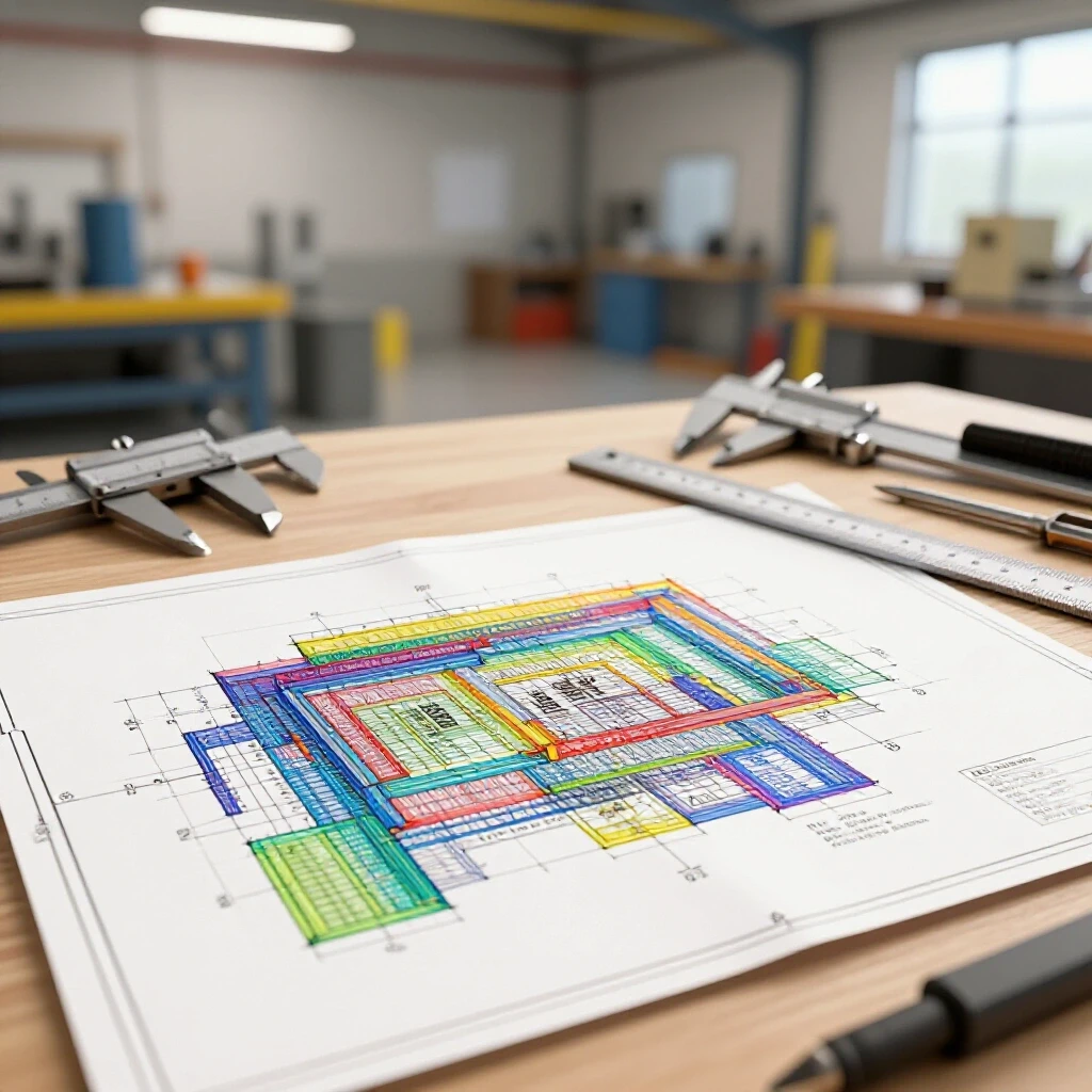
Baseline dimensioning is a layout strategy where every measurement is taken from a single, fixed starting point called a datum. This prevents the error of one measurement from being carried over into the next one.
Most beginners use “chain dimensioning,” where they measure from point A to B, then from B to C. If you are off by just 1/32 of an inch on your first mark, and another 1/32 on your second, by the time you reach the end of a long frame, you could be off by a half-inch or more. This is what we call “tolerance stack-up.” By always pulling your tape measure from the same corner (the datum), you ensure that a small mistake on one hole doesn’t move every other hole down the line.
Establishing a Reliable Datum Point
A datum point is a reference surface or edge that you trust to be straight and true. It is the “zero” for your entire project.
In my shop, I always start by identifying the cleanest, straightest edge of my material. I mark this with a “D” for datum. Every single measurement for the rest of the build starts from that edge. If I am building a four-sided frame, I pick one corner as my master reference. This simple habit has saved me more time and wasted material than any expensive tool ever could.
Eliminating Creeping Errors in Layout
- Use a scribe, not a pencil: A standard pencil line can be 1/16 of an inch wide. A carbide-tipped scribe creates a line that is only a few thousandths of an inch wide, giving you a much more precise target for your saw or drill.
- Measure twice, mark once, verify thrice: After marking your points from the datum, use a second measuring tool to verify the distance between the marks themselves to catch any math errors.
- Account for the kerf: The “kerf” is the width of the material removed by the saw blade. If you don’t account for the 1/8 inch the blade eats, your parts will always come out short.
Verifying Tool Accuracy Through Calibration
Calibration is the process of checking your measuring tools against a known standard to ensure they are providing accurate readings. Even high-quality manual tools can become knocked out of alignment through daily use or accidental drops.
I once spent an entire morning wondering why my joints weren’t closing up tight. It turned out my primary combination square had been dropped, and the head was sitting at 89.5 degrees instead of 90. That half-degree difference across a two-foot span created a gap that was impossible to weld cleanly. Now, I check my squares every Monday morning before I start any major layout work.
The “Flip Test” for Squares
The flip test is a simple way to check if a square is truly 90 degrees without needing specialized equipment.
To do this, hold your square against a known straight edge (like the factory edge of a cold-rolled steel plate). Draw a line. Then, flip the square over so it faces the opposite direction and align it with the bottom of your line. If the square doesn’t perfectly match the line you just drew, your tool is out of alignment. If there is a gap at the top or bottom, the error is doubled, making it easy to see even with the naked eye.
Checking Calipers and Tape Measures
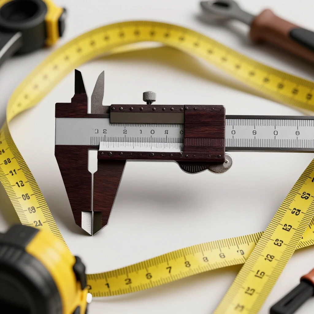
Tape measures are notorious for having a loose “hook” at the end. Many people think this is a defect, but it is actually designed to move by the thickness of the hook itself to account for inside and outside measurements. However, if the hook gets bent or the rivets loosen too much, your accuracy goes out the window.
- Check the Hook: Periodically measure a known 12-inch block. If the tape reads 12-1/16, the hook is likely bent.
- Caliper Zeroing: Before using dial or vernier calipers, ensure the jaws are perfectly clean. Close them completely and ensure they read exactly zero.
- Standardized Tools: If you are working with a partner, ensure you are both using the same brand and model of tape measure. Believe it or not, different brands can have slight variations over long distances.
Managing Heat Distortion and Structural Integrity
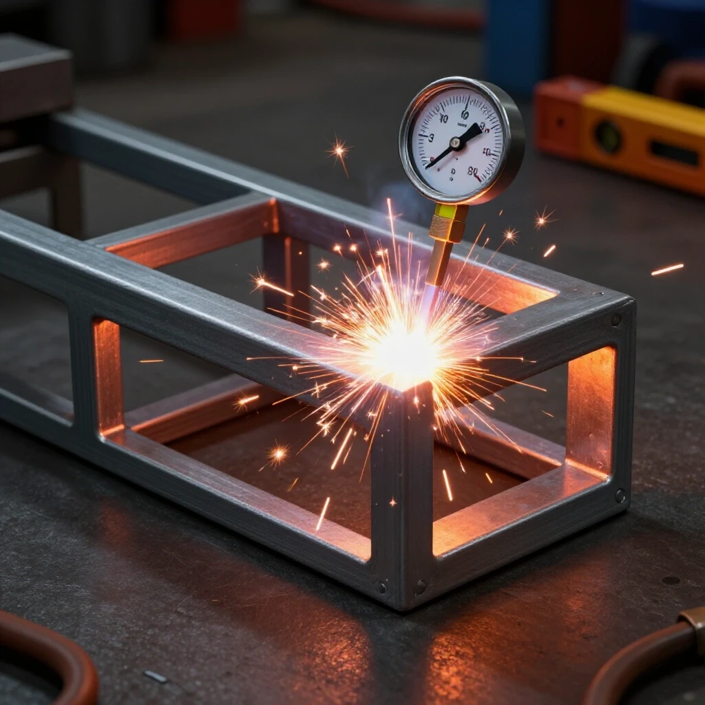
Heat distortion occurs when the intense heat of welding causes the metal to expand and then contract as it cools, pulling the project out of alignment. This is often the biggest cause of “measurement error” that has nothing to do with the ruler.
In the welding world, we talk about the Heat-Affected Zone (HAZ). This is the area of metal around the weld that didn’t melt but reached high enough temperatures to change its physical properties. The HAZ is often where structural failures begin because the metal can become more brittle or lose its original strength. If you don’t manage your heat, the shrinking metal can pull a perfectly measured frame out of square by a significant margin.
Common Weld Defects and Accuracy Issues
| Defect Name | Physical Cause | Impact on Accuracy | Prevention Strategy |
|---|---|---|---|
| Undercut | Too much heat/wrong angle | Weakens joint edge | Reduce amperage; check travel speed |
| Warping | Excessive heat input | Pulls parts out of square | Use skip welding; tack heavily |
| Porosity | Poor gas coverage | Internal structural voids | Set gas flow to 15-20 CFH |
| Lack of Fusion | Surface contamination | Joint fails under load | Proper grinding and cleaning |
Strategies for Minimizing Thermal Pull
- Tack Welding: Use small, strong tack welds at all corners before doing any final welding. This holds the structure in place and resists the pulling forces of the cooling metal.
- Skip Welding: Instead of welding one long bead, weld a small section on one side, move to the opposite side of the project, and weld there. This distributes the heat more evenly.
- Clamping and Fixturing: Use heavy C-clamps or a dedicated welding table to physically restrain the parts. Leave the clamps on until the metal is cool to the touch.
Safety Protocols for the Precision Workshop
Workshop safety is not just about wearing goggles; it is about creating an environment where you can work accurately without distraction or danger. A cluttered shop leads to tripped feet and dropped tools, both of which ruin your precision and your health.
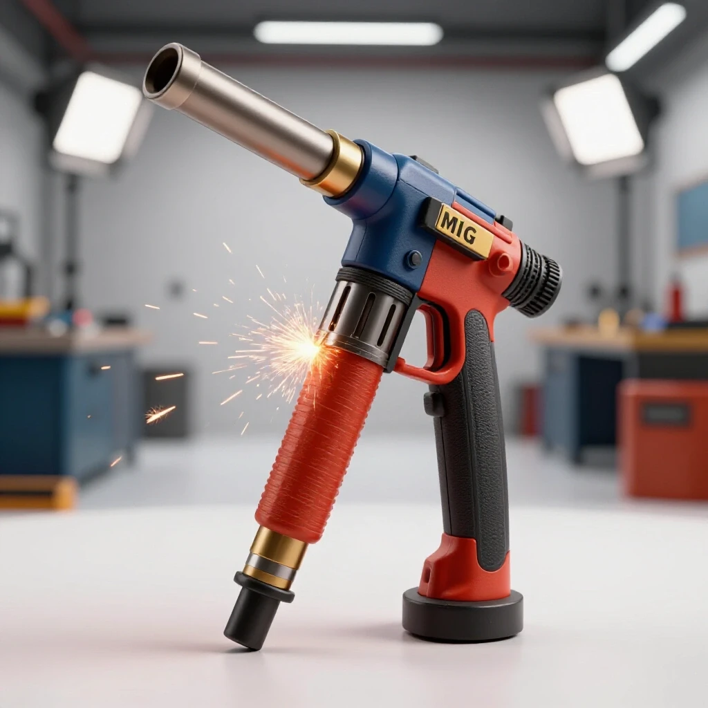
When I am welding, I follow a strict protocol. I ensure my shielding gas flow rate is set between 15 and 20 CFH (cubic feet per hour) for MIG welding. If the flow is too low, I get porosity (tiny bubbles) in my weld, which ruins the structural strength. If it’s too high, it creates turbulence that sucks in oxygen, causing the same problem. Safety and quality are two sides of the same coin.
Essential PPE and Environmental Safety
Your eyes and lungs are your most important tools. You cannot measure accurately if you are squinting through a damaged lens or coughing from fumes.
- Welding Helmet: Use a modern auto-darkening helmet with a Shade 10 to 13 rating depending on your amperage. This protects against “arc eye,” which feels like having sand in your eyes.
- Ventilation: Ensure you have a fume extractor or at least a high-volume fan moving air away from your face. Welding galvanized steel or painted metal can release toxic vapors.
- Fire Safety: Keep a fire extinguisher (Class ABC) within arm’s reach. Always clear the floor of sawdust or oily rags before striking an arc.
Recommended PPE for Safe Fabrication
| Equipment | Rating/Standard | Purpose |
|---|---|---|
| Auto-Darkening Helmet | Shade 10-13 | Protects eyes from UV/IR radiation |
| Welding Gloves | Top-grain leather | Protects against burns and sharp edges |
| Respirator | P100 Filter | Filters out metallic dust and fumes |
| Safety Glasses | ANSI Z87.1 | Protects from flying slag and grinding sparks |
Sequential Verification and Final Inspection
Sequential verification is the habit of checking your work at every stage of the build—after the layout, after the tack welds, and after the final beads are laid.
I use a simple checklist for every joint I weld. If I miss a step, I don’t move forward. This “stop-gate” mentality prevents a small error at the beginning from becoming a disaster at the end. For example, if I find that a frame has pulled 1/8 inch out of square after tacking, it is easy to break a tack and fix it. If I wait until the whole thing is welded, I have to reach for the abrasive saw and start over.
The Structural Verification Checklist
- Pre-Weld Alignment: Are all parts sitting on the datum marks? Is the joint gap consistent (usually 1/16″ to 1/8″ for penetration)?
- Tack Check: After tacking, is the frame still square? Check the diagonals. If the diagonal measurements are equal, the frame is square.
- Weld Profile: Is the weld bead slightly convex (bulging out)? A concave (sunken) weld often lacks the necessary throat thickness to hold a load.
- Post-Weld Cooling: Did the structure move during cooling? Re-measure the critical dimensions before removing the clamps.
Conclusion: Building a Culture of Precision
Eliminating cumulative errors is not about being a perfectionist; it is about being a responsible builder. When you take the time to calibrate your squares, establish a datum, and manage your heat, you are ensuring that your project will perform safely for years to come.
I have seen the consequences of “good enough” measurements. They range from wobbly tables to collapsed equipment trailers. By treating every measurement as a critical data point, you protect your time, your money, and most importantly, the people who will use what you build. Start small: check your square today, and use a scribe on your next project. You will notice the difference in the fit and finish almost immediately.
Frequently Asked Questions
How do I know which end of the metal to use as my datum?
Choose the edge that is the longest and appears the straightest from the factory. If all edges are rough, you may need to grind or file one edge straight using a known straightedge as a guide. Once that edge is true, mark it clearly so you don’t lose track of it.
Why are my diagonal measurements different even if my sides are the same length?
If the opposite sides of a rectangle are equal but the diagonals are different, you have a parallelogram, not a rectangle. This happens because the corners are not at 90 degrees. You must adjust the frame until the diagonals are identical to ensure it is perfectly square.
Can I use a regular tape measure for high-precision work?
For most general fabrication, a high-quality tape measure is sufficient if used correctly. However, for parts that must fit with less than 1/32-inch tolerance, you should switch to a steel rule or calipers. Always use the “inch-on” method—starting your measurement at the 1-inch mark instead of the hook—to eliminate hook play.
What is the best way to correct a frame that has warped?
If a frame has warped slightly, you can sometimes “counter-bend” it using clamps or use a torch to apply heat to the opposite side of the weld, which will pull it back as it cools. However, it is always better to prevent warping through proper tacking and heat management.
How often should I calibrate my manual measuring tools?
In a hobbyist shop, checking your tools once a month is usually enough. However, if you drop a square or a pair of calipers, check them immediately. It only takes a second for a tool to lose its accuracy after a fall onto a concrete floor.
Why does the “kerf” matter so much in layout?
The kerf is the thickness of the material turned into dust by your saw blade. If you mark a piece at 12 inches and cut exactly on the line, your piece will be 11-15/16 inches long because the blade ate 1/16 of an inch of your “good” material. Always cut on the “waste” side of your scribe line.
What is the most common cause of joint failure in home fabrication?
Poor fit-up is the primary culprit. When there are large, uneven gaps between parts because of poor measuring, the welder often tries to “bridge” the gap with extra weld metal. This often results in lack of fusion or excessive internal stress, leading to a crack under load.
How do I ensure my shielding gas is working correctly?
Check your regulator and listen for a gentle “hiss” at the torch when you trigger it. Look at your welds; if you see tiny holes that look like a sponge, you have porosity. This means your gas flow is either too low, blocked by a clogged nozzle, or being blown away by a breeze in the shop.
(This article was written by one of our staff writers, James Harlan. Visit our Meet the Team page to learn more about the author and their expertise.)