How to Inspect Raw Steel Stock for Rust and Warp (Checklist)
I have spent nearly two decades standing over vibrating lathes and shielding my eyes from the erratic arc of a contaminated weld. In my eighteen years as a millwright and diagnostic specialist, I have learned that the most complex mechanical failures often have the simplest, most overlooked origins. We often blame a motor controller or a dull carbide insert when a part comes off the machine out of spec, but the reality is frequently hidden in the raw material itself. If the foundation of your project—the raw steel—is compromised by oxidation or structural distortion, every subsequent step in your workflow will be an uphill battle against physics.
Why Surface Integrity and Straightness Dictate Fabrication Success
Evaluating the initial state of your metal stock is the first step in any metalworking diagnostic guide because it eliminates variables before they enter your machine. If you skip this, you might spend hours troubleshooting weld porosity or adjusting a lathe alignment that wasn’t actually broken.
Steel that enters your shop is rarely perfect, and assuming it is can lead to a cascade of technical frustrations. Surface oxidation acts as a barrier to electrical conductivity and chemical purity, while internal stresses or physical bends manifest as tool chatter and alignment errors. By developing a systematic habit of checking your materials upon arrival, you protect your equipment from unnecessary wear and ensure that your final tolerances are achievable rather than aspirational.
Identifying Surface Oxidation and Its Impact on Weld Quality
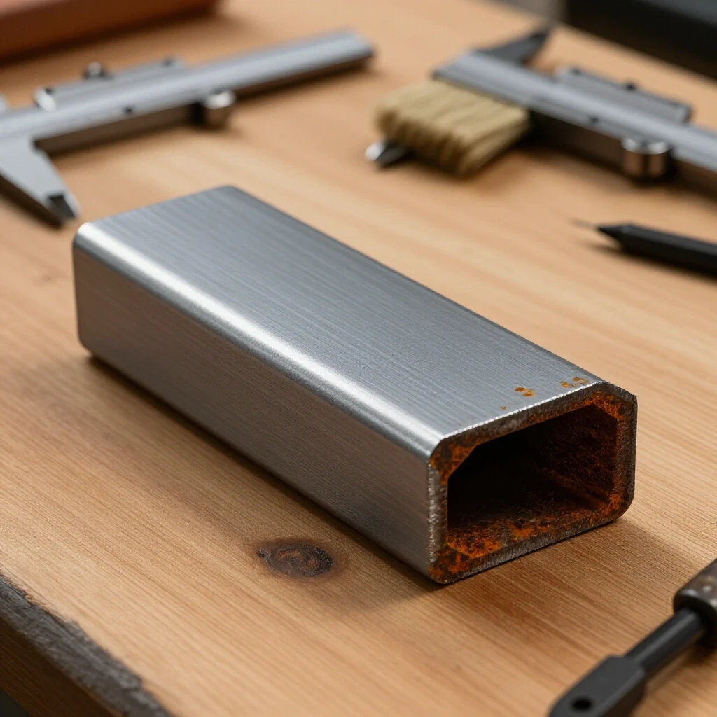
Surface oxidation, commonly known as rust, is a chemical reaction where iron reacts with oxygen and moisture to create iron oxide. In a fabrication environment, this layer introduces hydrogen and oxygen into the weld pool, which is a primary driver of troubleshooting weld porosity and structural cracking.
When I am called to a shop to diagnose poor weld penetration or “popping” during a MIG sequence, the first thing I do is run a finger across the raw stock. If I feel a gritty texture or see a reddish-brown film, I know the shielding gas isn’t the problem; the material is. Rust is porous and holds moisture. When the heat of the arc hits that moisture, it turns into hydrogen gas, which gets trapped in the cooling metal. This creates a “Swiss cheese” effect inside your joint that no amount of voltage adjustment can fix.
- Flash Rust: This is a thin, uniform layer of orange or red dust. It usually wipes off with a rag but indicates the steel has been exposed to high humidity.
- Scale (Mill Scale): A bluish-black, flaky layer formed during the hot-rolling process. While not “rust” in the traditional sense, it is an insulator that causes arc instability.
- Pitting: This is the most severe form of oxidation. It represents localized deep holes where the metal has been eaten away. Pitted steel is often unusable for high-precision machining because the structural integrity is compromised.
| Oxidation Type | Visual Indicator | Impact on Fabrication | Diagnostic Priority |
|---|---|---|---|
| Flash Rust | Light orange dust | Causes minor porosity; clogs sanders | Low – Cleanable |
| Mill Scale | Dark blue/grey flakes | Arc wander; poor paint adhesion | Moderate – Must grind |
| Deep Pitting | Dark craters/holes | Structural weakness; tool snagging | High – Reject stock |
Detecting Mechanical Warpage and Longitudinal Twist
Mechanical warpage refers to a deviation from a perfectly flat or straight plane along the length or width of a steel section. These structural deviations are the root cause of tool chatter solutions being ineffective, as a bowed workpiece will vibrate at its own resonant frequency regardless of how tight you clamp the chuck.
I remember a project where a fabricator was losing his mind trying to figure out why his CNC plasma table was “diving” into the plate. He had replaced the torch height controller and checked all his ground leads. I walked over with a six-foot machinist’s straight edge and laid it across his 1/4-inch plate. The center of the plate had a 3/16-inch “oil-can” bow. The machine was fine; the steel was simply shaped like a shallow bowl. Identifying these bends before you start your layout saves hours of recalibration and wasted consumables.
- Bowing: A curve along the flat face of the material.
- Camber: A curve along the edge of the material (often seen in long flat bars).
- Twisting: A corkscrew-like rotation where the two ends of the stock are not in the same plane.
Tools for Verifying Material Rectitude
To perform a professional metalworking diagnostic guide assessment, you do not need expensive laboratory sensors. You need a set of calibrated reference tools that allow you to compare the “real” shape of the steel against a “theoretical” flat plane.
- Machinist’s Straight Edge: A precision-ground steel bar, usually 24 to 72 inches long.
- Feeler Gauges: A set of thin metal strips used to measure the exact gap between the straight edge and the steel surface.
- Precision Square: Used to check if the ends of the stock are cut perpendicular to the long axis.
- Digital Dial Indicator: Essential for checking the “runout” or wobble of round stock when rotated.
- Optical Sighting: Using your eye to look down the length of the steel from one end to the other to spot large-scale twists.
Systematic Troubleshooting Steps for Incoming Steel
A structured approach ensures that you don’t miss subtle defects that could ruin a high-tolerance build. I follow a specific sequence every time a delivery truck backs into the bay, moving from the most obvious visual flaws to the minute dimensional errors.
Step 1: Visual Surface Scanning
Start by looking for “hot spots” of corrosion. If one area of a bundle is heavily rusted while the rest is clean, it suggests localized water damage or chemical exposure. This is a red flag for potential metallurgical inconsistency. Check for “witness marks” from the mill, such as heavy gouges or indentations from transport chains, which can lead to stress risers and cracking during bending or welding.
Step 2: The Straight Edge Test
Lay your straight edge across the width and along the length of the stock. If you can see light under the straight edge, the material is warped. Use your feeler gauges to quantify the gap. For most structural work, a deviation of more than 0.015 inches per foot is cause for concern. If you are doing precision machining, you likely need the stock to be within 0.005 inches across the entire work area.
Step 3: Checking for Longitudinal Twist
Twist is the silent killer of lathe alignment. To check this on square or rectangular tubing, place the material on a known flat surface, like a heavy welding table or a surface plate. If one corner “rocks” when you press down on it, the piece is twisted. You can measure this by placing a digital level on one end of the bar and then moving it to the other end. If the angle changes by more than 0.5 degrees, you will struggle with fit-up and alignment throughout the build.
How Material Defects Trigger Machinery Failures
Understanding the “why” behind material inspection helps you connect the dots between a rusty bar and a broken tool. When steel is not straight or clean, it forces your machinery to work outside of its designed parameters, leading to intermittent and frustrating errors.
Why Warped Steel Causes Tool Chatter
Tool chatter is a resonant vibration that occurs when the cutting tool and the workpiece are not perfectly rigid. If you load a bowed piece of bar stock into a lathe, the center of gravity of that bar is not on the spindle axis. As it spins, it creates a centrifugal force that pulls the bar outward, causing it to whip. This whipping motion creates the characteristic “chatter” marks on the surface. No amount of “tool chatter solutions” like changing speeds or feeds will fix a bar that is physically bent.
Why Rust Ruins Electrical Consistency
In modern welding, the stability of the arc depends on a clean electrical path. Rust and mill scale are non-conductive. When your welding wire hits a patch of rust, the resistance (measured in Ohms) spikes. This causes the voltage to drop and the current to fluctuate. The result is “arc blow,” where the arc wanders uncontrollably, leading to poor fusion and those dreaded “electrical gremlins” that look like machine malfunctions but are actually just poor surface contact.
Troubleshooting Table: Material Defect vs. Machine Symptom
| Material Issue | Observed Machine Symptom | Root Cause |
|---|---|---|
| Bowed Plate | Plasma torch “diving” or “crashing” | Incorrect distance from sensor to metal |
| Heavy Mill Scale | Erratic arc; “cold” welds | High electrical resistance at the surface |
| Longitudinal Twist | Parts won’t square up during assembly | Cumulative error in the material plane |
| Flash Rust | Pinholes in the weld bead | Hydrogen contamination from moisture |
| Deep Pitting | Sudden tool breakage or “snagging” | Interrupted cut and material voids |
Actionable Benchmarks for Acceptable Steel
When you are performing mechanical troubleshooting steps, you need hard numbers to decide whether to keep the steel or send it back to the supplier. Based on standard machinery maintenance literature, here are the tolerances I use in my shop:
- Flatness (Plate): No more than 1/8 inch deviation over a 4-foot span for general fabrication.
- Straightness (Bar/Tube): No more than 1/32 inch per 5 feet of length.
- Surface Condition: No pitting deeper than 0.005 inches if the surface is to be machined.
- Squareness: Ends must be within 0.5 degrees of perpendicular to ensure proper alignment in jigs.
A Case Study in “Phantom” Vibration
I once worked with a shop that was convinced their 10-foot shear was broken. Every time they cut a strip of 10-gauge stainless, the machine would shudder, and the cut would come out jagged. They had already spent three days adjusting the blade gap and checking the hydraulic pressure.
When I arrived, I didn’t look at the shear. I looked at the stack of sheets. I noticed that the sheets were slightly “wavy” along the edges—a common result of improper cooling at the mill. When the shear clamped down on the wavy material, the sheet would flatten out, but the internal tension would cause it to “snap” back during the cut. This was creating a vibration that mimicked a loose blade. We switched to a different batch of flatter material, and the “machine error” vanished instantly. This is why a metalworking diagnostic guide must always start with the raw stock.
Checklist for Pre-Fabrication Material Audit
Before you strike an arc or turn on a spindle, run through this numbered list to ensure your material isn’t going to fight you.
- Wipe Down: Clean the surface with a dry rag to reveal hidden pits or cracks.
- Sight the Length: Look down the edges like a rifle scope to spot obvious bows.
- Straight Edge Check: Check at least three points (both ends and the middle) for flatness.
- Square the Ends: Use a precision square to see if the factory cut is actually 90 degrees.
- Measure Thickness: Use calipers to check at least four corners. Variations in thickness (more than 0.003 inches) can cause uneven heating during welding.
- Verify Grade Marks: Ensure the heat number or grade stamp matches your order; “mystery metal” is a leading cause of metallurgical cracking.
Mastering the Art of Material Diagnostics
Troubleshooting is as much about what you don’t do as what you do. By eliminating the material as a variable, you narrow the field of potential problems significantly. If the steel is clean, straight, and true, then any remaining issues—like tool chatter or weld porosity—are almost certainly related to your machine settings or technique.
Mastering these systematic diagnostic methodologies requires patience. It is tempting to just grab a bar and start cutting, but the thirty seconds you spend with a straight edge can save you three hours of rework. In my experience, the best fabricators aren’t the ones with the most expensive machines; they are the ones who refuse to put bad material into the machines they have.
Frequently Asked Questions
How can I tell the difference between mill scale and heavy rust? Mill scale is usually a dark, slate-grey or bluish color and is very hard. It often looks like part of the metal. Rust is typically orange, red, or brown and is much softer and more powdery. If you can scratch it off with a fingernail, it is likely rust.
Is it possible to fix a bowed piece of steel, or should I return it? Small bows can often be “pulled out” during the welding process by using specific heat-shrinking techniques or heavy clamping. However, for precision machining, a bowed bar should be returned or used for less critical parts, as the internal stresses will cause the part to move as you remove material.
Can I weld over light flash rust if I turn up the heat? I strongly advise against this. While “turning up the heat” might burn through some of the oxidation, the moisture trapped in the rust will still release hydrogen into the weld pool. This leads to troubleshooting weld porosity issues that can weaken the joint. Always clean the weld zone to bright metal.
Why does my lathe vibrate even when the bar looks straight? Even if a bar looks straight to the eye, it may have an internal “twist” or be “out-of-round.” Use a digital dial indicator to check the runout. A deviation of just 0.002 inches can be enough to cause significant vibration at high RPMs.
What is the best way to measure a twist in a long square tube? Place the tube on a flat surface and use a digital protractor or a machinist’s level. Check the level at one end, then slide it to the other end without rotating the tube. Any change in the degree reading indicates a twist over that length.
Does rust on the surface affect the internal strength of the steel? Surface rust (flash rust or scale) generally does not affect internal strength. However, deep pitting is a different story. Pitting acts as a “stress riser,” which is a point where a crack is likely to start when the metal is under load.
How does “oil-canning” affect CNC plasma cutting? “Oil-canning” is when a flat sheet has a bulge that can pop back and forth. This makes it impossible for a fixed-height torch to maintain a consistent gap. Even with a Torch Height Controller (THC), the rapid movement of the metal can cause the sensor to overcompensate, leading to poor cut quality.
Can warped material cause a drill bit to wander? Yes. If the surface of the metal is not perpendicular to the drill bit, the tip of the bit will try to follow the slope of the warp rather than biting straight in. This is why center punching and ensuring material flatness are critical for hole alignment.
Is mill scale conductive enough for a ground clamp? Not reliably. Mill scale can act as an insulator. Always grind a small “bright spot” for your ground clamp to ensure a consistent electrical path and to avoid overheating your ground lead.
What is the most common mistake when inspecting raw stock? The most common mistake is only checking one side of the material. Steel can be perfectly flat on one face but have a significant bow or “crown” on the other due to how it was rolled. Always inspect all functional surfaces.
(This article was written by one of our staff writers, Paul Whitaker. Visit our Meet the Team page to learn more about the author and their expertise.)