How to Transfer Dimensions Safely from Paper to Steel (Tips)
I have spent 14 years on the shop floor, and if there is one thing I have learned, it is that a project’s success is decided long before a torch is lit. In my early years as a mechanical engineer and fabricator, I once misread a blueprint for a heavy-duty equipment rack. I transferred a hole center-point just three millimeters off the mark. When the final assembly was loaded, the off-center bolt created a leverage point that the steel was never designed to handle. The resulting structural failure was a loud, expensive reminder that precision in the layout phase is a safety requirement, not just a matter of pride.
When we move dimensions from a paper drawing to a piece of steel, we are translating a theory into a physical reality. For intermediate fabricators, this is where the most common errors occur. A small slip of a ruler or a thick pencil line can lead to parts that do not fit, or worse, structures that harbor hidden stresses. My goal is to help you manage these risks by using proven manual layout techniques that ensure your projects are built on a foundation of accuracy.
The Importance of Establishing a Reliable Datum
A datum is a fixed starting point or a reference surface from which all other measurements are taken. In manual layout, using a consistent datum prevents “stacking errors,” which happen when you measure from one mark to the next, causing small mistakes to add up over the length of the steel.
In my inspection work, I often see frames that are out of square because the builder measured from different edges for each hole. To avoid this, you must select one factory edge or a machined surface as your primary datum. This ensures that even if one measurement is slightly off, it does not push every subsequent mark further out of alignment. This practice is vital for maintaining the structural metal load capacity, as it ensures that weight is distributed exactly where the designer intended.
- Always mark your datum edge with a “D” or a specific symbol so you do not forget which side is your baseline.
- Use a combination square to verify that your datum edge is actually straight before you start.
- Measure every feature from that single edge rather than measuring “point-to-point.”
Essential Manual Tools for Layout Precision
High-quality manual tools are the primary defense against fabrication errors. Steel rules, spring dividers, and squares allow you to move dimensions with a level of accuracy that a standard tape measure cannot provide. These tools are designed to sit flat against the metal, reducing the distance between the scale and the surface.
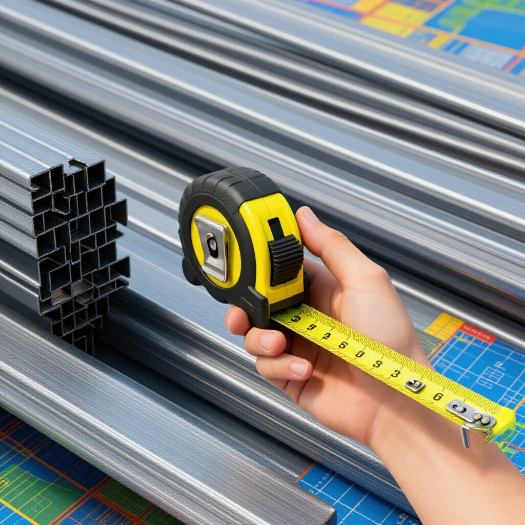
When I talk about accuracy, I am referring to the ability to repeat a measurement within a very tight tolerance. For structural work, a tolerance of +/- 0.5mm is often the goal. Using a flexible tape measure for this is risky because the hook at the end can move, and the thickness of the tape creates a gap that leads to visual errors. A rigid steel rule eliminates these variables.
| Tool Name | Primary Purpose | Accuracy Level | Common Failure Mode |
|---|---|---|---|
| Steel Rule | Linear measurements | High (0.5mm) | Parallax error from poor viewing angle |
| Combination Square | 90 and 45-degree angles | High | Loose locking nut causing blade shift |
| Spring Dividers | Scribing arcs and circles | Very High | Tips becoming dull or bent |
| Scrying Awl/Scribe | Marking fine lines | High | Following the grain of the metal |
| Center Punch | Creating a physical “seat” | Moderate | Hammer strike shifting the point |
Managing Parallax and Visual Errors in Layout
Parallax error occurs when your eye is not positioned directly over the measurement scale, causing the mark to appear shifted to one side. This is a common cause of structural design uncertainty, as even a small visual shift can lead to a hole being drilled in the wrong location.
To combat this, I always teach new fabricators to look “dead-on” at the rule. If you are looking from an angle, you might be off by the thickness of the rule itself. In my shop, I use a magnifying glass for critical marks to ensure the scribe tip is exactly in the center of the graduation line. This level of care reduces the risk of creating a heat affected zone weakness later in the process by ensuring all joints and holes are perfectly aligned with the load paths.
- Place the steel rule on its edge so the graduations touch the metal surface.
- Use high-intensity, directional lighting to eliminate shadows that hide your marks.
- Double-check the dimension from both directions to confirm the center point.
Scribing and Punching for Permanent Accuracy
A scribe is a hardened steel tool used to scratch a fine line into the surface of the metal. Unlike a marker or a pencil, a scribe line has no width, which means it provides a much more precise target for your tools. Once the line is set, a center punch is used to create a small indentation.
This indentation is critical because it prevents your drill bit or other tools from wandering. However, you must be careful with the depth of your punch. In high-stress areas, a very deep punch can act as a stress riser—a point where cracks can begin to form under heavy loads. I use a “prick punch” with a 60-degree point for the initial mark and a “center punch” with a 90-degree point to widen it only once I am sure the location is correct.
- Use layout fluid (bluing) to make your scribe lines stand out clearly against the steel.
- Hold the scribe at a consistent angle to ensure the line is as close to the rule as possible.
- Tap the punch lightly first, inspect the location, then strike it firmly once confirmed.
Understanding Material Stress and Layout Marks
Every mark you make on a piece of steel changes its surface. While a scribe line seems small, it is technically a microscopic notch. In the world of mechanical engineering, we call these “stress concentrators.” If a scribe line is placed perpendicular to the direction of a heavy load, it can become the starting point for a brittle fracture.
During my years of inspecting industrial components, I have seen structural failures that started at a simple layout mark. To keep your projects safe, avoid scribing deeply in areas that will experience high tension. If you are working with high-carbon steels or thin-walled tubing, consider using a soft layout pencil for non-critical marks to maintain the material’s integrity.
- Avoid “over-scribing” lines past the point where they are needed.
- Use a light touch on structural members that will be under constant vibration.
- Understand that the yield strength of the metal can be slightly affected by surface damage.
Workshop Safety and Ergonomics During Layout
Layout work requires focus, and focus is hard to maintain if you are uncomfortable or in an unsafe environment. Garage fabrication safety starts with a clean, well-lit workbench. If you are leaning over a cluttered table to reach a piece of steel, you are more likely to make a mistake or strain your back.
Safety also involves the tools themselves. Scribes and dividers are incredibly sharp. I have seen many “near-miss” incidents where a fabricator reached across a table and caught their arm on a divider tip. Always store these tools in a protective case or with the points retracted when not in use. Additionally, when striking a punch with a hammer, always wear safety glasses to protect against small metal chips that can fly off the hardened steel.
- Clear the Workspace: Remove all unnecessary tools and scrap metal from your layout area.
- Level the Work: Ensure your steel is supported flat so it does not shift while you are measuring.
- Check Your Lighting: Shadows are the enemy of accuracy; use a movable lamp to light the specific area you are marking.
- PPE Integration: Wear thin, cut-resistant gloves that allow for dexterity while protecting your hands from sharp steel edges.
Verification: The “Measure Twice, Cut Once” Framework
Before you move from the layout phase to the next step, you must perform a final verification. I use a formal checklist to ensure that my physical marks match the paper drawing. This is the last chance to catch a mistake before it becomes a permanent part of the structure.
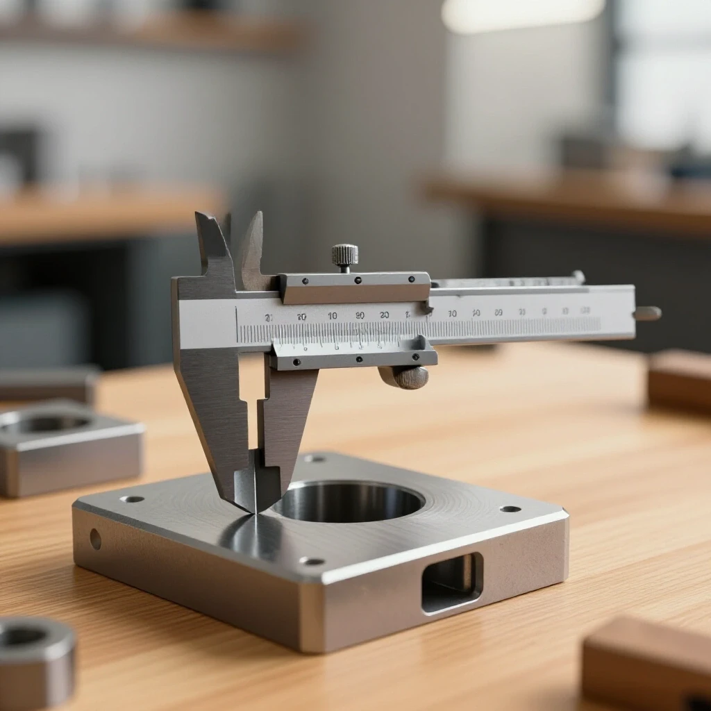
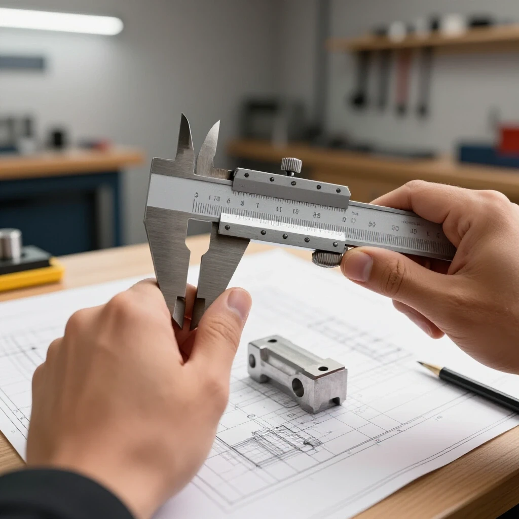
I recommend using a different tool for the verification than the one you used for the initial layout. If you used a steel rule to set the marks, use a set of calipers to check them. This prevents you from repeating the same visual error twice. In my 14 years of fabrication, this “second-tool check” has saved more projects from the scrap bin than any other technique.
- Check 1: Verify the datum edge is still the reference point for all marks.
- Check 2: Re-read the blueprint to ensure no dimensions were transposed (e.g., 69mm vs. 96mm).
- Check 3: Measure the “overall” length to ensure the sum of the parts equals the whole.
- Check 4: Check for squareness using the 3-4-5 triangle method for large frames.
Common Layout Mistakes and How to Avoid Them
Even experienced fabricators make mistakes. The key is to recognize the patterns that lead to these errors. One common issue is neglecting the “thickness of the line.” If you use a thick marker, the line itself could be 1mm wide. If you cut to the left of the line on one side and the right on the other, your part could be 2mm off.
Another mistake is failing to account for the physical limits of the material. Steel expands and contracts with temperature. If you layout a very long beam in a freezing garage using dimensions calculated for a warm shop, you might find your marks are slightly off once the metal warms up. While this is rare for small projects, it is a factor in large-scale structural work.
- Mistake: Measuring from a rough, torch-cut edge. Solution: Always grind your datum edge smooth and square first.
- Mistake: Using a bent or damaged rule. Solution: Inspect your layout tools weekly for straightness and clarity.
- Mistake: Forgetting to account for the radius of a bend. Solution: Calculate the “bend allowance” before marking your fold lines.
Actionable Workshop Safety Checklist for Layout
Before you place your first mark, go through this safety and accuracy audit. This process ensures that you are mentally and physically prepared for the precision required.
- Tool Inspection: Are the scribe and punch sharp? Is the square locked tight?
- Material Prep: Is the steel clean of mill scale and oil so the marks will stick?
- Blueprint Review: Do I understand the load paths and where the critical dimensions are?
- Ergonomic Setup: Is the workpiece at a comfortable height to prevent leaning?
- Safety Gear: Are my safety glasses on before I use the hammer and punch?
Conclusion
Transferring dimensions from paper to steel is the most critical step in ensuring a project is safe and structurally sound. By using a consistent datum, high-quality manual tools, and a rigorous verification process, you can eliminate the uncertainty that leads to fabrication failures. Remember that in the workshop, time spent on a precise layout is an investment in safety. A mistake caught with a ruler is a minor inconvenience; a mistake caught after the structure is built can be a disaster. Stay focused, trust your tools, and always respect the physics of the materials you are working with.
FAQ
What is a datum and why is it important in metal layout?
A datum is a specific, reliable starting point—usually a flat edge or a machined surface—from which all measurements are taken. It is important because it prevents “stacking errors.” If you measure from one mark to the next, a tiny error in each measurement will grow larger across the piece. Measuring everything from one datum keeps your errors independent and small.
Why should I use a scribe instead of a permanent marker?
A permanent marker creates a line that has a physical width, sometimes up to 1.5mm. This makes it hard to know exactly where the “true” measurement lies. A scribe scratches a line into the metal that has almost zero width, providing a much more precise target for your square or punch.
How can I prevent parallax error when reading a steel rule?
To prevent parallax error, you must position your eyes directly above the graduation mark you are reading. If you look at the rule from an angle, the mark will appear to be in a different spot than it actually is. Placing the rule on its thin edge so the markings are flush against the steel also helps.
What is the difference between a prick punch and a center punch?
A prick punch has a sharper, 60-degree point and is used for the initial, light marking of a location. It allows for greater precision. A center punch has a blunter, 90-degree point and is used to enlarge the prick punch mark so that a drill bit has a secure place to start without wandering.
How do I ensure my combination square is actually square?
You can check a square by drawing a line perpendicular to a straight edge, then flipping the square over to the other side of the line. If the edge of the square perfectly aligns with the line from both sides, it is square. If there is a gap that widens at the top or bottom, the tool is out of alignment and needs adjustment.
Why does lighting matter so much during the layout process?
Steel is reflective, and scribe lines are very thin. Poor lighting creates shadows and glare that can make a scribe line look like it is in a different position. Directional lighting helps “catch” the edge of the scribe mark, making it glow and ensuring you are placing your tools exactly where they belong.
Can scribing a line on steel cause it to break?
Yes, in specific situations. A scribe line is a “stress riser,” a tiny notch that can concentrate force. In high-tensile structural parts or components subject to heavy vibration, a deep scribe line can act as the starting point for a crack. For these critical areas, use a light touch or a soft pencil.
How do I layout a large circle or arc on a steel plate?
The best way is to use spring dividers. You first use a center punch to create a pivot point in the middle of the circle. Place one leg of the dividers in the punch mark and use the other leg to scribe the arc. This ensures a perfect radius that is consistent all the way around.
What should I do if my steel has a lot of mill scale on it?
Mill scale is a dark, flaky layer on hot-rolled steel that makes it hard to see scribe lines. You should use a wire brush or a light abrasive to clean the area where you will be marking. Applying a layout fluid (bluing) over the cleaned area will make your scribe lines stand out in sharp contrast.
Why is it better to use a steel rule than a tape measure for layout?
Tape measures are designed for construction where tolerances are wider. The sliding hook at the end can become bent or loose, and the “blade” of the tape is curved, which makes it sit away from the metal. A rigid steel rule sits flat, has finer markings, and does not have moving parts that can lose calibration.
(This article was written by one of our staff writers, James Harlan. Visit our Meet the Team page to learn more about the author and their expertise.)