How to Weld a Wind-Resistant Patio Awning Metal Frame (Fix)
I still remember the first time I built a large-scale outdoor frame. I had spent hours measuring, cutting, and cleaning the steel. On the bench, everything looked perfect. The corners were tight, and my square showed a dead-on 90 degrees. But as I finished the final heavy beads on the rafters, I watched in horror as the heat pulled the entire structure three-quarters of an inch out of alignment. By the time the metal cooled, my “square” frame looked more like a trapezoid.
That project was a hard lesson in how metal behaves under thermal stress. I learned that custom fabrication projects are not just about sticking two pieces of metal together. They are about managing the physics of heat. When you are building a heavy-duty exterior shade support, the stakes are high. You aren’t just fighting gravity; you are fighting wind loads that can put hundreds of pounds of pressure on your welds.
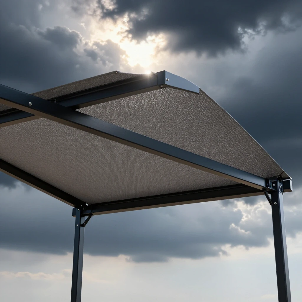
Over my 13 years as a prototype technician, I have found that success comes down to three things: a precise layout, rigid fixturing, and a disciplined weld sequence. If you wing it, the metal will win every time. If you plan for the “pull” of the weld, you can produce a structure that is straight, strong, and capable of withstanding the elements.
Designing a Rigid Outdoor Shade Support
Setting the foundation for a build involves mapping out dimensions, selecting appropriate wall thicknesses, and accounting for the physical forces of wind and gravity before a single cut is made.
When I plan a frame meant to live outdoors, I start with the material. For most residential spans, I prefer 2-inch square structural tubing with a 1/8-inch or 3/16-inch wall thickness. Thinner material might be easier to cut, but it is much harder to weld without warping. Thick walls act as a natural heat sink, absorbing the energy of the arc and resisting the tendency to twist.
I always draw my blueprints to include the “outside-to-outside” dimensions. This is critical because it dictates where your corner joints will sit. If you are building a 10-foot by 12-foot frame, you need to decide if your rafters will sit on top of the headers or flush between them. Flush joints look cleaner, but they require more precise cuts and are more prone to pulling the frame out of square during welding.
- Select 11-gauge (1/8 inch) or 7-gauge (3/16 inch) steel for structural integrity.
- Map out every joint on paper before ordering material.
- Identify where the greatest wind loads will hit; these areas need extra reinforcement.
- Account for the weight of the metal itself to prevent sagging over long spans.
Calculating Kerf Allowances and Accurate Square Cuts
Kerf is the width of the material removed by a cutting tool, and failing to account for it can lead to frames that are consistently short or out of square.
One of the biggest mistakes I see in garage shops is ignoring the kerf. If you use a standard abrasive chop saw, that blade is roughly 1/8 of an inch thick. If you mark your steel at exactly 96 inches and cut on the line, your finished piece will be 95 and 7/8 inches. Over a large frame with multiple joints, those 1/8-inch errors compound. Suddenly, your cross-members don’t fit, or your frame is an inch narrower than planned.
To get accurate square cuts, I use a “stop block” on my saw table. This ensures that every rafter is the exact same length down to the 1/32nd of an inch. If your cuts are even slightly angled, you will have gaps in your joints. Gaps are the enemy of straight welding. When you fill a gap with weld metal, the shrinkage force is much higher, which pulls the frame toward the gap.
| Tool Type | Standard Kerf Width | Tolerance |
|---|---|---|
| Abrasive Chop Saw | 1/8 inch (0.125″) | +/- 1/32″ |
| Cold Saw | 3/32 inch (0.090″) | +/- 0.010″ |
| Horizontal Bandsaw | 0.035 to 0.042 inch | +/- 0.015″ |
| Plasma Cutter | 0.060 to 0.100 inch | +/- 1/16″ |
Constructing Layout Fixtures for Large Scale Frames
Fixtures are temporary structures or clamps used to hold workpieces in the exact position required during the welding process to ensure dimensional accuracy.
You cannot build a straight 10-foot frame in the air. You need a flat surface. If you don’t have a professional 4×8 welding table, the next best thing is a clean concrete garage floor. I use workshop jigs and fixtures to turn my floor into a precision layout tool. I often weld temporary “cleats” (small pieces of scrap angle iron) to my table or bolt them to the floor to create a perimeter.
These cleats act as a hard stop. Once I lay my tubing against them, I know the frame is square. I also use “F-style” clamps and heavy-duty magnets to keep the metal from jumping when I strike the arc. Interestingly, even a heavy piece of steel will move the moment the arc hits it due to localized thermal expansion. Physical restraint is the only way to minimize this movement.
- Use a 3-4-5 triangle (Pythagorean theorem) to check for square over long distances.
- Ensure your layout surface is level to prevent a “propeller” twist in the frame.
- Clamp the material every 24 inches to maintain contact with the fixture.
- Use sacrificial spacers if you need to weld the underside of a joint without flipping the frame.
Why Weld Shrinkage Warps Square Structures
Metal warping solutions begin with understanding that welding is essentially a process of controlled melting and cooling. When you heat steel to its melting point, it expands. As it cools and solidifies, it contracts. However, the weld metal often shrinks more than the surrounding base metal. This creates a “pulling” force.
If you weld only one side of a tube, that side will shrink and “bow” the entire length of the steel. In a square frame, this manifests as the corners pulling inward. This is known as angular distortion. I have seen 2-inch tubing pull five degrees out of square from a single heavy bead. To combat this, you must treat the frame as a living thing that wants to move, and your job is to give it nowhere to go.
- Thermal Expansion: The metal grows as it gets hot.
- Elastic Limit: If the metal is restrained while hot, it can permanently deform.
- Shrinkage Force: As the weld cools, it exerts thousands of pounds of pull.
- Heat Dissipation: Faster cooling often leads to more drastic warping.
The Strategic Sequence of Tack Welding
A tack weld is a small, temporary weld used to hold parts in place before the final beads are applied. In custom fabrication projects, the tacking phase is where the battle for squareness is won or lost. I never lay a full bead until the entire structure is tacked together and verified.
I use a specific tacking pattern. I place one tack on the “inside” corner, then check for square. Then, I place a tack on the “outside” corner. Each tack should be about 1/4 inch long and have good penetration. If you only tack one side, the cooling metal will act like a hinge and pull the joint toward the tack. By placing tacks on opposite sides, you balance the forces.
- Place tacks at the corners first, then in the center of long spans.
- Check your diagonal measurements after every four tacks.
- If the frame moves, cut the tack with a thin zip-disk and reset.
- Keep tacks small enough to be consumed by the final weld but strong enough to resist the pull.
Executing Weld Sequences to Minimize Distortion
Weld sequencing is the specific order in which you place your beads to balance the heat input and counteract the natural pulling forces of cooling metal.
Once the frame is tacked and square, the temptation is to start at one corner and go all the way around. This is a recipe for a warped frame. Instead, I use a “staggered” or “back-stepping” sequence. I might weld the top of Joint A, then move to the opposite corner of the frame and weld the top of Joint D. This allows the heat to dissipate and prevents any one area from getting so hot that it loses its structural rigidity.
Another technique I use is “welding toward the restraint.” I start my beads at the open end of a joint and move toward the part of the frame that is already tacked or clamped. This pushes the expansion into the solid part of the structure rather than letting it push the free end out of alignment.
| Joint Type | Recommended Sequence | Goal |
|---|---|---|
| Corner Joint | Outside edge first, then inside | Prevents the corner from “closing” |
| T-Joint | Alternate sides every 2 inches | Balances the pull on the vertical member |
| Long Butt Weld | Center-out (staggered) | Minimizes longitudinal bowing |
| Rafter to Header | Weld vertical sides first | Maintains height consistency |
Strengthening Joints with Structural Gussets and Bracing
Gussets are triangular plates used to reinforce the corners of a frame, significantly increasing its ability to withstand lateral forces like wind gusts.
For an exterior structure, a simple butt weld is rarely enough. Wind acts as a giant lever against your frame. To make the structure wind-resistant, I add gussets to every primary corner. A 4-inch by 4-inch triangular gusset made of 3/16-inch plate increases the surface area of your weld and creates a much more rigid joint.
When I install gussets, I follow the same metal layout tips as the main frame. I tack them in place on all sides before welding. Interestingly, gussets themselves can cause warping if you weld them too hot. I prefer to weld the “flat” sides of the gusset first, then the corners. This locks the geometry in place before the high-heat corner welds are finished.
- Cut gussets with a 45-degree angle for a clean, professional look.
- Leave a small “snipe” or clipped corner on the gusset to allow it to sit flush against the weld root.
- Use cross-bracing on spans longer than 8 feet to prevent lateral sway.
- Ensure all gussets are identical in size to keep the load distribution even.
Post-Weld Straightening and Alignment Checks
Post-weld alignment involves checking the final dimensions against the plan and using controlled heat or mechanical force to bring the structure back into tolerance.
Even with the best sequencing, some movement is inevitable. Once the frame is cool, I perform a final measurement check. My goal is a dimensional tolerance of +/- 1/16th of an inch. If a rail has bowed, I use a technique called “flame straightening” or “heat shrinking.” By applying heat to the side of the tube opposite the bow, I can force that side to expand and then shrink, pulling the rail back into a straight line.
I also use mechanical leverage. A heavy-duty pipe clamp can often pull a stubborn corner back into square while I add a final reinforcement weld. I document these adjustments in a post-weld alignment log. This helps me track which joints pulled the most, so I can adjust my sequence on the next build.
- Measure diagonals (corner to corner) to verify squareness.
- Use a straightedge to check for “crown” or “bow” in long tubes.
- Apply localized heat to the high side of a curve to shrink it straight.
- Record the final dimensions for future reference and mounting accuracy.
Actionable Framework for Frame Fabrication
To ensure a successful build, I follow a strict checklist. This keeps me from skipping steps when I am tired or rushing to finish a project.
- Phase 1: Preparation
- Clean all mill scale off the steel at the weld zones using a flap disc.
- Double-check the cut list against the raw material on hand.
- Calibrate the chop saw to exactly 90 degrees using a machinist square.
- Phase 2: Layout
- Map the frame on the floor and secure the perimeter cleats.
- Lay out the main headers and rafters.
- Verify the 3-4-5 squareness of the base.
- Phase 3: Tacking
- Place 1/4-inch tacks on the top and bottom of every joint.
- Re-measure diagonals; they must be within 1/8 inch before proceeding.
- Add side tacks to lock the joints.
- Phase 4: Final Welding
- Follow the staggered sequence (Corner 1, Corner 3, Corner 2, Corner 4).
- Monitor heat; if the metal glows dull red for more than a few seconds, stop and let it cool.
- Install gussets and bracing last to lock in the final shape.
Common Fabrication Pitfalls and How to Avoid Them
One of the most frequent mistakes I see is “over-welding.” Builders think that more weld is always better, but excessive heat just leads to more distortion. If a 2-inch bead provides the necessary strength, a 6-inch bead won’t make it stronger; it will just make the frame look like a banana.
Another pitfall is poor fit-up. If your cuts are sloppy and you have a 1/8-inch gap on one side of a joint, that joint will pull toward the gap as the weld cools. I spend 70% of my time on fit-up and layout and only 30% on actual welding. A tight fit-up requires less filler metal, generates less heat, and results in a much straighter finished product.
- Avoid “weaving” wide beads on thin-wall tubing; use a series of stringer beads instead.
- Don’t remove the clamps until the metal is cool to the touch.
- Never weld in a drafty area; uneven cooling can cause the metal to warp unpredictably.
- Clean your nozzle frequently to ensure a stable arc and consistent heat input.
Building a heavy-duty outdoor frame is a rewarding challenge. It forces you to think like an engineer and act like a craftsman. By focusing on the physics of the metal and maintaining a disciplined layout, you can create a structure that stays square and stands up to the wind for years to come.
Frequently Asked Questions
Why did my frame pull 5 degrees out of square even though I clamped it?
Clamping prevents movement during the weld, but the moment you release the clamps, the internal stresses of the cooling metal take over. This is why weld sequencing is vital. You must balance the pull by welding the opposite side of the joint to create an equal and opposite force.
Can I use thin-wall tubing to save weight on a large awning?
I don’t recommend it for wind-resistant structures. Thin-wall tubing (like 16-gauge) warps much faster and has less surface area for the weld. For something that needs to survive high winds, 1/8-inch wall thickness is the practical minimum for structural reliability.
How big should my tack welds be for a 2-inch tube frame?
Aim for tacks that are roughly 1/4 inch long with good “tie-in” to both pieces of metal. If the tacks are too small, the shrinkage force of the first full bead will snap them. If they are too big, they are hard to weld over cleanly.
Do I need to weld all four sides of a square tube joint?
Yes, for an outdoor structure subject to wind, you need a full perimeter weld. This not only provides maximum strength but also seals the inside of the tube from moisture, preventing internal rust that can weaken the frame over time.
What is the best way to check for square on a 12-foot span?
Measure the diagonals. Measure from the far left corner to the far right corner, then vice versa. If the two measurements are identical (within 1/16th of an inch), your frame is square. This is much more accurate than using a small handheld square.
How do I fix a bow in a long rail after I’ve finished welding?
You can use “heat shrinking.” Heat a small spot on the “outside” of the bow with an oxy-acetylene torch until it is cherry red, then quench it with a wet rag. The rapid contraction will pull the metal back toward the heat, straightening the rail.
Should I use MIG or TIG for this type of frame?
MIG is generally better for large outdoor frames because it is faster and handles gaps better. TIG provides beautiful welds but puts a lot of heat into the metal over a longer period, which can actually increase the risk of warping on large structures.
How does wind affect the joint design?
Wind creates “moment” or twisting forces. A simple butt joint can fail under repeated stress. Adding gussets or “fish plates” over the joints distributes that stress over a larger area, preventing the weld from cracking under the constant vibration of the wind.
What is a “heat sink” and do I need one?
A heat sink is a heavy piece of metal (usually copper or aluminum) placed behind or near the weld to soak up excess heat. While not always necessary for 1/8-inch steel, using a heavy steel table as a heat sink helps keep the temperature down and reduces warping.
How do I prevent the legs of the frame from splaying outward?
Weld a temporary “spreader bar” near the bottom of the legs before you weld the top joints. This bar holds the legs at the exact distance required. Once the top welds are cool and the gussets are in place, you can cut the spreader bar off.
What is the 3-4-5 rule for layout?
It is a way to ensure a perfect 90-degree angle. Mark 3 feet on one rail and 4 feet on the perpendicular rail. If the distance between those two marks is exactly 5 feet, the corner is perfectly square. For larger frames, you can use 6-8-10.
How much gap is acceptable in a joint before welding?
Ideally, you want a “zero-gap” fit-up for the best control. However, a gap of up to 1/32 of an inch is manageable. If the gap is larger than 1/16, the weld will pull significantly more, and you should consider re-cutting the piece for a tighter fit.
(This article was written by one of our staff writers, Robert Kline. Visit our Meet the Team page to learn more about the author and their expertise.)