How to Build an Adjustable Welding Positioner Stand (Plan)
I remember the first time I tried to build a heavy-duty bumper for my truck. I spent three hours measuring, scribing lines, and triple-checking my angles. Everything looked perfect until I laid down the final beads. As the steel cooled, I watched in frustration as the ends of the bumper pulled forward by nearly half an inch. My “perfect” layout had been defeated by the physics of heat. That day, I learned that custom fabrication projects are as much about managing thermal forces as they are about sticking metal together.
In my thirteen years as a prototype technician, I have realized that the most valuable tool in any shop isn’t the most expensive welder. It is the fixture that holds your work exactly where you need it. Creating a manual rotation fixture allows you to move the workpiece so you can always weld in the flat position. This keeps your beads consistent and helps you manage the heat that causes metal warping. When you can rotate a project 360 degrees and lock it at any angle, you gain control over the weld sequencing layout, which is the secret to keeping frames square and true.
Mastering the Blueprint Phase for a Manual Rotation Fixture
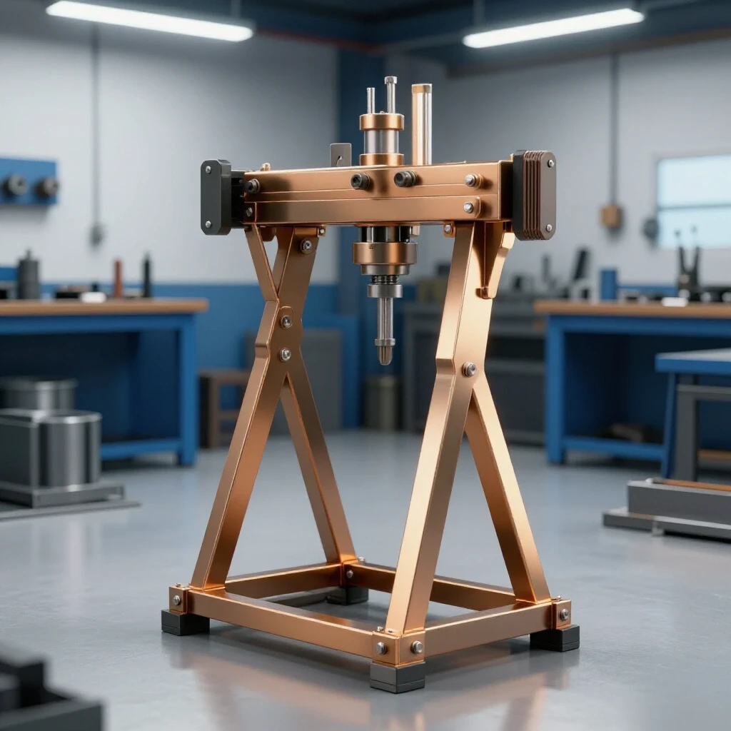
A manual rotation fixture is a workshop jig designed to hold a workpiece securely while allowing it to spin along a horizontal or vertical axis. This tool typically consists of a stable base, a vertical support column, and a rotating head with a faceplate. By using gravity and simple mechanical locks, it helps fabricators access hard-to-reach joints without straining or repositioning the entire assembly.
Before I strike an arc, I spend a significant amount of time on the drawing board. For a manual rotation fixture, you need to plan for a load capacity of about 100 kg (220 lbs). This requires a sturdy base, usually made from 2-inch or 2.5-inch square tubing with a wall thickness of at least 3/16-inch. If the base is too light, the whole unit will tip when you mount an offset load. I always sketch out my cut list first, accounting for every junction.
When planning your workshop jigs and fixtures, consider the height of your workbench. I prefer my rotation axis to sit at about 40 inches from the floor. This allows me to sit on a stool or stand comfortably while working. I also plan for a telescoping upright. This gives me the flexibility to raise or lower the project depending on its size. In my experience, a lack of adjustability is the first thing a builder regrets once the project is finished.
- Base dimensions: 30 inches x 30 inches for stability.
- Upright height: 36 inches to 48 inches (adjustable).
- Faceplate size: 8-inch to 10-inch diameter, 3/8-inch thick steel.
- Rotation axis: 1.5-inch solid round bar or heavy-wall pipe.
Calculating Kerf and Material Allowances for Accurate Square Cuts
Kerf is the width of the material that is turned into dust or chips during the cutting process. Whether you use a chop saw, a band saw, or a plasma cutter, the blade takes up physical space. If you do not account for this 1/16-inch to 1/8-inch gap, your final assembly will be shorter than intended, leading to gaps that cause structural weakness and increased warping.
To achieve accurate square cuts, I always mark my material and then align the blade so it “leaves the line.” This means the kerf is taken from the scrap side of the metal, not the part I am keeping. For a manual rotation fixture, the fitment of the telescoping tubes is critical. If your cuts are not perfectly square, the inner tube will bind against the outer tube, making height adjustments a nightmare.
I use a dry-cut saw with a carbide-tipped blade for most of my custom fabrication projects. It produces less heat than an abrasive saw and leaves a cleaner edge. If you are using an abrasive saw, remember that the blade can flex, especially on thicker material. This flex can create a slight bevel on your cut, which ruins your square alignment. Always deburr your edges with a flap disc after cutting. A small burr can throw off a measurement by 1/32-inch, which compounds across the entire build.
Metal Kerf Allowances by Cutter Type
| Cutting Tool | Typical Kerf Width | Best Use Case |
|---|---|---|
| Band Saw | 0.035″ – 0.045″ | Precision cuts, thick solid bar |
| Dry-Cut Saw (Carbide) | 0.080″ – 0.100″ | Clean, cool cuts on tubing |
| Abrasive Chop Saw | 0.125″ – 0.150″ | Roughing out large stock |
| Plasma Cutter | 0.040″ – 0.060″ | Plate steel and custom shapes |
| Oxy-Fuel Torch | 0.150″ – 0.250″ | Heavy demolition or thick plate |
Constructing the Main Support Column and Base
The main support column is the backbone of your rotation fixture. It must transfer the weight of the workpiece down to the base without flexing. For a manual stand, I use a “T” or “H” shaped base design. This provides a wide footprint while still allowing my feet to get close to the work. I avoid “X” patterns because they tend to be trip hazards in a small garage.
When assembling the base, I use a large framing square and heavy C-clamps. I never trust the factory edge of the steel to be perfectly square. I clamp the parts to a flat welding table and check the diagonals. If the diagonals are within 1/16-inch, I know the base is true. This is the first step in providing metal warping solutions; if the foundation is crooked, every weld after will pull the project further out of alignment.
I start by tacking the corners. A tack weld should be small but strong—usually about 1/4-inch long. I place tacks on opposite sides of the joint to balance the pull. If I only tack one side, the heat will pull the upright toward the weld as it cools. After tacking, I re-verify the squareness. If it moved, I can easily snap a tack with a cold chisel and reset it. Only after the entire base is tacked and checked do I begin the final weld sequencing layout.
- Layout the base members on a flat surface.
- Clamp the center upright support to the base cross-member.
- Check for vertical plumb using a level or square.
- Apply four small tacks (North, South, East, West).
- Measure the distance from the top of the upright to the corners of the base to ensure it is centered.
Designing the Pivot Assembly and Bearing Housing
The pivot assembly is the mechanism that allows the faceplate to rotate. In a manual shop fixture, this is often a simple “pipe-over-pipe” or “shaft-in-sleeve” design. While ball bearings are great, they can be sensitive to welding ground current. If you weld through a ball bearing, the electricity can arc across the internal balls, creating “pitting” that ruins the smooth rotation.
I prefer using a heavy-wall DOM (Drawn Over Mandrel) steel tube as a sleeve and a solid cold-rolled steel shaft for the pivot. This combination provides a tight fit with very little wobble. To prevent the “arcing” issue, I always attach my welding ground clamp directly to the faceplate or the workpiece, never to the base of the stand. This ensures the current doesn’t have to travel through the pivot point.
To keep the rotation smooth, I drill and tap the outer sleeve for a grease fitting (zerk). A little bit of high-temp grease goes a long way. For the locking mechanism, I weld a nut over a hole in the sleeve and use a T-handle bolt. This allows me to create friction or lock the rotation entirely. Interestingly, the weight of the workpiece often provides enough friction to keep the stand from spinning wildly, but a positive lock is necessary for safety when working on unbalanced loads.
Why Weld Shrinkage Warps Square Structures
Metal layout tips often focus on the “before,” but understanding the “after” is where the pros excel. When you heat steel to its melting point, it expands. As it cools and solidifies, it shrinks. This shrinkage exerts thousands of pounds of force on your joints. If you have a T-joint, the weld will pull the vertical piece toward the bead. This is called angular distortion.
In my years building utility trailers, I saw many builders try to fight this by clamping everything down as hard as possible. While clamps help, they cannot stop the molecular contraction of the metal. If you clamp a part too tightly and weld it, the stress stays trapped in the metal. The moment you release the clamps, the part “springs” into a warped shape. The goal is not to stop the movement entirely, but to use weld sequencing to pull the metal back into the correct position.
To manage this, I use a “backstepping” technique or a staggered sequence. Instead of running one long bead from left to right, I weld a short section, move to the opposite side of the project, and weld there. This distributes the heat evenly. For the rotation fixture’s faceplate, I weld the shaft to the plate using a star pattern, similar to how you tighten lug nuts on a car wheel. This keeps the faceplate from “cupping” or becoming concave.
Weld Sequencing and Distortion Control
| Sequence Type | Method | Effect on Distortion |
|---|---|---|
| Continuous Bead | One long pass from start to finish | High distortion; pulls heavily toward the end of the weld |
| Backstepping | Welding in short sections against the direction of travel | Moderate distortion; helps keep the joint flatter |
| Staggered/Skip | Jumping from one side of the joint to the other | Low distortion; balances the heat input across the part |
| Balanced | Simultaneous welding on opposite sides (requires two people) | Lowest distortion; forces cancel each other out |
Implementing Height Adjustability and Secure Locking Points
A height-adjustable fabrication mount uses telescoping sections of tubing to raise or lower the work. For this to work smoothly, you need a gap of about 1/16-inch to 1/8-inch between the inner and outer tubes. If the fit is too tight, any bit of weld spatter or rust will lock the tubes together forever. If it is too loose, the stand will wobble, making it hard to perform precision work.
I use a hitch-pin style locking system for the height adjustment. I drill a series of 1/2-inch holes through both the inner and outer tubes at 2-inch intervals. Using a standard trailer hitch pin is a fast and secure way to lock the height. To remove the “slop” or wobble, I weld two nuts onto the outer tube—one on the front and one on the side. I then use bolts to tighten against the inner tube, which “wedges” it into the corner of the outer tube for a rock-solid feel.
When drilling these holes, alignment is everything. I highly recommend using a drill press. If you try to hand-drill through both sides of a square tube, the bit will almost always wander, and your pin won’t go through straight. I drill the outer tube first, then slide the inner tube inside, clamp it, and use the outer holes as a guide to mark the inner tube. This ensures the holes line up perfectly every time.
Tack Welding Strategies for Structural Integrity
A tack weld is a temporary structural point that holds components in alignment before the final welding passes. In custom fabrication projects, the size and placement of these tacks determine the success of the build. If a tack is too small, it will crack under the stress of the metal shrinking. If it is too large, it becomes a bump in your final bead that looks unprofessional and can trap slag.
For the 3/16-inch and 1/4-inch steel used in this project, my tacks are usually about 3/16-inch in diameter. I place them every 3 to 4 inches along a long joint. On square tubing, I always place tacks on the corners first. The corners are the strongest part of the tube and are less likely to pull or blow through.
Before I move from tacks to final beads, I perform a “sanity check.” I use a digital protractor to check the angle of the pivot head and a string line to ensure the base hasn’t bowed. If anything is off by more than 1/16-inch, I fix it now. It is much easier to grind out a tack than it is to cut through a full-strength weld.
- Tack size: 1.5 to 2 times the thickness of the thinnest material.
- Spacing: 2-4 inches for structural frames.
- Sequence: Always tack in a cross-pattern to balance tension.
- Inspection: Hit each tack with a hammer; if it cracks, your penetration was too shallow.
Final Alignment Procedures and Post-Weld Corrections
Once the stand is fully welded, you may notice some slight movement. Even with the best sequencing, the cumulative heat can cause a few degrees of tilt. This is where post-weld correction comes in. If the upright is leaning slightly to the left, I can sometimes “pull” it back by running a “dry” bead (a bead with no filler metal or a very small one) on the opposite side. The heat from this bead will cause the metal to shrink and pull the upright back toward center.
Another technique I use is mechanical straightening. For smaller deviations, a heavy sledgehammer and a solid anvil surface can move things back into place. However, you must be careful not to dent the tubing. I often use a “cheater pipe” over the upright to apply leverage and slowly bend the base back into square.
Finally, I check the rotation of the head. It should spin freely without any high spots. If there is a bind, it is usually caused by a small piece of weld spatter inside the sleeve or a slight warp in the pivot shaft. I use a long-handled wire brush or a flap wheel on an extension to clean the inside of the sleeve. A smooth rotation is what makes this workshop jig a joy to use.
Actionable Framework for Your Build
To keep your project on track and avoid the common pitfalls of inaccurate layouts, follow this checklist during your construction process.
- Material Prep: Cut all pieces according to your list, adding 1/8-inch for each kerf if you are measuring “end-to-end.”
- Deburr: Use a flap disc to remove all burrs and mill scale from the weld zones. Clean steel welds better and warps less.
- Base Assembly: Clamp the base on a flat surface. Check diagonals. Tack corners.
- Upright Integration: Square the upright to the base in two planes (X and Y). Tack and re-check.
- Pivot Fabrication: Ensure the shaft and sleeve have a 0.010-inch to 0.020-inch clearance for grease.
- Faceplate Alignment: Tack the faceplate to the shaft while it is sitting in the sleeve to ensure it spins true to the axis.
- Final Welding: Use the staggered sequence. Never weld more than 3 inches in one spot without letting it cool or moving to the opposite side.
- Finishing: Grind any sharp edges, grease the pivot, and apply a coat of industrial enamel to prevent rust.
Conclusion
Building a manual rotation fixture is a rite of passage for many fabricators. It teaches you how to respect the heat and how to plan for the physical realities of steel construction. By focusing on accurate square cuts, understanding kerf, and mastering weld sequencing, you can build a tool that will improve the quality of every project that follows.
Remember, the goal isn’t just to finish the stand; it’s to finish it square and functional. Don’t rush the layout phase. The time you spend with your square and your scribe will save you hours of grinding and “fixing” later. Once you have a reliable way to rotate your work, you’ll find that your welds are cleaner, your penetration is more consistent, and your projects stay much closer to the dimensions you intended.
Frequently Asked Questions
Why does my metal always warp even when I use heavy clamps?
Clamps provide physical restraint, but they cannot stop the internal molecular contraction of the steel as it cools. When the weld metal shrinks, it creates internal stress. If the heat is not balanced through proper sequencing, the metal will either warp while clamped or “spring” out of shape once the clamps are removed.
How do I calculate the exact kerf for my saw?
Take a scrap piece of metal and measure it exactly with calipers. Make a single cut through the piece. Measure both resulting pieces. Subtract the total length of the two pieces from the original measurement. The difference is your kerf. For most chop saws, this is roughly 1/8-inch (0.125″).
Can I use a standard pipe for the rotation axis?
You can use Schedule 40 or Schedule 80 pipe, but be aware that standard pipe is measured by its nominal inside diameter and often has an internal weld seam. This seam can cause the pivot to bind. DOM (Drawn Over Mandrel) tubing is preferred because it is perfectly round and has no internal seam.
How many tack welds are necessary for a 2-inch square tube joint?
I recommend four tacks—one on each flat side of the tube. Place the tacks about 1/4-inch from the corners. This provides enough strength to hold the part during handling but remains small enough to be incorporated into the final weld bead.
What is the best way to ensure my upright is perfectly vertical?
Do not rely on a spirit level unless your floor is perfectly flat. Instead, use a large machinist’s square or a framing square against the base you just built. Check the upright from two directions (90 degrees apart) to ensure it isn’t leaning forward or to the side.
Why should I avoid welding through ball bearings?
The high amperage of a welder will find the path of least resistance. If the ground is on the base and you are welding on the faceplate, the current travels through the bearing balls. This causes “micro-arcing,” which creates tiny craters in the metal, leading to a “crunchy” rotation and eventual bearing failure.
What is the “backstepping” weld technique?
Backstepping involves starting a weld bead a few inches ahead of your previous stop and welding backward toward the finished bead. This helps manage heat by ensuring the start of each segment is on cooler material, which reduces the overall pull on the joint.
How do I stop the telescoping tubes from wobbling?
The best method is to weld two nuts onto the outer tube at a 90-degree angle to each other. By tightening bolts through these nuts against the inner tube, you force the inner tube into the opposite corner of the outer tube, eliminating all play.
What thickness should the faceplate be for a DIY stand?
For a stand rated at 100 kg, a 3/8-inch thick plate is ideal. It is thick enough to resist warping from the welding heat and provides enough “meat” for you to drill and tap holes for mounting various workpieces.
How do I fix a project that has already warped?
You can use “flame straightening,” which involves heating a small triangular area on the side opposite the warp. As the heated spot cools, it shrinks and pulls the metal back. Alternatively, you can use mechanical force with a hydraulic jack or a large press, though this requires caution to avoid kinking the metal.
(This article was written by one of our staff writers, Robert Kline. Visit our Meet the Team page to learn more about the author and their expertise.)