Writing Clear Custom Metalwork Project Contracts (DIY Plan)
Scaling a fabrication business from a side hustle to a professional operation is a high-stakes evolution. After twenty years in the shop, I have learned that the most stressful moments do not come from the fabrication itself, but from the gap between what is promised and what the shop can physically deliver. When you transition to high-output work, your project documentation becomes the bridge between your workshop’s physical capacity and the client’s expectations.
A clear project build plan is not just a piece of paper; it is a technical roadmap. It defines the material grades, the dimensional tolerances your CNC can hit, and the realistic timelines your current workflow allows. If your shop layout is a bottleneck or your power supply is unstable, you cannot reliably fulfill your project agreements. I have seen many talented fabricators fail because they treated their workshop as a static space rather than a dynamic system. To scale effectively, you must align your floor layout, electrical infrastructure, and automation tools with the technical specifications you provide to your customers.

Defining Project Scopes Through Material Flow Mapping
A material flow map is a visual representation of how raw metal moves through your shop, from the delivery truck to the final finishing station. Understanding this path is the first step in setting realistic project timelines and labor costs in any build agreement.
When I first integrated a CNC plasma table, I realized my old layout was costing me hours of labor every week. I was moving 4×8 sheets of 10-gauge steel across the shop three times before they even touched the water table. This inefficiency makes it impossible to provide accurate cost estimates. A professional shop layout should follow a linear or U-shaped pattern to minimize “travel waste.”
- Entry Zone: Raw material storage near the main door.
- Processing Zone: CNC plasma, bandsaws, and shearing.
- Fabrication Zone: Welding tables and jigging stations.
- Finishing Zone: Grinding, painting, or powder coating.
- Outbound Zone: Final inspection and crating.
| Layout Type | Material Travel Distance | Efficiency Rating | Best For |
|---|---|---|---|
| Random/Hobby | High (50+ feet) | Low | Single-piece repairs |
| Functional (Zoned) | Moderate (20-30 feet) | Medium | Small batch production |
| Linear/Cellular | Low (5-10 feet) | High | High-volume fabrication |
By reducing the distance a part travels, you reduce the risk of material damage and decrease the labor hours required for each build. This data allows you to document fabrication sequences more accurately in your project plans.
Why Back-and-Forth Foot Traffic Kills Shop Throughput
Foot traffic refers to the unnecessary movement of a fabricator between tools, which often results from poor tool placement or shared workspaces. Eliminating these “bottlenecks” ensures that the timelines you promise in your project documentation are consistently met.
In my early years, I kept my grinders on the opposite wall from my welding table. I calculated that I was walking nearly two miles a week just to swap tools. In a micro-manufacturing environment, every minute spent walking is a minute not spent welding. To fix this, I implemented “point-of-use” storage. Every welding station now has its own dedicated grinders, clamps, and consumables.
When you are defining project deliverables, you must account for these “hidden” labor costs. If your shop is not optimized, you will either undercharge and lose money or overcharge and lose the bid. A well-organized shop allows for a “standardized work” approach, which is a core pillar of lean manufacturing.
Establishing Electrical Reliability in Project Deliverables
Electrical reliability is the shop’s ability to provide consistent, clean power to all machinery without tripping breakers or damaging sensitive CNC electronics. This is the foundation of maintaining the quality standards promised in a custom metalwork build.
Most home-based shops start with a 200-amp single-phase service. However, professional-grade equipment like large compressors, CNC spindles, and heavy-duty MIG welders often require 3-phase power. 3-phase power provides three alternating currents that are out of phase with each other, resulting in more consistent torque and higher efficiency for motors. If your power supply fluctuates, your CNC cuts will be jagged, and your weld penetration will be inconsistent.
Choosing 3-Phase Converters for High-Output Tooling
A 3-phase converter is a device that transforms single-phase residential power into 3-phase industrial power. For advanced shop owners, choosing between a Rotary Phase Converter (RPC) and a Variable Frequency Drive (VFD) is a critical decision that impacts project quality.
- Rotary Phase Converters (RPC): These use a generator motor to produce the third leg of power. They are excellent for running multiple machines simultaneously, such as a mill, a lathe, and a compressor. They are rugged but can be noisy and consume power even when the machines are idling.
- Variable Frequency Drives (VFD): These are electronic devices that convert power and allow for speed control of the motor. They are perfect for dedicated machines like a drill press or a lathe but are generally sized for one motor at a time.
- Digital Phase Converters: These are the gold standard for CNC machinery. They provide perfectly balanced voltage (within 1%), which protects sensitive control boards and ensures the dimensional tolerances defined in your project specs are achieved.
| Power Option | Voltage Balance | Equipment Protection | Scalability |
|---|---|---|---|
| Static Converter | Poor | Low | Low |
| Rotary (RPC) | Fair | Moderate | High |
| Digital Converter | Excellent | High | Moderate |
| Utility 3-Phase | Perfect | High | Unlimited |
Managing Air Quality to Meet Fabrication Standards
Air quality management involves the use of high-volume filtration and source-capture systems to remove metal dust and fumes from the workshop. Clean air is not just a safety issue; it prevents dust from settling on precision machinery and ruining high-end finishes.
When you are writing a project plan for a client, you often promise a specific finish quality, such as a “mirror polish” or a “clean powder coat.” If your shop is filled with grinding dust from a previous stage of the project, achieving that finish is impossible. Metal dust is also conductive. If it settles on your CNC control board, it can cause a short circuit, leading to expensive downtime and missed deadlines.
Designing Dust Collection Networks for Heavy Grinding
A dust collection network is a system of ducts and a central vacuum (cyclone) designed to pull air at a specific velocity to keep particles suspended until they reach the filter. For metalwork, you need an air velocity of at least 4,000 feet per minute (FPM) in the ducts to prevent heavy steel dust from settling and creating a fire hazard.
To design an effective system, you must calculate the Static Pressure (SP) loss. Static pressure is the resistance the air faces as it moves through the ducts, elbows, and filters. If your ducting has too many bends, the airflow (measured in Cubic Feet per Minute, or CFM) will drop significantly.
- Identify the tool with the highest CFM requirement (usually a large belt grinder or CNC plasma table).
- Map the shortest possible duct path to the collector.
- Use smooth-walled metal ducting; avoid flexible ribbed hoses which increase resistance.
- Ensure the collector uses a HEPA-grade filter to capture fine sub-micron particles.
Integrating CNC Automation for Precise Dimensional Tolerances
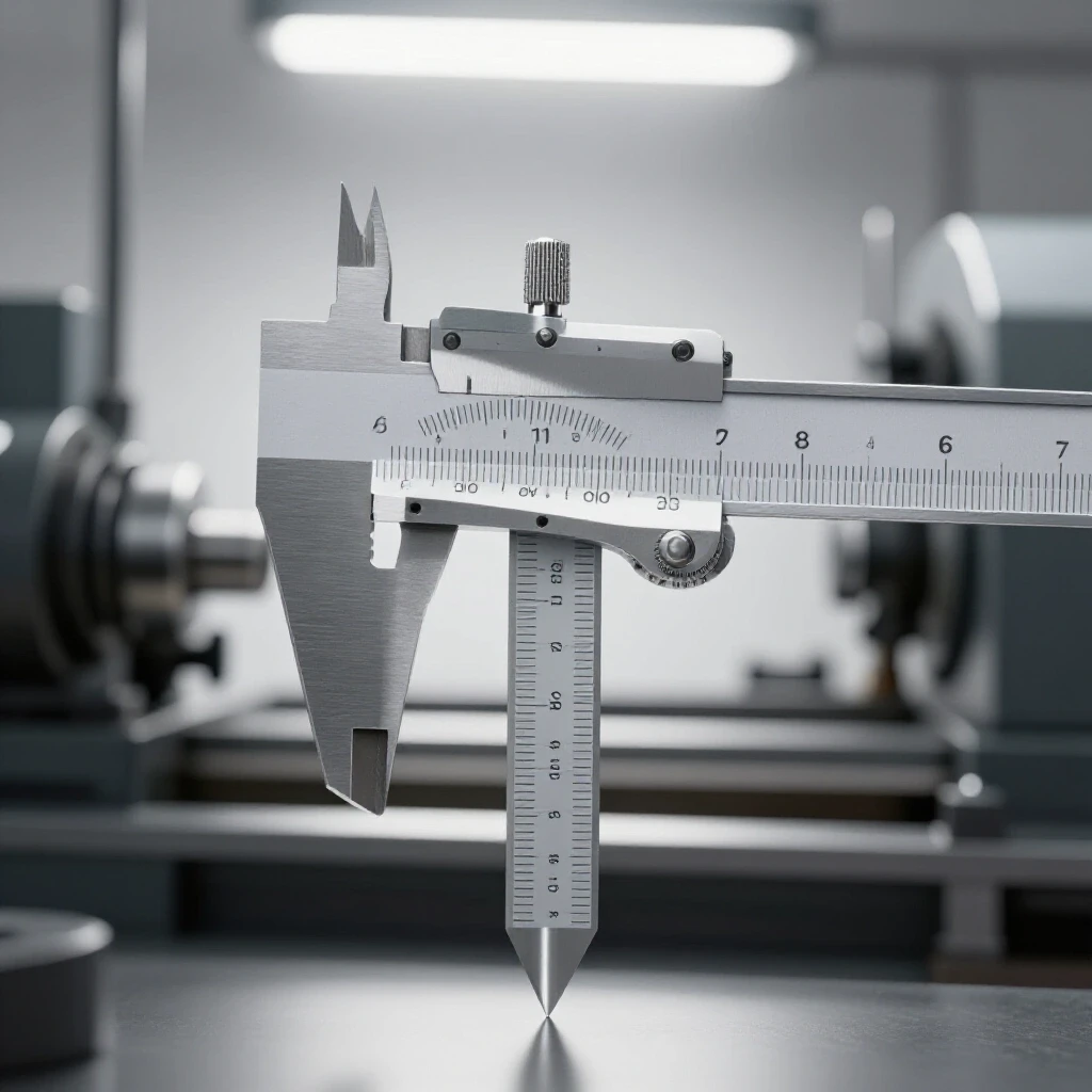
CNC integration is the process of using computer-controlled machinery to automate cutting and forming tasks. This technology allows a shop to guarantee dimensional tolerances—often within +/- 0.005 inches—which must be clearly stated in the technical project specifications.
Transitioning to a CNC plasma table was the biggest turning point in my shop’s history. However, it came with a steep learning curve. I had to learn the difference between stepper motors and servo motors. Stepper motors move in fixed increments and are more affordable, but they can “lose steps” if they hit an obstacle, ruining the part. Servo motors use closed-loop feedback, meaning they constantly communicate their position to the controller. This ensures that the machine never loses its place, providing the reliability needed for complex, high-value project builds.
Software Workflows and CAD/CAM Integration
The software workflow is the sequence of digital steps required to turn a concept into a physical part, involving Computer-Aided Design (CAD) and Computer-Aided Manufacturing (CAM). This digital trail is essential for documenting project deliverables and ensuring repeatable quality.
- CAD (The Drawing): This is where you define the geometry of the part. For custom metalwork, precision in the CAD stage prevents material waste.
- CAM (The Strategy): This software converts the drawing into “G-code,” which tells the CNC machine where to move, how fast to cut, and when to turn the torch on.
- Post-Processor: This is a small piece of code that translates the G-code into the specific “language” your machine controller understands.
A common mistake is failing to verify the “kerf” width in the CAM software. The kerf is the amount of material removed by the plasma arc. If you don’t account for this, your final parts will be smaller than the dimensions specified in your project agreement.
Practical Benchmarks for Shop Optimization
To maintain a professional operation, you should track specific metrics that reflect your shop’s health and capability. These benchmarks help you refine your project build plans over time.
- Machine Spacing: Maintain a 3-foot minimum access zone around all stationary equipment for maintenance and safety.
- Electrical Phase Balance: Use a multimeter to ensure voltage between phases is within 2-5% of each other.
- Filter Maintenance: Inspect dust collection filters every 50 hours of grinding time; replace when the pressure gauge shows a significant drop in CFM.
- Amortization Timeline: Calculate how many project hours are required to pay off a new CNC table. For a $15,000 system, if it saves 10 hours of labor per week at $75/hour, the “break-even” point is 20 weeks.
Frequently Asked Questions
How do I determine the right CFM for my dust collector? Most metalworking tools require between 800 and 1,200 CFM at the source. However, you must account for static pressure loss in your ducting. A 2HP cyclone collector is usually the minimum for a professional-grade micro-shop.
What is the difference between closed-loop and open-loop CNC systems? Open-loop systems (steppers) send a signal to move but don’t check if the movement happened. Closed-loop systems (servos) use encoders to verify the position, ensuring the machine stays accurate even under heavy loads.
Can I run a CNC plasma table on a rotary phase converter? It is possible, but not recommended. CNC electronics are sensitive to voltage imbalances. A digital phase converter or a dedicated single-phase plasma power supply is a much safer bet for protecting your investment.
How does shop layout affect my project pricing? Poor layout increases “non-value-added” time (walking, searching for tools, moving material). If your layout is optimized, your labor cost per part drops, allowing you to be more competitive in your project bids.
Why is duct air velocity important for metal dust? Metal dust is heavy. If the air velocity drops below 4,000 FPM, the dust will settle in the bottom of your horizontal duct runs. This creates a fire hazard and can eventually lead to a complete blockage of the system.
What should I include in the technical specifications of a project agreement? Always include material grade (e.g., 6061 aluminum vs. 7075), dimensional tolerances (e.g., +/- 1/16″), finish requirements, and a clear fabrication sequence. This protects you from “scope creep.”
How do I balance the load on a 3-phase converter? You should try to distribute your single-phase loads (lights, small tools) across the two “real” legs of the converter, leaving the “manufactured” third leg primarily for the 3-phase motors.
What is the most common mistake when scaling a fabrication shop? The most common mistake is buying a large CNC machine without upgrading the electrical and air filtration systems first. Without the proper infrastructure, the machine becomes a bottleneck rather than a solution.
How often should I recalibrate my CNC table? I recommend a weekly “squaring” check and a monthly deep-clean of the rails and lead screws. This ensures the dimensional accuracy you promise in your project documentation remains consistent.
What are the signs of an electrical bottleneck in the shop? Signs include flickering lights when a welder strikes an arc, CNC controllers rebooting unexpectedly, or motors running hot. These issues indicate that your shop’s current draw is exceeding its capacity.
Scaling a workshop is a journey of constant refinement. By focusing on the physical systems that govern your shop—layout, power, air, and automation—you create a foundation that allows your project documentation to be accurate and reliable. This systematic approach is what separates a hobbyist from a professional fabricator. When your shop is optimized, you can take on more complex builds with the confidence that you will deliver exactly what you promised.
(This article was written by one of our staff writers, Edward Sinclair. Visit our Meet the Team page to learn more about the author and their expertise.)